The Little Known CCD
CCD means “Controlled Current Distribution” and refers to distribution of RF current on a resonant antenna. Ordinary antennas (lets use a half-wave dipole as an example) show a current distribution like this.
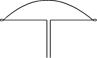
Whereas a CCD shows a current distribution something like this:
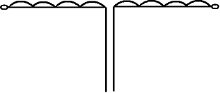
Notice that the current at every point along the length of the CCD antenna appears to be evenly distributed, hence the name.
Ground Immune!
Advantages of a CCD antenna compared with an ordinary wire antenna are many and important. For an example there is NO standing wave voltage on the antenna which means that the “end effects” are negligible. The CCD is relatively immune to ground and other objects because of this feature, and may be laid out on the ground and still operate effectively! This means also the CCD can be placed close to walls, tree branches, other antennas and objects, with very little interaction.
Height and Signal Advantages
The CCD appears to put out a better signal than an ordinary antenna at the same height, and seems to have a lower angle of radiation for a given height above ground. Keeping these advantages in mind, you should know that there are some disadvantages of a CCD—mostly mechanical. It is a bit tedious to construct, it is twice as long as a conventional wire antenna, and it is a bit more expensive, too, because of the capacitors that must be placed every few feet from feedpoint to end.
Excite Your Contacts
If you can put up with these minor inconveniences and enjoy trying something new and different, then the CCD may be for you. Oh yes, one other thing: your contacts on the air will be longer and more frequent because the stations you work will want to know all the details of this little-known antenna. In fact, the author has sent out more than 25 packages of information to other hams who have shown a great interest in constructing a CCD antenna.
Stations worked by the author include other CCD antenna enthusiasts like John Caldow, W4DJS of Tuscaloosa, Alabama; Mel Craine, W7YOF, of Payson, Arizona; Gary Rennie, KC8BN/7 of Mesa Arizona, and Glen Rothwell, W7BL near Seattle, Washington. These stations put out uniformly good signals-among the better ones on the band(s).
Multi-band
The CCD is useful on all bands above and including its lowest or “design” frequency. The 40 meter version described here has been used successfully on 40, 30, 20, 17, 15, 12, and 10 meters. In most cases a tuner is necessary for every band except the lowest band , where it has a natural resonance and may be fed directly with a simple 300 or 450 balanced line. In the author’s case, a 6:1 or 4:1 balun has been used with 50 ohm and 75 ohm coax respectively. The feedpoint may be virtually anywhere along the antenna inasmuch as the currents are uniform; i.e., “constant”. The feed point impedance is on the order of about 250 ohms, and the antenna can be “bent” in many shapes without harm.
More Reports to Come
As the author gains more experience with his CCD, he continues to gain more experience for its designers: W4FD and W4ATE, who hold the patent on this unique antenna. Signal reports are uniformly better than with the other antennas available at the home station—under ALL conditions; interference (RFI) to other nearby electrical and electronic devices is minimized (perhaps because of the lack of that high voltage loop present on ordinary antennas).
Good for Close Environment
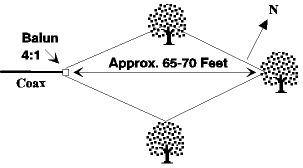
Because I was unable to afford the 140-odd feet to stretch out my own 40-meter CD in s straight line, I “bent” it around into a diamond shape only 65 or 70 feet from point to point and about 25 feet from side to side! Consider this possibility for a small lot: placing two CCDs side by side, supported by common supports, and phased for increased gain. Awesome!

Of course you will want to know where more information about the CCD can be found, so look at the references accompanying this article and obtain copies from 73 Magazine, WGE Center, Hancock New Hampshire 03449. It is possible that these issues may be out of stock because, after all 18 years IS a long time to store old magazines. If they can’t help then maybe you can find the right issues in a private collection somewhere—even in a used book and magazine supply store, and, of course, your library.
The two “landmark” articles by W4FD and W4ATE appeared in the October 1978 and July 1981 issues of 73 (See Below). The others listed in the references are if interest, and worth obtaining if you can find them, but these two are almost essential.
Constructing the 40-Meter CCD
The accompanying sketches show how mine was constructed, but other methods are possible. The capacitors should be 5% tolerance and silver mica are recommended although polystyrene caps can be used. The voltage rating doesn’t need to be very high, and a working dc voltage of 200 volts is plenty, even for an amateur kilowatt. Some builders like to parallel each capacitor with 47k-ohm resistor as a static charge protection device where the resistors “bleed” off charge and prevent its accumulation.
A Quiet Antenna
The CCD is a “quiet” antenna compared to what you may have been using, and I think that is because of the lack of a high-voltage loop on the antenna. I would advise protection of the capacitors and insulators by means of either wrapping with shrink tubing as I did, or “potting” them with a waterproof silicone-based caulking compound such as bathtub sealer.
The small capacitor leads are fragile, and must be protected from stress caused by relative movement between each wire end and the capacitor itself. the “potting” or shrink-wrapping seems to do the job adequately.
References
Antenna Design: Something New W4FD, W4ATE, October 1978;
The CCD Antenna—Another Look, W4FFD, W4ATE, July 1981;
The CCD Antenna Revisited W4ANL, May 1982, and KC8BN had an article in 1983 in 73 date and title unknown to author;
This Antenna Is Too Good To Be True W4HDX February 1984; all of the articles mentioned were in 73 Magazine.
The last article The High-Performance Capacitively Loaded Dipole May 1984 HAM Radio magazine.
CCD antenna design parameters
7.0 MHz Antenna lowest end design frequency:
Overall length – 140.571 feet
48 wire sections. #18 wire
Each wire section: 35.1428 inches long
Wire Xl : 58.2306 ohms
Capacitor Xc :58.206 ohms
Cancellation nearly perfect.
46 capacitors of 390 pF ( perfect cancellation is 390.454 ohms)
Use 6′ of ½” PVC tubing each 1½” in length
Drill holes ¼” from each end.
Fill with RTV caulk after antenna is finished.
10.1 MHz Antenna lowest design frequency:
Overall length: 97.4257 feet (Alternate: 97.18 feet)
62 wire sections, #16 wire, each 18.857 inches (Alternate: 64 sections, each 18.81″)
60 Capacitors @ 390 pF (Alternate: 62 Capacitors 390 pF)
Full cancellation requires 395.233 pF (Alternate: Complete cancellation requires 394 pF)
Cancellation not complete, but close
18.06 MHz Antenna lowest design frequency:
Overall length 54.46 feet
52 wire sections #16 wire, each 12.5679″ long
50 capacitors of 201 pF
Complete cancellation requires 197.787 pF
Impedance bridge measurements on my 40-M CCD arranged in a horizontal diamond configuration with near end sloping to 7 feet above ground.
| Frequency (MHz) | Resistance (Ohms) | Reactance (Ohms) |
|---|---|---|
| 0.7000 | 035 | 100 (L) |
| 10.100 | 025 | 025 (L) |
| 10.125 | 020 | 025 (L) |
| 14.060 | 026 | 150+ (L) |
| 18.070 | 100 | 050 (L) |
| 18.145 | 100 | 050 (C) |
| 21.045 | 175 | 160+ (L) |
| 21.200 | 175 | 060 (L) |
| 24.900 | 090 | 060 (C) |
| 24.980 | 100 | 060 (C) |
| 28.000 | 030 | 140 (C) |
| 28.500 | 030 | 140 (C) |
6:1 balun at feed point 7 feet RG-59/U
MFJ Impedance bridge & TS-930 Receiver
04.150
214
025 (L)
Tentative comparison between the 135 foot diamond loop (open end) and the 141 foot CCD diamond at the same height and position. Both fed with 450 ohm “ladder line” and a 4:1 balun and 75 ohm coax (7′ RG-59).
| Band | Average Signal Plain Loop | Average Signal CCD Loop | With Loop |
|---|---|---|---|
| 10 | S-4 | ID | ID |
| 12 | ID | S-5.5 | ID |
| 15 | ID | ID | S-7 |
| 17 | S-6.75 | S-7.5 | S-8.4 |
| 20 | S-6 | S-5.6 | ID |
| 30 | S-7.5 | S-8.25 | S-6.5 |
| 40 | S-7.5 | S-8.5 | ID |
ID = Insufficient Data
- The only bands for which sufficient comparison data is available were 40, 30 and 18 meters, which happens to be the bands I work mostly, and also – coincidentally perhaps – the bands on which the CCD has a “natural resonance”.
- On 20 meters there appears to be no significant difference between any of the loops.
- On 18 MHz the CCD was almost one S unit better than the plain loop and was almost 2 S units better with the sloping CCD loop.
- ON 30 meters the CCD loop was about one S unit better than the plain loop, but the sloping CCD did not appear as good. However, the reason may be that when the recent tests on 30 m were made with the sloping CCD, the bands were in very bad shape.
- ON 40 meters the CCD has a clear 1 S unit advantage over the plain diamond, but not enough data exists to compare the sloping CCD.
Related Downloads
