Antenna Impedance Fundamentals
Antenna Fundamentals
To get a good understanding of the fundamentals of antennas, read the following then study the drawings, and read it again. I could find no other way to present the information and have it make sense.
We know that current passed through a resistance will cause heat. In other words) the power that caused the current is dissipated in the form of heat. We also know that current passed through the radiation resistance of an antenna will be converted to a radiated magnetic field. if you pass current through a reactance, the current is shifted in phase, but no power is dissipated (converted to another form such as heat or radiated energy.) If the current passes through a reactance, there is no dissipation.

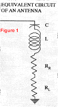
We all understand what a resistor is, and now we will gain an understanding of a reactance. The equivalent circuit of an antenna (Figure 1) is comprised of an inductor (coil), a capacitor, radiation resistance, and loss resistance.
The resistance of an antenna has a value, expressed in Ohms of resistance. We can calculate the amount of current flowing through a resistor using Ohm’s law, which states that E=I*R, where E is the voltage in Volts, I is the current in Amps, and R is the resistance in Ohms. We can rearrange the equation to give I=E/ R. This simply says that for a given voltage across the resistor, the current is related to the resistance. For example, if the resistance doubles, the current will be decreased by a factor of 2.
Next, we will find a way to calculate the equivalent equation for reactance. The word resistance is simply a resistance to current flow. In the same manner reactance is simply reactance to current flow. For this reason, the value of reactance is expressed in Ohms.
A resistor has the unique property that it has the same value at all frequencies. However, the amount of reactance (to current flow) that an inductor or capacitor has is a function of frequency. The inductance of an antenna has a value expressed in Henrys. The capacitance of an antenna has a value expressed in Farads. For an inductance, the reactance XL is defined as:
1
XL2*pi*F*L
Where:
XL is the reactance in ohms
pi has a value of 3.14159
F is the frequency in Hz (cycles per second)
L is the value of the inductance in Henrys.
This says that if the frequency (F) of the voltage increases, the value of reactance of an inductor increases. If we substitute XL for R in Ohm’s law we get:
2
l=E/XL=E/(2*pi*F*L)
This says for a given amount of inductance in the antenna, the amount of current flow decreases as the frequency increases. In other words, if F increases, the reactance increases, which in turn causes the current (1) to decrease.
3
The reactance of a capacitor (XC) is defined as: XC=1/(2*pi*F*C)
Where:
XCis the reactance in Ohms
pi=3.14159
F is frequency in Hz
C is the value of the capacitor in Farads.
If we put this into Ohm’s law we get:
4
l=E/XC=E/(1(/2*pi*F*C))=E*2*pi*F*C
This says that if the frequency increases the reactance decreases, which causes the current to increase as frequency increases.
Impedance Defined
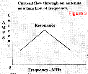
This will be easier to understand if we draw a picture (Figure 3) of current flow versus frequency for a resistor, an inductor, and a capacitor.
This assumes that a constant voltage is applied to each component independently. If we connect the components in series to form an antenna (Figure 1) and plot the sum of the radiation resistance, loss resistance, capacitor reactance, and inductor reactance, the plot in Figure 3 will be the result. When we add resistance and reactance, we call the sum-Impedance.

When you pass current through a resistor, power will be dissipated. We said that there is no power dissipated in the reactance due to current flow, therefore, relative to power dissipation, this is really an imaginary concept. The value, in Ohms, of each component is often drawn as a vector diagram as shown in Figure 4. Since resistance is real, it is drawn on the real axis (horizontal axis of the vector diagram). Inductive reactance is plotted on the imaginary axis (vertical axis of a vector diagram) as a positive value (since it increases with frequency) and capacitive reactance is plotted on the imaginary axis as a negative value (since it decreases with frequency) . Not that all three axis have a value expressed in Ohms.
Mathematical Picture
To give a mathematical notation to reactance, we place a j in front of the value. This says it lies on the imaginary axis of the vector diagram. Since inductive reactance is positive and capacitive reactance is negative, they are denoted as jXL and -jXC. Since the reactive components have opposite signs (+/-), they can be algebraically added. That just means you subtract the smaller from the larger and use the sign of the larger. Therefore the
reactance, denotes as:
5
X=jXL – jXC
At some frequency they will be equal in value, therefore X = 0. This is defined as the resonant frequency of the antenna. (Would I have led you through all of that without a reason?)
By definition, the impedance (Z) of an antenna is the sum of the resistance and the reactance, which is:
6
Z = R + jX
To show all of the components of this equation for an antenna, (see Figure 1),
7
Z=RR + RL+ jXC
This equation can only be written because all of the components of it have a value expressed in Ohms, therefore Z has a value of Ohms. To explain this equation, assume we measure the impedance of an antenna slightly above its resonant frequency. For our example, assume RR has a value of 48 Ohms, RL has a value of 2 Ohms, jXL has a value of 200 Ohms, and – jXC has a value of 100 Ohms. Therefore:
8
Z = 48 + 2 + j200 – j100
If we separately add the real and imaginary values, Z = 50 + j100. Now the question is, how do you add real and imaginary numbers?
Take a look at Figure 5. Each value from above is plotted. If we first subtract the smaller reactance from the larger, the result is +jl00 Ohms. Now we draw a line from the value of resistance (R) to the value of reactance (X). The length of that line is the value of impedance (Z) of the antenna at one particular frequency. We can calculate the value using principles of geometry since we have a right triangle. The answer is:
9
Z2 = R2 * X2
If you take the square root of Z2 you have the true value of Z. Now ain’t that simple? You have learned the concept of imaginary numbers, complex algebra, geometry, vector algebra, fundamentals of antenna theory, and all that in one easy lesson that normally takes a college degree in Engineering. If you read it twice, give yourself a degree, and if you understand it, you probably didn’t need to read it in the first place.
Now you ask, why did we do all of that? Is this trip really necessary? And the answer is yes, there is a purpose. If you look at the VSWR of your antenna as you change the transmitter frequency, it follows the curve as shown in Figure 2. There is a minimum value of impedance, corresponding to the resonant frequency of the antenna. The minimum impedance is the value of the sum of the radiation and loss resistance of the antenna, which occurs at the frequency where XL and XC are equal. At all other frequencies the impedance of the antenna is high. The high reactance reduces the amount of current flow through the radiation resistance, which reduces the radiated signal from the antenna for a given amount of transmitter power. Therefore, the antenna must always be operated at, or very near, the resonant frequency of the antenna. For convenience, the relative performance of an antenna is normally measured in terms of its VSWR. We can calculate VSWR as follows:
10
VSWR==Z/Z0
where Z0 is the transmission line impedance, normally 50 Ohms. Since the value of Z increases either side of the resonant frequency, it is the reactance of the antenna that controls the useful bandwidth of the antenna.
For our example:
11
Z = 50+ j100
We said Z2 = 502 + (j100)2. What do we do with j? Some clever fellow decided that the value of j = -1. The rules of algebra say that -1 squared = +1, also +1 squared = +1. Now you know why we call it an imaginary operator, but it serves its purpose very well.
Look at Figure 5 one more time. Notice there is an angle between the resistance and impedance. This is the angle of the current flow through the antenna for our example values.
An understanding of the impedance of an antenna will allow you to appreciate the various parameters of an antenna and their effect on the design and construction of an antenna. Future articles will build on these basic concepts, so keep this one for bedtime reading until it is as familiar as Grimm’s fairy tales.
I am sorry but I am missing the Images: Figure 2, Figure 4 and Figure 5, if anyone has these I would be very grateful for a copy.
Originally posted on the AntennaX Online Magazine by Ted Hart, W5QJR
Last Updated : 18th April 2024

