DDRR An Antenna for Small Spaces
The Direct Drive Ring Radiator antenna was originally designed for military usage. The original configuration consisted of a large diameter copper tubing supported on insulators over a ground plane. This configuration works well with large metallic objects such as ship decks.
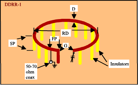
The DDRR is an antenna that has not seen much use on the amateur bands due to lack of information. The size of this antenna for any given frequency range, is considerably smaller than a normal antenna of the same frequency range. For example, an vertical antenna for the 1.8 MHz amateur band is approximately 180 feet (54.9m) tall, however the DDRR is only 36 feet (11m) across and 6 feet (1.8m) tall. An example of the DDRR is illustrated in Figure 1. All important dimensions are shown and labeled in this diagram. These dimensions are as follows:
R = diameter of the pipe
D = radius of the pipe
SB = height of the insulators
FP = feed point distance from the gap between the two ends of the antenna. This is measured from the closed end.

DDRR Dipole
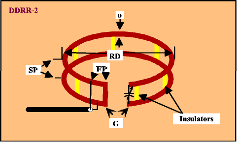
An alternate antenna for use on insulated surfaces is the DDRR dipole antenna. This antenna is visible in Figure 2 and consists of two pieces of pipe separated by insulators and connected together in one end and with the tuning capacitor at the opposite end. This enables the antenna to function normally, even though it is not over a conducting surface. The bottom half of the antenna acts as the conductive surface for the top half of the antenna. All dimensions are the same for the dipole DDRR.

Dimensions
The dimensions to build one of these antennas can be found in the Table below. A similar Table can be found in the ARRL Antenna Book and the standard and metric dimensions are extremely small for the frequencies listed .As an example, for 1.8 MHz, ring diameter is 36 feet and height is 48 inches, (10.94 meters and 121.92 CM). It can be seen that these dimensions will allow an antenna of this size to be used in a very discrete manner. This is important for people living in restricted areas where antennas are not permitted for any reason. If you decide to construct one of these antennas, you must keep in mind the voltages found on this antenna are very high and can injure anyone or any animal that may come into contact with the antenna. Precautions should be taken to avoid having anyone or an animal coming into contact with this antenna.
Quarter Wave DDRR Element Dimensions (Imperial)
| Frequency (MHz) | Feed Point | Gap | Capacitor (pF) | Spacing | Tubing Diameter | Ring Diameter |
|---|---|---|---|---|---|---|
| 1.8 | 12 in | 16 in | 150 | 48 in | 5 in | 36 ft |
| 3.5 | 6 in | 7 in | 100 | 24 in | 4 in | 18 ft |
| 7 | 6 in | 5 in | 70 | 11 in | 2 in | 9 ft |
| 10 | 3.5 in | 4 in | 50 | 7.5 in | 1.5 in | 6 ft |
| 14 | 2 in | 3 in | 35 | 6 in | 1 in | 4.5 ft |
| 18 | 1.5 in | 2.8 in | 20 | 5 in | 7/8 in | 4 ft |
| 21 | 1.5 in | 2.5 in | 15 | 4 3/4 in | 3/4 in | 3 ft 4 in |
| 24 | 1.8 in | 2.2 in | 15 | 4 in | 3/4 in | 2 ft 5 in |
| 28 | 3 in | 2 in | 15 | 3 in | 3/4 in | 2 ft 4 in |
Quarter Wave DDRR Element Dimensions (Metric)
| Frequency (MHz) | Feed Point | Gap | Capacitor (pF) | Spacing | Tubing Diameter | Ring Diameter |
|---|---|---|---|---|---|---|
| 1.8 | 30.48 cm | 40.64 cm | 150 | 121.92 cm | 12.7 cm | 10.94 m |
| 3.5 | 15.24 cm | 17.78 cm | 100 | 60.96 cm | 10.16 cm | 5.47 m |
| 7 | 15.24 cm | 12.7 cm | 70 | 27.94 cm | 5.08 cm | 2.73 m |
| 10 | 8.89 cm | 10.16 cm | 50 | 19.05 cm | 3.81 cm | 1.82 m |
| 14 | 5.08 cm | 7.62 cm | 35 | 15.24 cm | 2.54 cm | 1.36 m |
| 18 | 3.81 cm | 7.112 cm | 20 | 12.7 cm | 2.222 cm | 1.21 m |
| 21 | 3.81 cm | 6.35 cm | 15 | 12.065 cm | 1.90 cm | 101.6 cm |
| 24 | 4.57 cm | 5.588 cm | 15 | 10.16 cm | 1.90 cm | 73.66 cm |
| 28 | 7.62 cm | 5.08 cm | 15 | 7.62 cm | 1.90 cm | 71.12 cm |
Construction
Construction of this antenna is not difficult, but it must be kept in mind that extremely high current will be found on these antennas, therefore, large diameter conductors should be used, and insulation should be of high quality. The tuning capacitor should also be rated to withstand current and voltage appropriate to the power applied to the antenna. The antenna can be either fix tuned or remote motor tuned, depending on your needs.
Several versions of this antenna have been constructed-usually the people doing the building have used undesirable materials such as steel tubing and other such less conductive materials. For this type of antenna, only highly conductive materials, like copper, should be used if possible. Even small diameter copper tubing will be better than any other material for minimizing losses in this type of antenna.
Use Tubing – Not Wire!
Several of these antennas have been constructed using large diameter wire, however the losses in this type of construction are very high. A DDRR constructed of wire will receive very well, but the transmitting efficiency is very low due to losses in the small diameter wire, because of the wire’s resistance. Thus, it is far better to construct these antennas using small diameter tubing instead of wire. Any tubing is better than wire, even small diameter copper tubing. Another note to keep in mind is the smaller tubing will cause the antenna bandwidth at resonance to be less than if the antenna was built with large diameter tubing.
Tuning
The tuning procedure for this antenna is simple. Make a feed point connection several inches from the end of the closed end of the antenna. Next, set the transmitter to put out a small amount of carrier in the middle of the band you want to operate. Now tune the capacitor and watch your SWR meter. When the reflected power falls to its lowest reading, the next step is to adjust the feed point tap for the lowest VSWR. There will be interaction between the tuning and any feed point movement, so you will have to retune for minimum VSWR every time you move the tap. By following this procedure, you will be able to get the VSWR to 1:1. The VSWR should remain low over the entire band.
Originally posted on the AntennaX Online Magazine by Richard Morrow, K5CNF
Last Updated : 22nd April 2024
