High Angle of Radiation Antenna
Why would anyone want an antenna with a high angle of radiation? Well, there are many reasons for such an antenna. First thing that comes to mind is a disaster such as a hurricane, where you need to communicate over distances less than 600 miles. Secondly, you might not want to talk more than 600 miles or so to carry on with local round tables. Having an antenna that has a high angle of radiation will cut down on the QRM coming from stations out of the area that you want to talk to. This type of antenna will be very good for usage in valleys with tall hills or mountains surrounding the antenna site. Of course there are other types of high angle antennas and those will be discussed in future articles. It also gives you a much stronger signal locally than a conventional antenna. That takes care of a casual requirement, so let’s look at emergency situation first.
Before anyone starts to say the VHF and UHF systems can handle traffic like this, wait until you have seen what a hurricane does to an area, so, forget it. Hurricanes mow down towers, antennas, and everything else in its path. Thus, having a good backup HF system is essential. After hurricane Celia hit Corpus many years ago, there was very few towers up and even the ones that survived could not be reached due to the flooded fields which had lots of rattlesnakes swimming around in them.
In this case, for example, a lot of traffic needs to be in a local region within about 300 miles. A hurricane hitting here in Corpus Christi, Texas would require the traffic to and from to be strictly of an emergency nature pertaining to supplies and equipment for cleanup and aid of all types. Since the nearest major cities are San Antonio, Victoria, Houston, Austin and Waco, all of which are within 350 miles or so, and is the needed coverage. Dallas and Ft. Worth are farther out but still within the range of this type antenna.
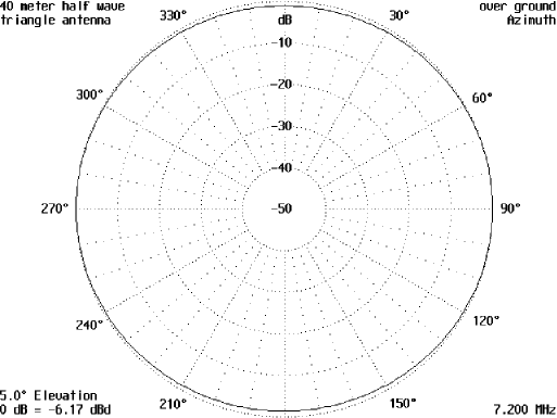
A good design is to take a 1/4 wavelength of wire and use a 16-foot pole to hold it up in the middle. Feed the antenna at one end and tie the other end down a few inches above ground. This will give an antenna that will have almost a circular pattern. Figure 1 is the horizontal pattern of this antenna and Figure 2 is the vertical pattern. As you can see, most of the energy will go nearly straight up with some directivity in the direction of the feedline. Rolling the feedline up into a RF choke should eliminate this slight directivity. This is the sort of pattern needed for this type of communications.
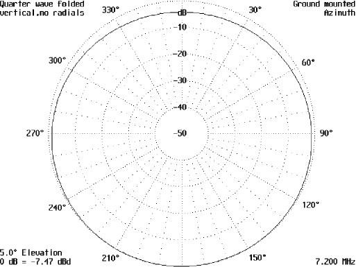
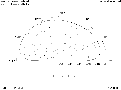
Figure 3 is the antenna configuration and also shows current distribution along the antenna. The center pole is approximately 16.25 feet tall and the ends of the antenna are 16.25 feet from the center. Construction of this antenna is not very difficult.
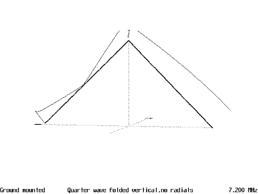
A ground rod is needed at the feed end to ground the shield of the coax and the other end needs to be tied to some sort of stake driven in the ground. One of the local sporting good stores, in this case Academy, has some telescoping fiberglass poles that are about 4 1/2 feet long when they are collapsed and 15 feet long when fully extended. This is an example of the sort of pole that you need to use. Metallic poles will not do too well as it would be 1/8 wavelength and will also radiate and the problem of insulating the antenna wire cones into play. The fiberglass will end this sort of problem. There are enough problems to go around when a hurricane or other disaster hits your area without bringing in some more. PVC pipe will do also. A simple matching network will also be needed and an L network will be adequate for this purpose.
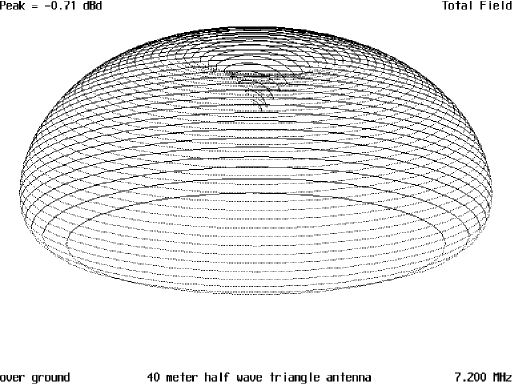
A duoband version of this antenna consists of a 1/4 wave wire cut for 75 meters. This will work on both 75 and 40 meters with pretty much the same pattern, except on 40 meters, the vertical pattern as seen in Figure 4, shows the angle of radiation has fallen to approximately 25 degrees. This is a much lower angle and will get out even further. It might make a good DX antenna. The horizontal pattern in Figure 5 is for all practical purposes, a circular one. The 3-D pattern in Figure 7-6 shows the dimple in the top of the pattern.
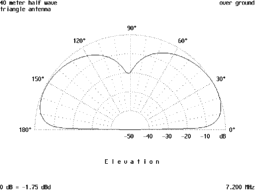
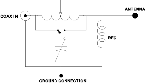
On 75 meters the patterns are identical to the 40 meter ones. In the case of the duoband antenna the center pole is approximately 32 feet tall and the ends of the antennas are spaced out a distance equal to the height of the pole. This antenna will definitely require a matching network of some kind. Again, the reversible L network will take care of matching. Figure 7 is an example of this type of network. You may use whatever values you may have on hand to build this network.
Originally posted on the AntennaX Online Magazine by Richard Morrow, K5CNF
Last Updated : 28th March 2024
