The Magnetic Hairpin Monopole for 20-40 Meters
Last month (January 2001 issue of antenneX) I started experiments with a trapped version of the Magnetic Hairpin Monopole antenna that would use a tuned circuit in place of the switched short in the hairpin antenna described in John Kuecken’s book “Antennas and Transmission Lines”. To calculate the traps I used a Smith Chart simulation program. Testing the computed circuit gave at best an SWR of about 6:1 and it appeared the radiation resistance of the antenna was too low.
Drop the Trap
This month, I extended the hairpin over that of last month’s experiment to 93 inches in total length, which is the maximum height that will fit upright between the basement floor and the ceiling at my dwelling. The trap then gave an SWR of 4:1 at best, and there was no nice best position for the trap. In fact, the inductance required, 0.22 uH, was only about 2 turns 1/2-inch in diameter. Hanging the trap halfway up the antenna proved mechanically difficult to do in an adjustable, electrically “at a single point” way. I have concluded that the trap idea is not practical.

Getting Better


At 7 MHz, the received signal was between -70 and -80 dBm and had strange behavior with frequency as one moved the twinlead around. At the tuned frequency, where the SWR was 1 to 1, the received signal sometimes had a notch in amplitude. This went away when I put a 2-can “dipole” radiator on the end of the twinlead (the “cans” were cylinders 4 inches in diameter and 6 inches long spaced about 0.5 inch end to end). But the radiation never got above -70 dBm.
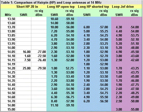
Table 1a also shows data at 14 MHz for a 93-inch twinlead hairpin with the same dimensions as the 93-inch hairpin in Table 1. It shows that the twinlead hairpin has a maximum radiated signal of -61.75 dBm versus -52.75 for the copper pipe version. This demonstrates the effect of the lower losses in the pipe version.
I think a wire version of the hairpin, which might be very unobtrusive, would work better made out of ladder line and hung fully vertical. The method of tuning the hairpin seems to be very easy and reliable in all cases.
Table 2 shows how the hairpin versions behave at 7 MHz (the short hairpin wouldn’t tune to 7 MHz and I didn’t record the twinlead version data). At 7 MHz, the 93-inch hairpin exhibits a radiation between that of the other two antennas at 14 MHz (-63 and -67 dBm for open and shorted top respectively). The Qs and bandwidths are almost the same, as shown in Table 5, and reflect the different radiation characteristics. Both radiate 10 times better than the short hairpin does at 14 MHz.


The champion of all the antennas in this experiment at 14 MHz, however, is the loop. It radiates 10 dB better than the long hairpin while having a higher Q (=42) and it operates over a 330 kHz bandwidth! It uses about half the 1 inch copper pipe, compared to the long hairpin, so it probably has half the resistive losses and obviously more radiation loss. Table 1 shows the loop performance on the same scale as the hairpins. Photo 1 shows the octagon loop antenna used in this experiment. The boss “snowflake” decided he wanted to be the size scale instead of the meter stick behind him. He is 36 inches from nose to tail tip. Photo 2 shows the Jef drive tuner. Photo 3 shows the boss inspecting the work.


Conclusion
Both the Loop and the Hairpin are magnetic antennas, each with a different form factor. The hairpin is a squashed loop! Table 3 compares the areas of these loops, and shows that the hairpin antenna has an enclosed area about 8 dB less than the loop, which is a hexagon of 1-inch copper pipe about 30 inches in diameter (Its area is that of a 30-inch square minus the area of the 4 triangles chopped off at the corners of the square). This accounts for 8 dB of the improved performance. The loop also has a pattern gain, which may explain the other 2.3 dB of the better performance. This comparison points to the importance of enclosed area in magnetic antennas. (I wonder if the CFA might work better with some configuration that maximizes the area of the D plate???)

Originally posted on the AntennaX Online Magazine by Joel C. Hungerford, KB1EGI
Last Updated : 30th May 2024

