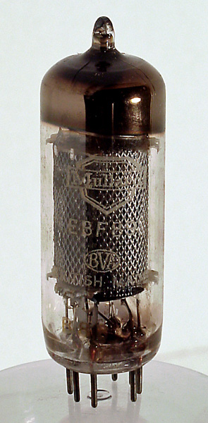
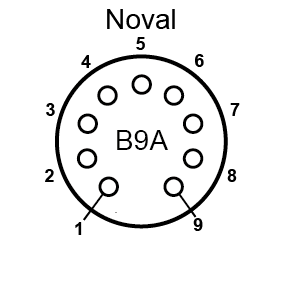
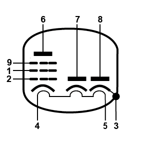
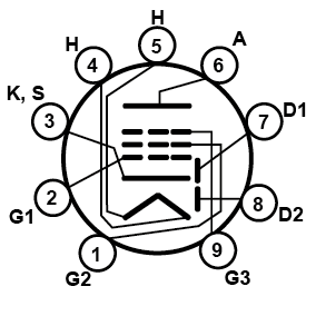
EBF89 by MD0MDI Quantity in Stock 11 Location Box E.1 The EBF89 features two signal diodes and a variable μ pentode in the one envelope and sharing a common cathode. The diode anodes are small plates placed either side of an extended cathode tube. The variable μ characteristic is indicative of a device designed to have its gain controlled by an AGC system. This places this valve in service as a final IF amplifier and detector. The high impedance of the pentode supports the case for use with a tuned circuit connected to the anode. Type EBF89 was first introduced in 1958. Pin 1: Grid Number 2 Pin 2: Grid Number 1Pin 3: Cathode, Internal Screen Pin 4: Heater Pin 5: Heater Pin 6: Anode Pin 7: Anode (D1) Pin 8: Anode (D2) Pin 9: Grid Number 3 Specifications Vf : 6.3vIf : 300mAVa : 250vVs : 100vVg : -2vmAa : 9mAmAs : 2.7mARa : 1MΩ Substitutes 6DC86FD1210FD12 (Different Filament Voltage)UBF89 (Different Filament Voltage) Datasheets EBF89 Mazda Datasheet … 483.00 KB 9 downloads EBF89 Philips Datasheet 1 … 65.44 KB 14 downloads EBF89 Philips Datasheet 2 … 209.23 KB 10 downloads EBF89 Tesla Datasheet … 1.23 MB 11 downloads Thanks to the Valve Museum for the information collected here. Share WhatsappTelegramLINESkypeEmail