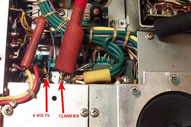
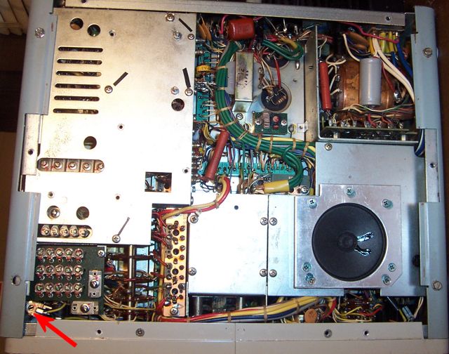
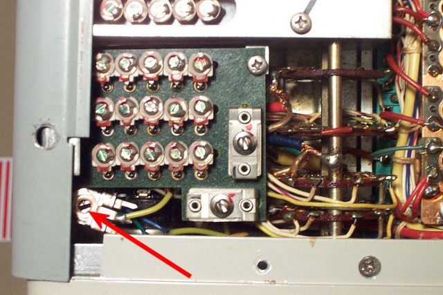
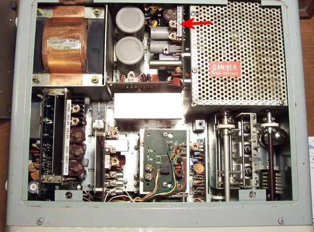
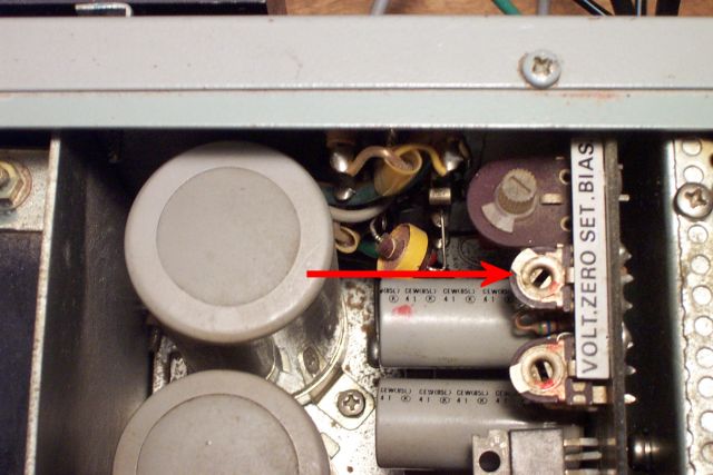
Yaesu FT-101B Clarifier and TX/RX Frequency Alignment by MD0MDI Remove top and bottom covers and attach a voltmeter to the ‘VFO Clarifier’ input. Attach a voltmeter to the 'VFO Clarifier' input. Turn radio on.Set the ‘Clarifier’ to “0”.Radio needs to be in PTT Receive mode.Take a reading of the ‘Clarifier’ Voltage.Set the ‘Clarifier’ to ‘off’.Adjust VR4 on the back of the ‘Clarifier’ so that you see the same Voltage that you read when the ‘Clarifier’ was set to “0.” Location of VR4 Pot inside the Chassis Below is a closer view of VR4. You may have to loosen up the cabinet side plate to get access to it: Close-up View of the BVR4 Pot inside the Chassis Make sure that the voltage is the same when you turn the clarifier between “0” and “Off.”Adjust again if necessary.Make sure that the heater switch is in the ‘OFF’ position.Set the radio to ‘MOX’.Now use the ‘zero” control on the top near to the rear to set the ‘Clarifier Voltage’ to the same value as you saw when the radio was in Receive mode. Location of the 'Zero Control' Pot within the Chassis. Below is a close-up of ‘Zero’ Control Pot. Close-up of the Location of the 'Zero Control' Pot You’re finished, reassemble the radio and you’re done. Facebook Twitter LinkedIn Last Updated : 31st July 2024 Share WhatsappTelegramLINESkypeEmail