I have borrowed all of the images from various websites to get this page up and running whilst my collection of Yaesu FT-101’s has been building up, I have enough to start adding my own content to this and the other pages on this website, so please bare with me as this will take quite some time.
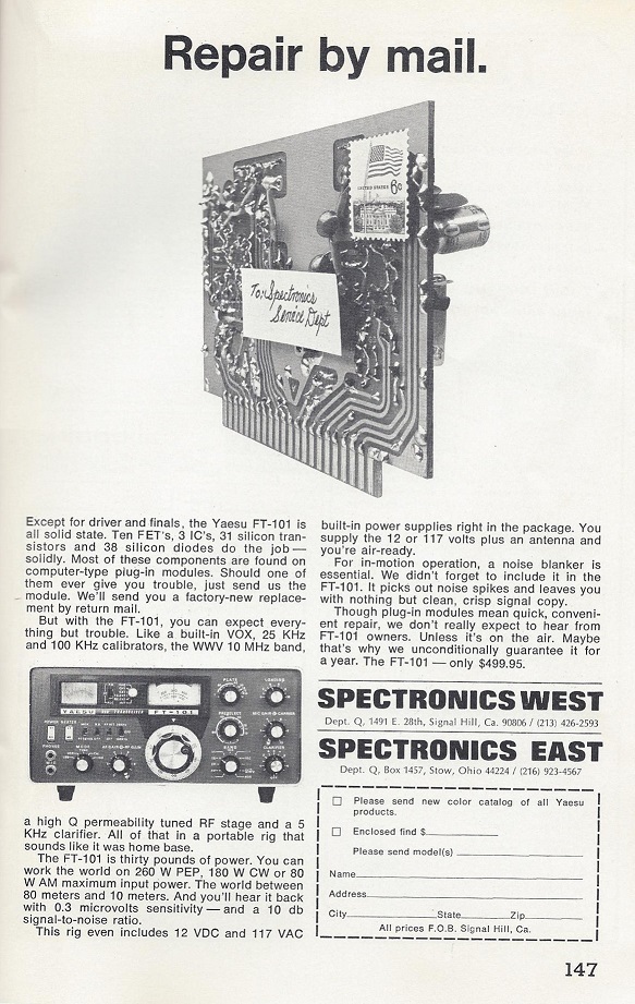
First Advert for the Yaesu FT-101 (QST Magazine 1971-01)
Internal Modules
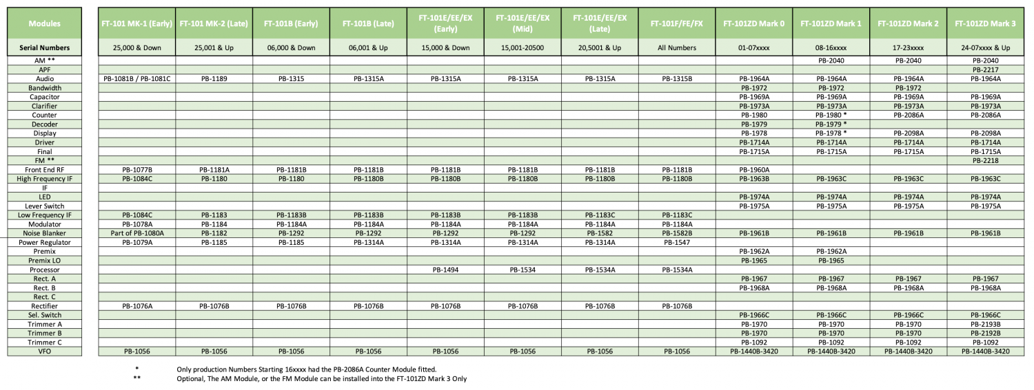
Below is a Module Matrix of all known PCB Module Numbers and the Models of the Yaesu FT-101 Transceiver that they are installed into.
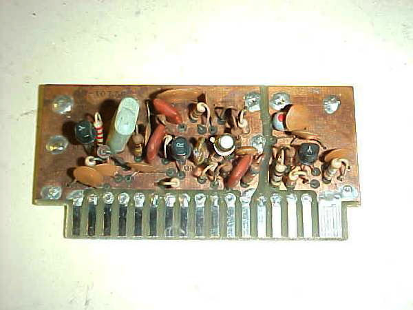
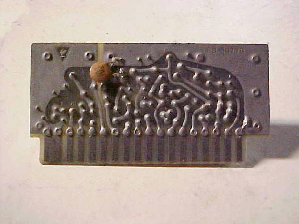
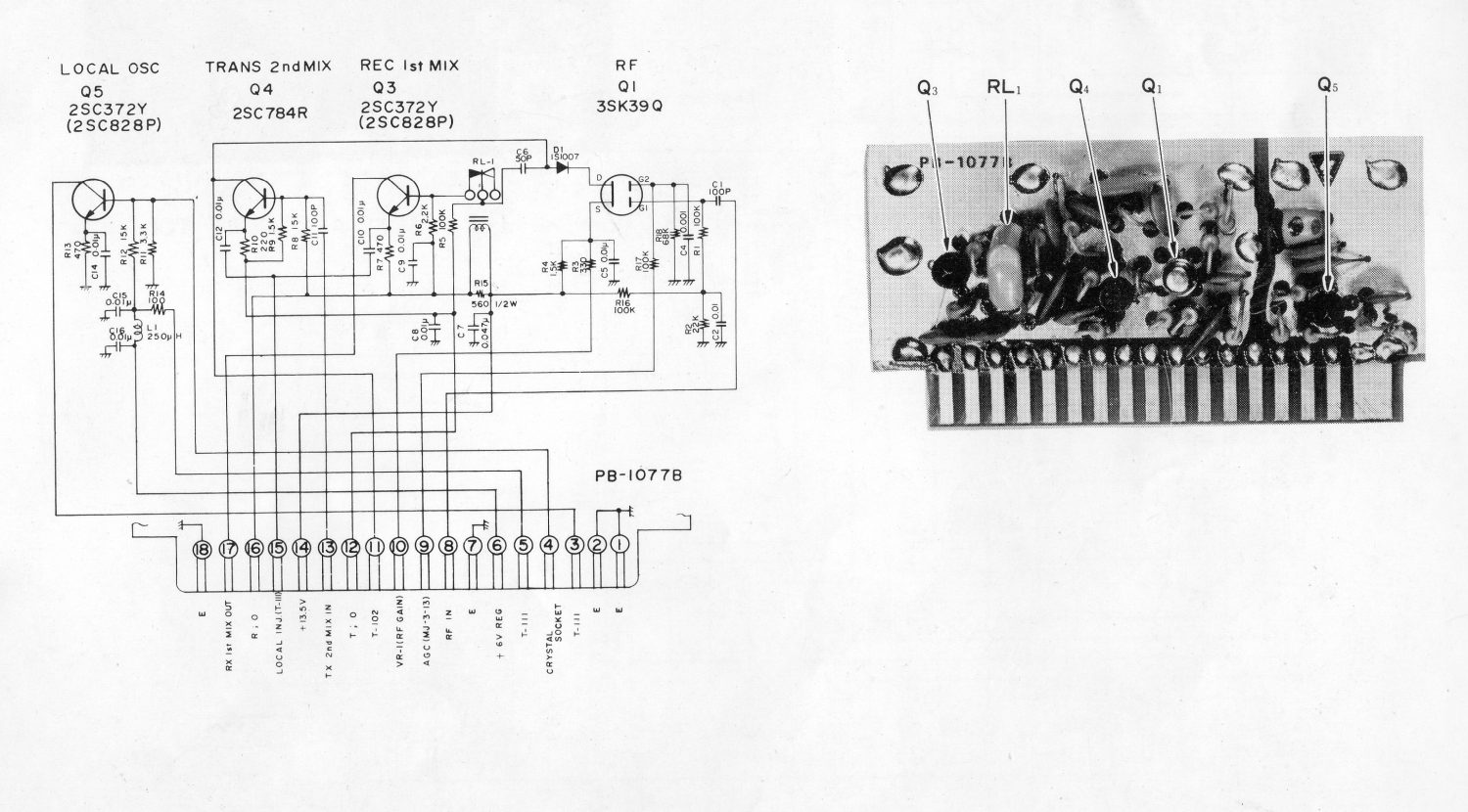
Photo of PB-1077B Front End RF Module that was fitted into the very early Yaesu FT-101 Transceivers.
The RF Module contains the receiver RF Amplifier, Receiver 1st Mixer, Transmitter 2nd Mixer and Heterodyne Oscillator circuit.
The base circuit of the Receiver Mixer Q3 on this board is disconnected in transmit by a small relay (RL1) to avoid the lowering the Q of the Receiver 1st Mixer circuit while in transmit mode.
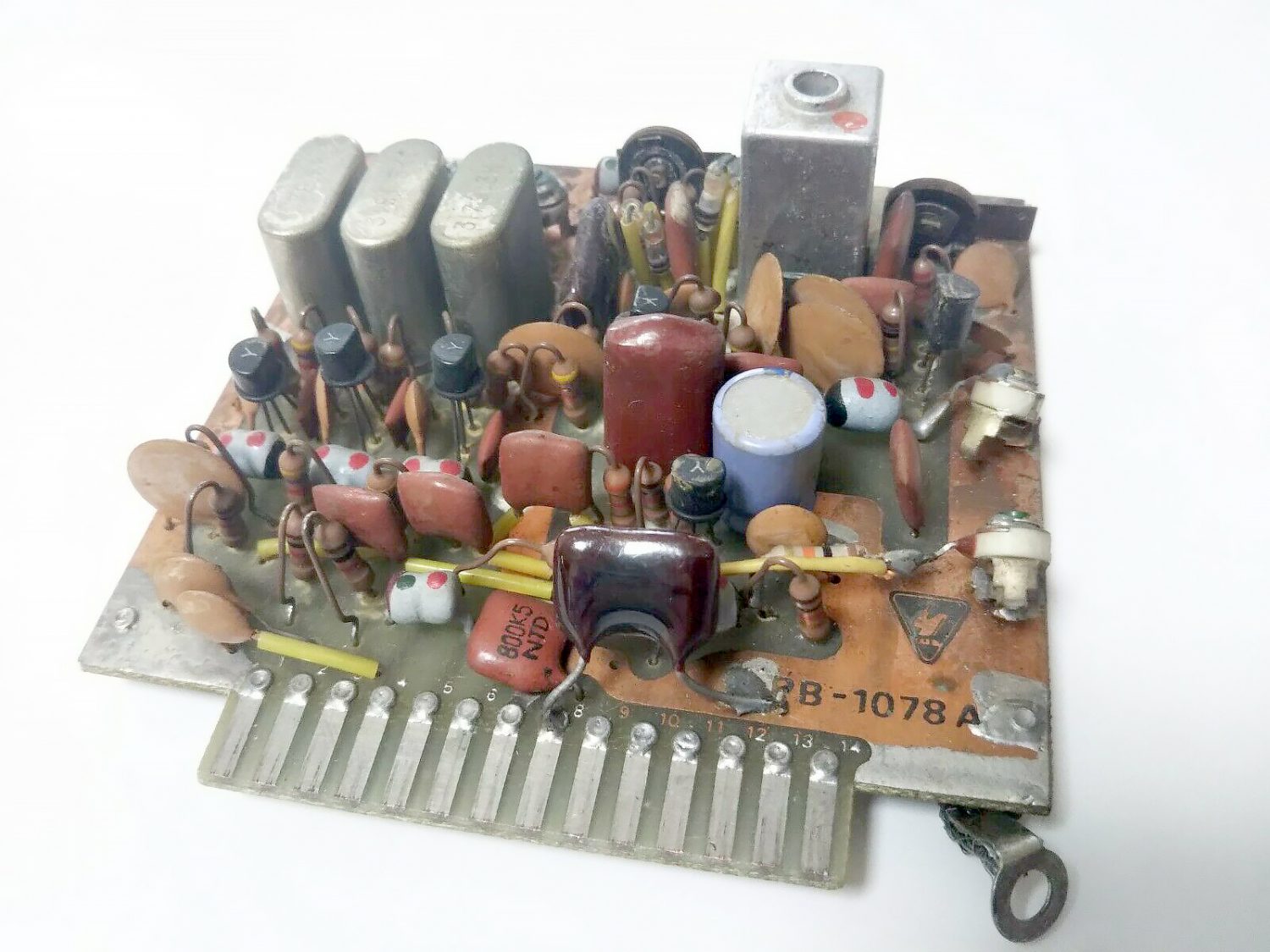
There is really very little difference between a PB-1078A and a later PB-1184A.
There should be no reason what so ever that the two can not be interchanged, if needed.
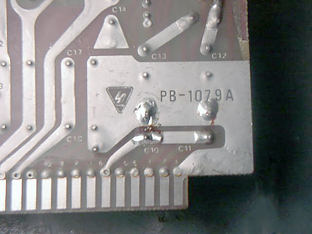
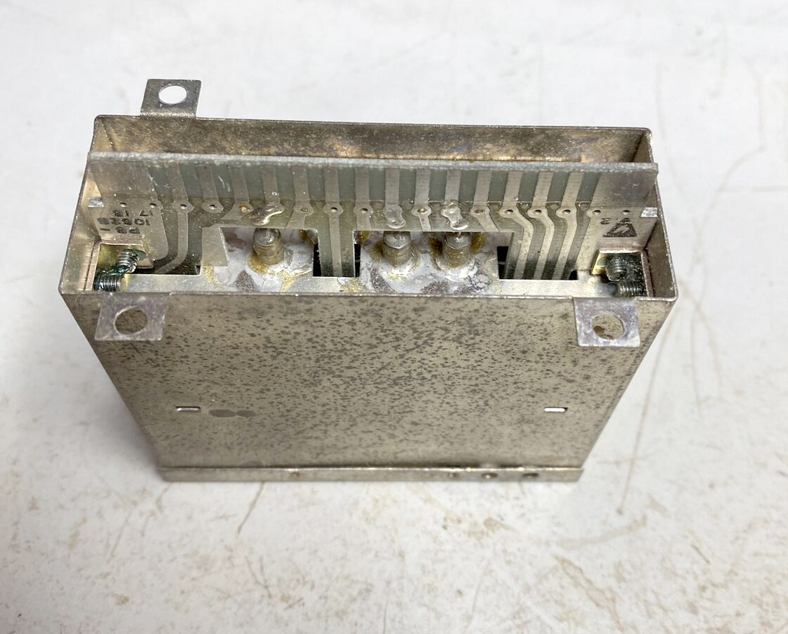
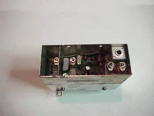
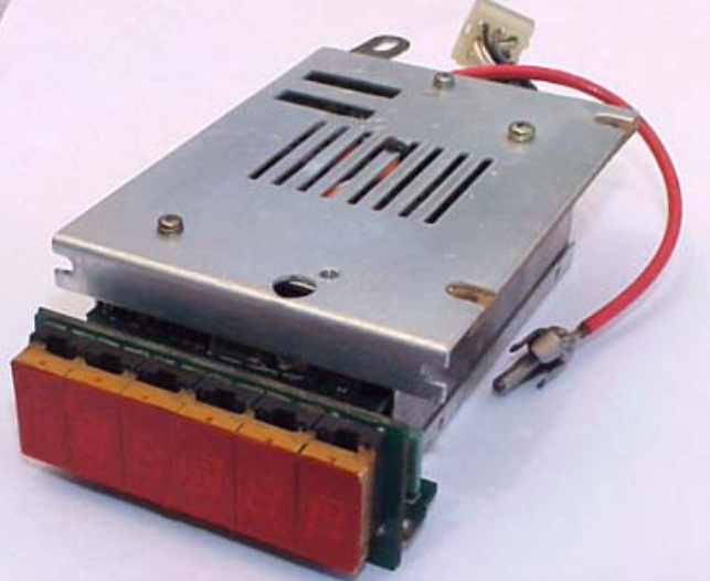
PB-1079A - Power Regulator Module
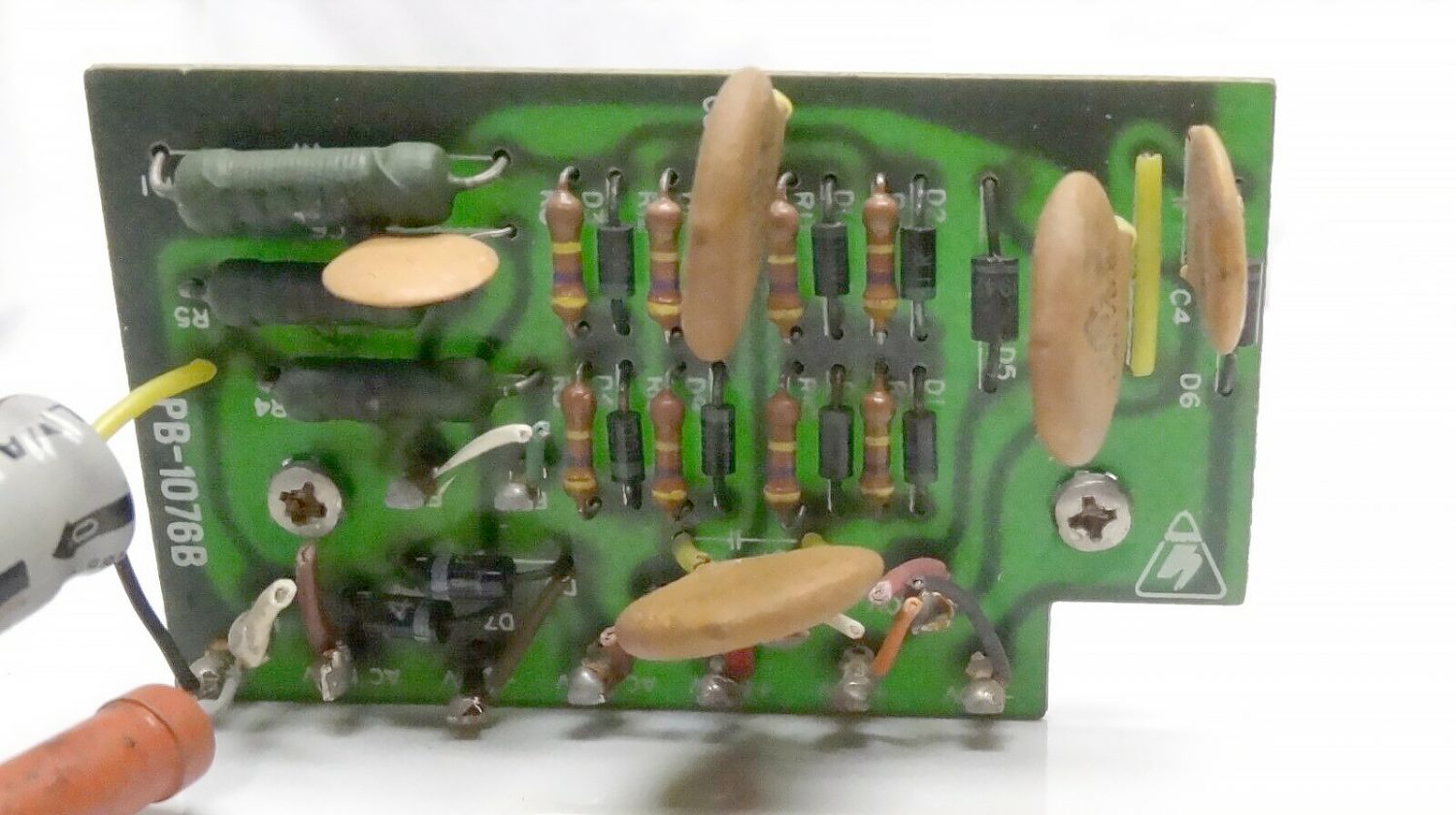
Photo of PB-1079A Power Regulator Module Fitted to the Early Yaesu FT-101 Series Transceiver
Throughout the production of the Yaesu FT-101 series of transceivers there were many changes to the ‘Power Supply Regulator’ module.
However they all basically did the same thing but the circuitry was improved.
The DC 13.6 volts from the rectifier unit is filtered on this board and produces a stable 6 volt DC supply.
Regulated voltage is provided to the clarifier and VFO circuits for stability from this board.
The regulator board also has a transmit bias control on this board.
A (-100 volts) negative one hundred volts supply sets the operating bias to the final amplifier tubes at approximately -50 volts.
The bias for the 12BY7A is also supplied from this board. (-20 volts) negative twenty volts on receive and (-3.5 volts) three and a half volts on the driver tube during transmit.
The Power Regulator Module PB-1079A in the very early transceivers used two NPN transistors to provide a stable 6 volt DC supply voltage needed for the rest of the transceiver and also produced a 100 KHz and 25 KHz marker signals.
This unit is easily identifiable by it’s large heat sink on the regulator transistor Q5 (2SC697) and the large 100 KHz HC-13U crystal used in it’s marker generator.
PB-1079B - Power Regulator Module
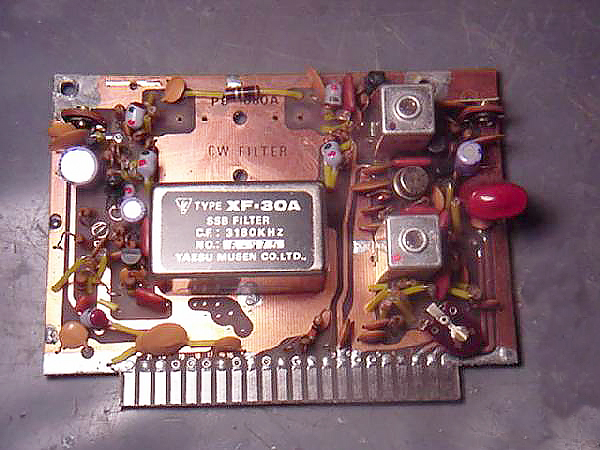
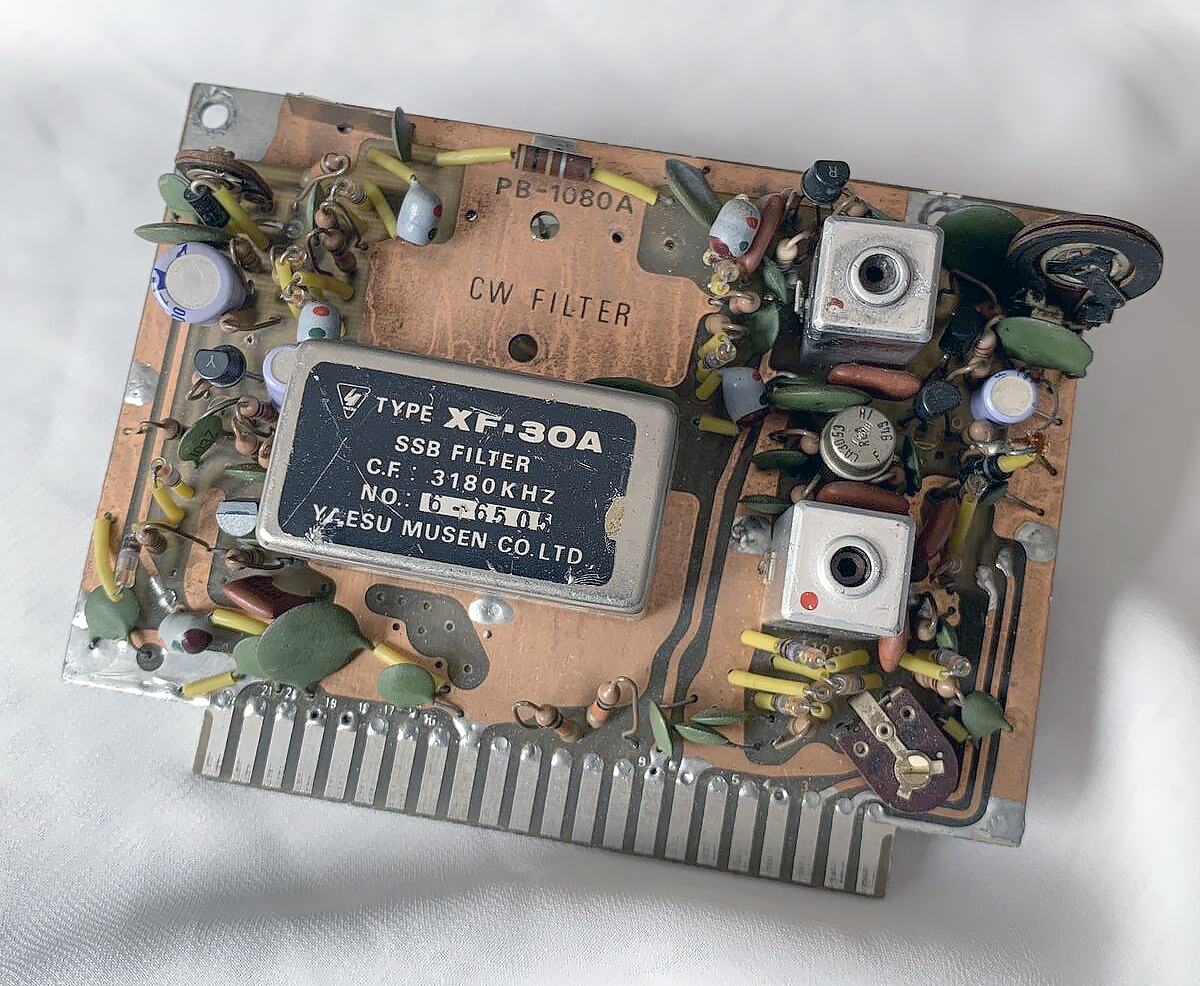
PB-1080A - Low Frequency IF Module
Photo of the PB-1080A Low Frequency IF Module fitted in the Early Yaesu FT-101 Transceiver
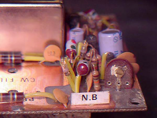
Photo of Noise Blanker section that is located on the PB-1080A Low Frequency IF Module
Please Note that you cannot replace the PB-1080A with the newer PB-1183, i.e. install a PB-1183 into an early Yaesu FT-101 which uses a PB-1080A.
The reason you can not update an early transceiver with the PB-1183 Module is that the very early Yaesu FT-101’s have the ‘Noise Blanker’ circuitry fitted on the PB-1080A.
Later models in the series, the Yaesu FT-101/B/E/F had a plug in noise blanker boards such as PB-1582B shown below.
In the case of the original late model Yaesu FT-101 there was a Noise Blanker which included the Crystal Control board (PB-1182) this unit was installed on top of the VFO and the interconnection of this module were wired directly without using plug-in socket.
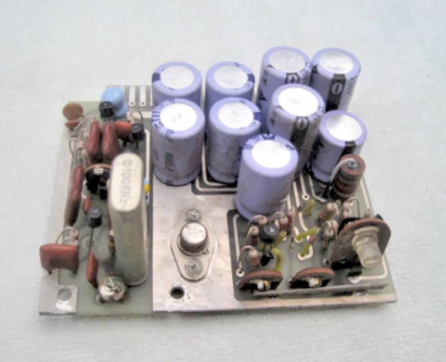
PB-1081B and PB-1081C - Audio Modules
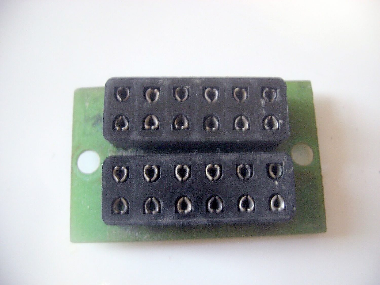
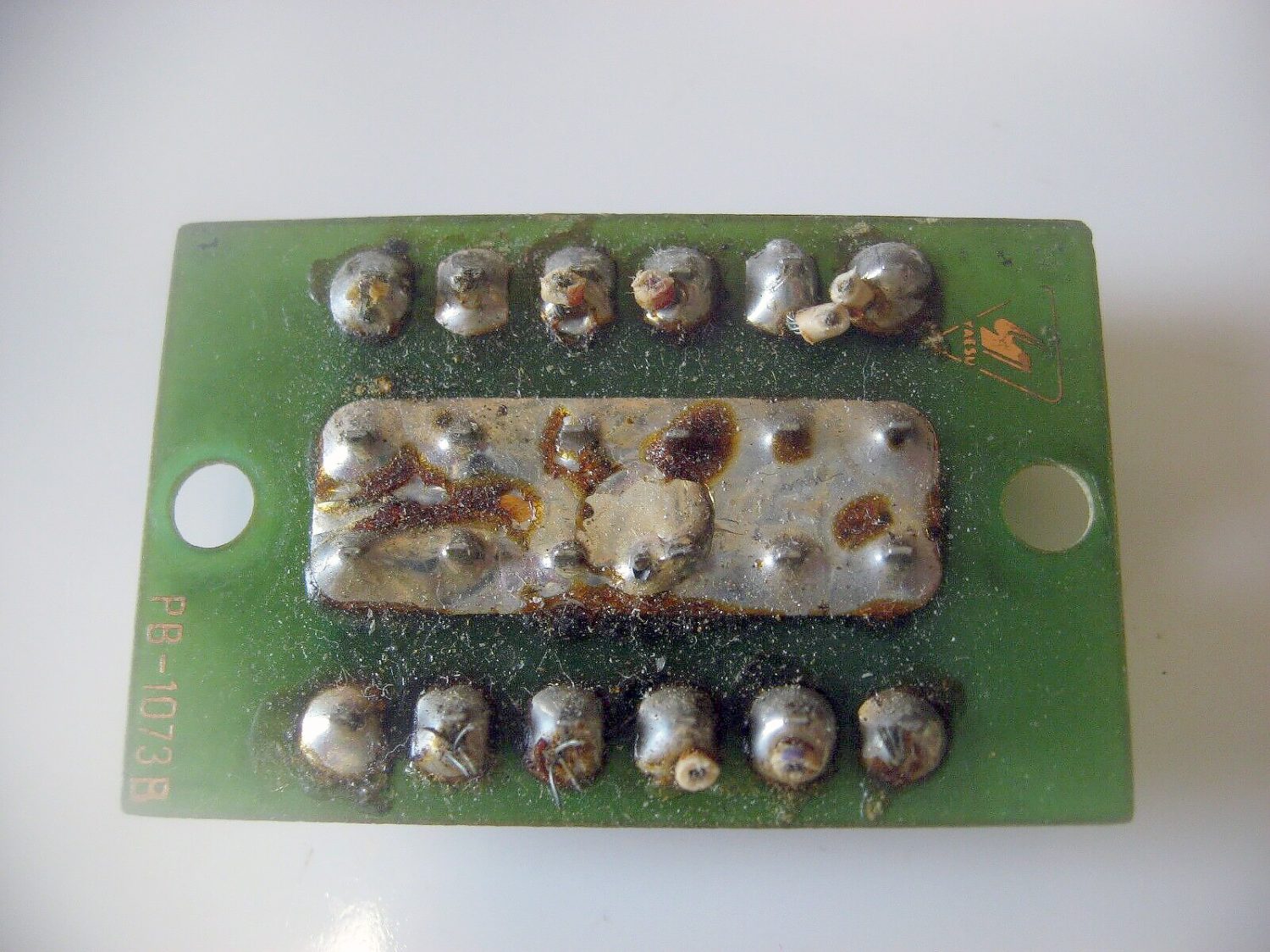
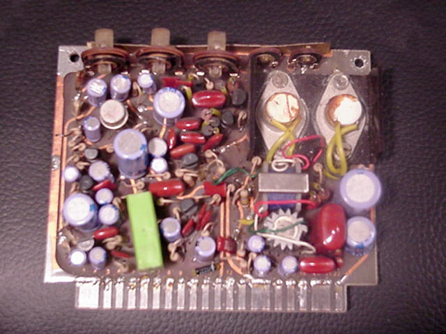
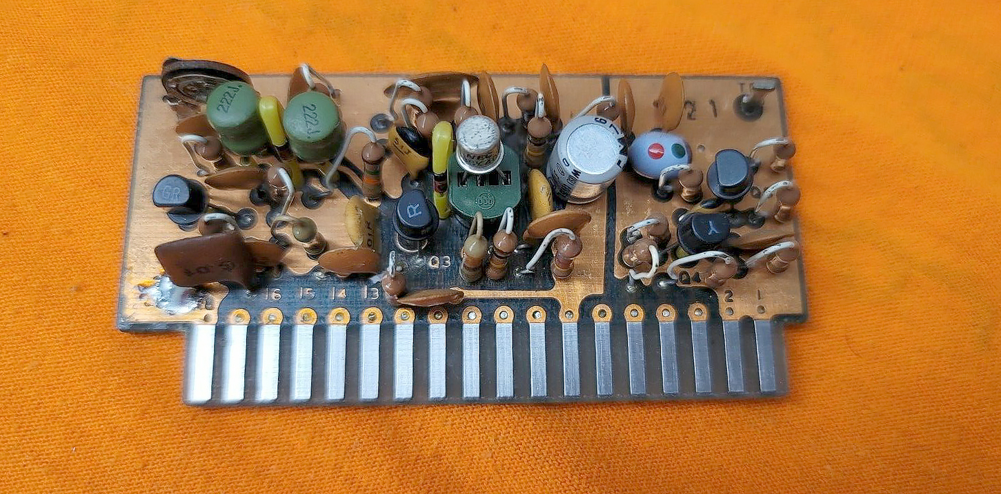
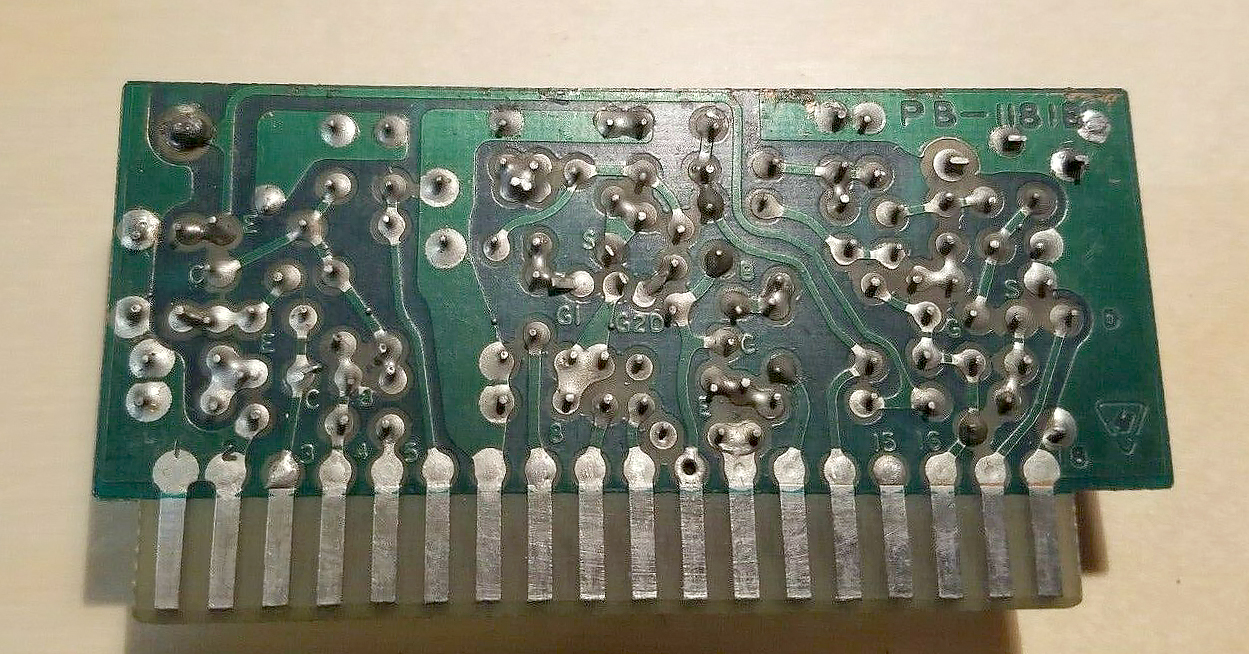
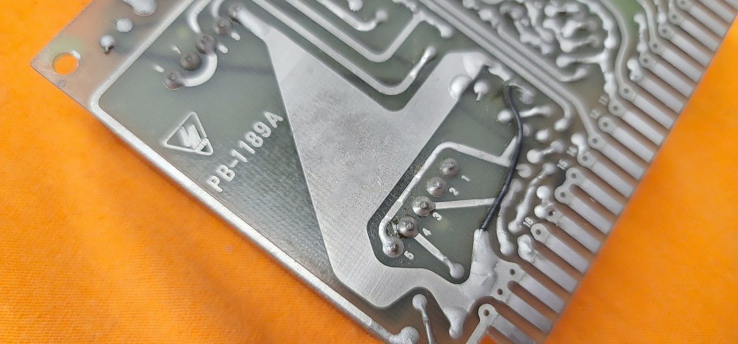
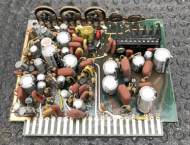
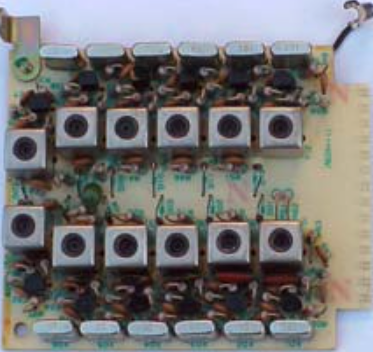
Photo of PB-1081B Audio Module that is installed in the very early Yaesu FT-101 Transceivers
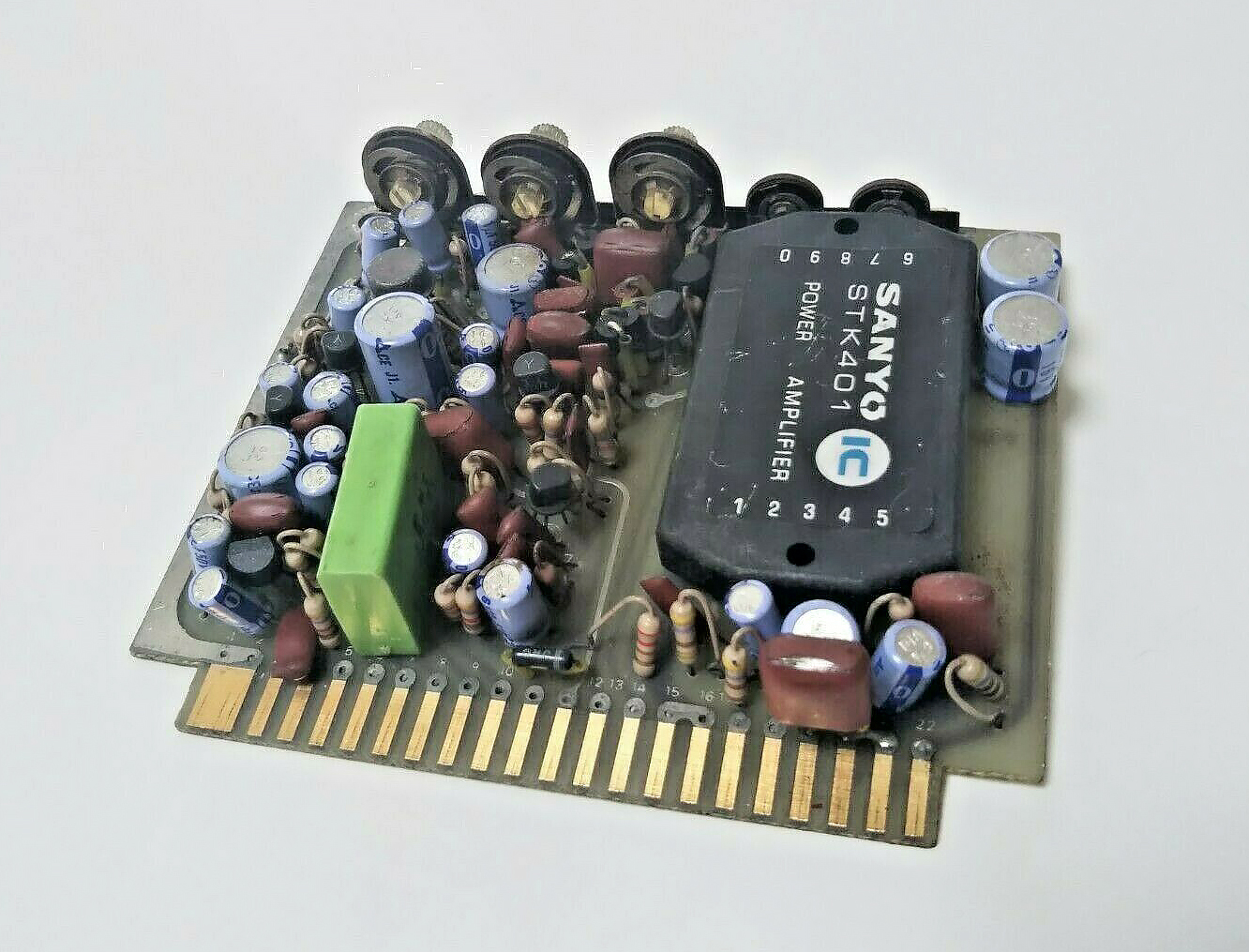
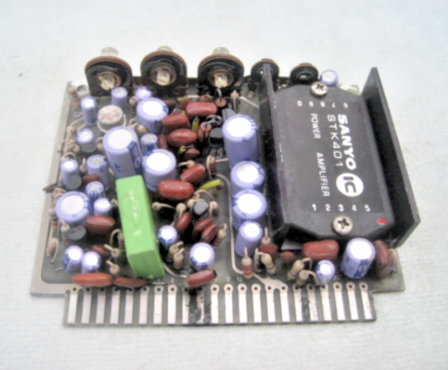
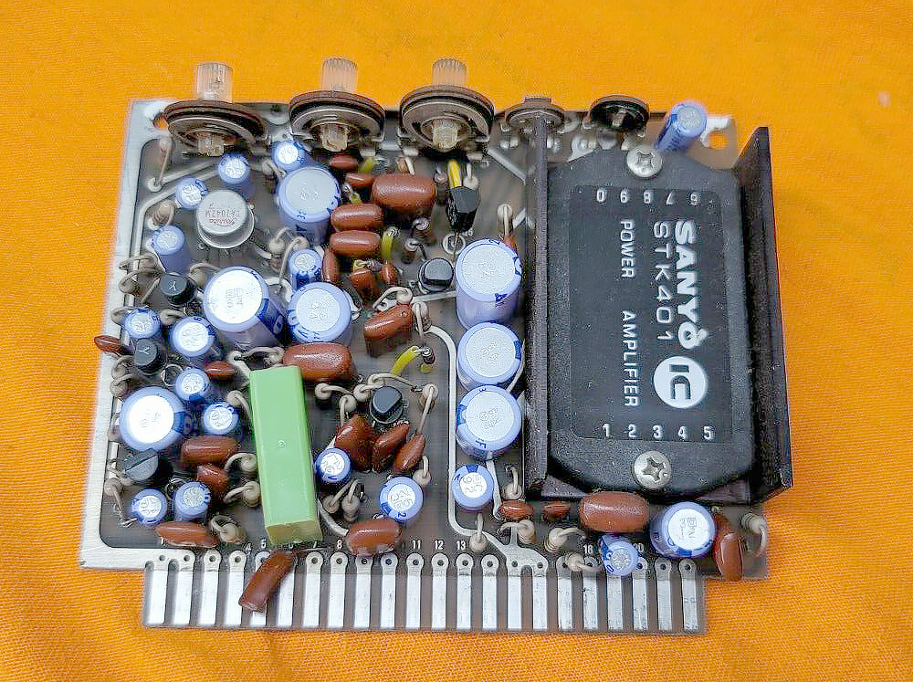
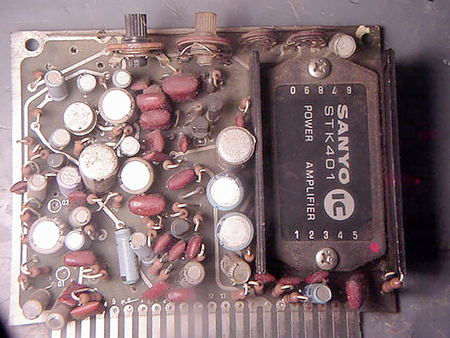
Photo of PB-1081C Audio Module installed into the Early model Yaesu FT-101 Transceivers
The Audio Module contains the Microphone Amplifier, Audio Amplifier, Vox and CW Side Tone generator.
One can easily note the difference from PB1081C which was used in the late production of the Yaesu FT-101 transceivers which came with the large Sanyo STK-401 Audio Amplifier IC and the later PB-1315A/B Audio Modules used in the newer Yaesu FT-101E and F model transceivers.
Very Early Yaesu FT-101 (MK-1) used an early audio board PB-1081B it has two (PNP 2SB463) transistors in push pull.
As noted below you will see Q10 and Q11 on the PB1081B Module.
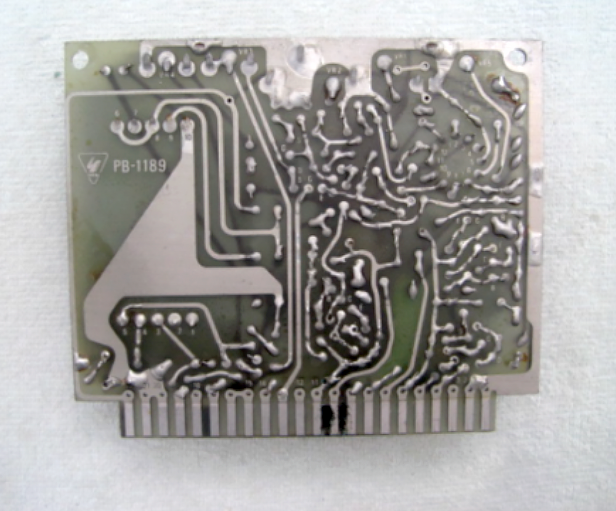
Upgraded Yaesu FT-101 (MK-1) transceivers used the Audio Module PB-1081C and then later models Yaesu FT-101 (MK-2) transceivers used PB-1189.
With the introduction of the Yaesu FT-101B the Audio Module changed again using the Audio Module PB-1315 in (Early) Yaesu FT-101B production.
All of these Audio Modules (except for PB-1081B) used the large Sanyo STK-401 Audio IC which was often a source of failure in the audio circuit due to oscillation problems.
It wasn’t until the Yaesu FT-101B(2) late production we were introduced to the improved Audio Module PB-1315A using the smaller AN-214 (4.4 watt) integrated circuit audio power amplifier IC.
Yaesu used the AN-214 audio chip in many of it’s amateur transceivers including the famous Yaesu FRG-7 Communications Receiver.
The AN-214 proved to be very reliable and the use of PB-1315A/B continued until the end 101 production.
Notes for Upgrading to a more modern Module such as the PB-1080B.
It is generally assumed you can not put a PB-1180B into a very early FT-101 which has PB-1084, this is true.
However you can put PB-1180B into an early unit if you cut the ground on Pin #14 under your early FT-101.
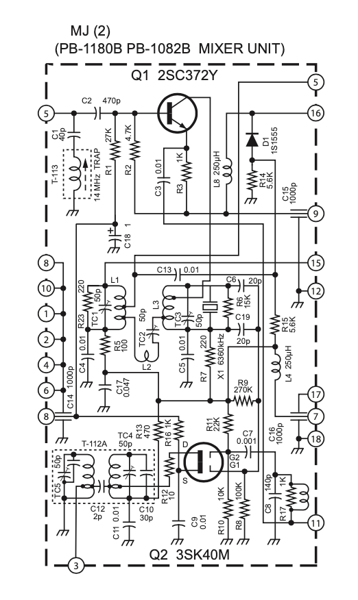
If you try to upgrade your early radio with PB1180B you will have no signal path as the ground on pin #14 of the early transceiver will short out your I.F signal path until the ground is removed from plug in socket MJ(2) Pin #14 which holds the mixer unit under the early FT-101 transceiver.
It can be done successfully and a newer High Frequency unit can be used in an early FT-101 by doing this step.
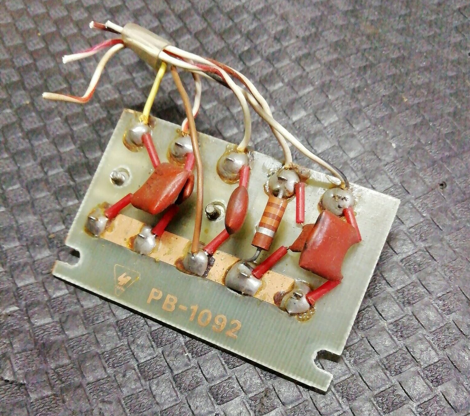
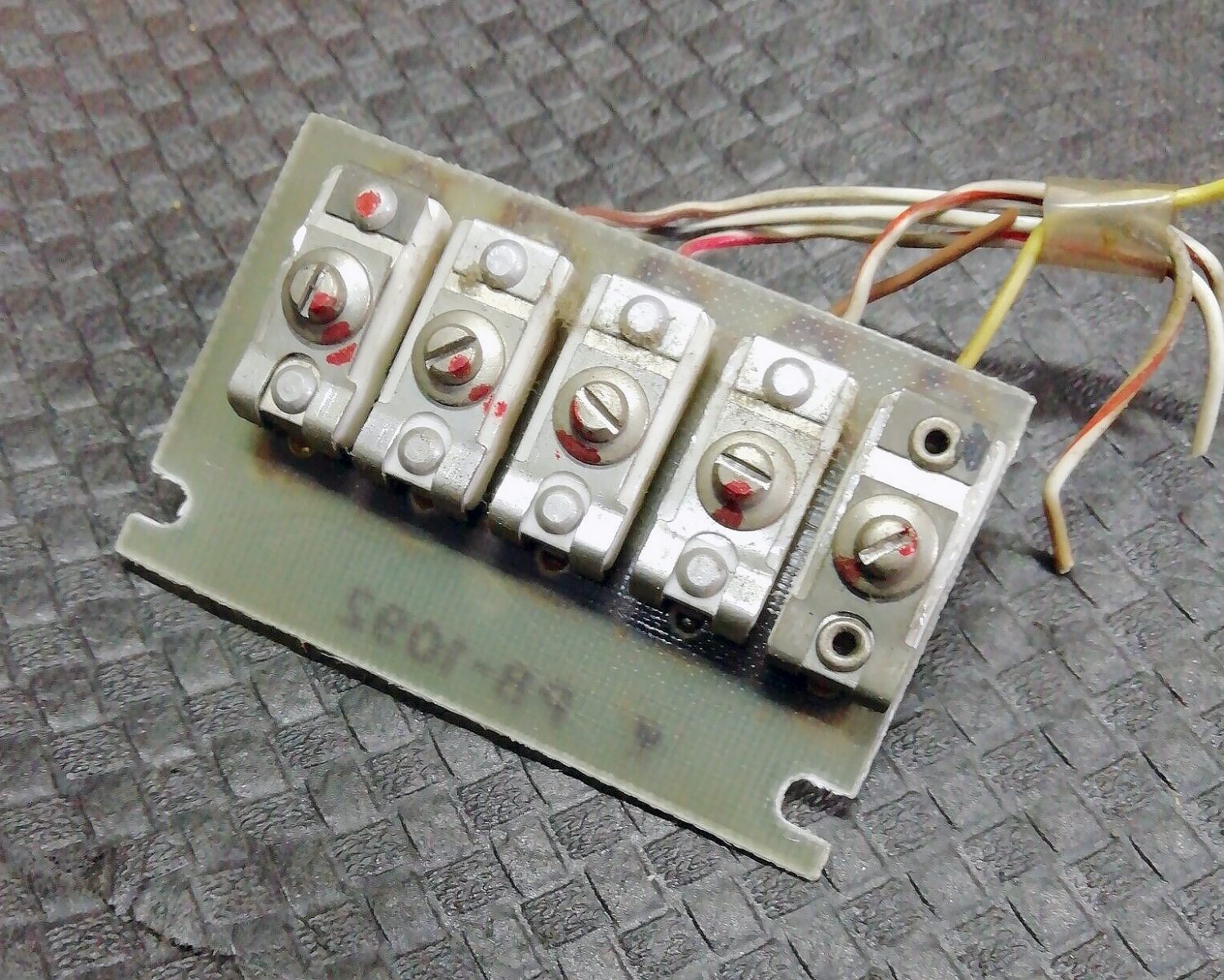
PB-1092 - Trimmer C Module
Photo of the PB-1092 - Trimmer C Module
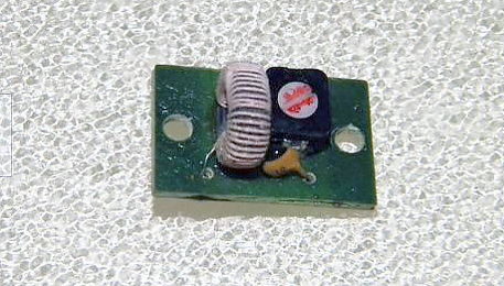
PB-1166 - Coil E Module
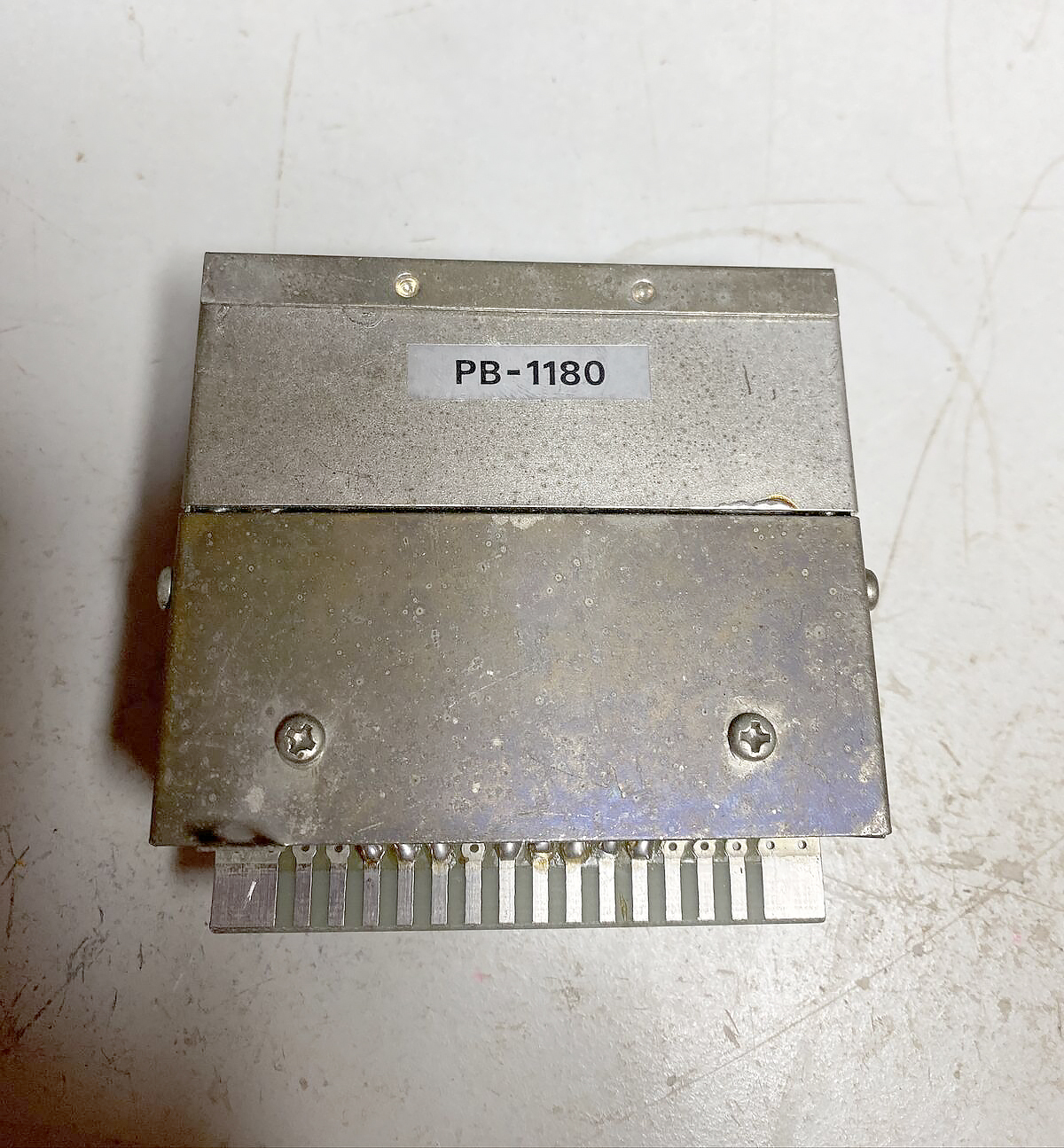
PB-1180 - High Frequency IF Module
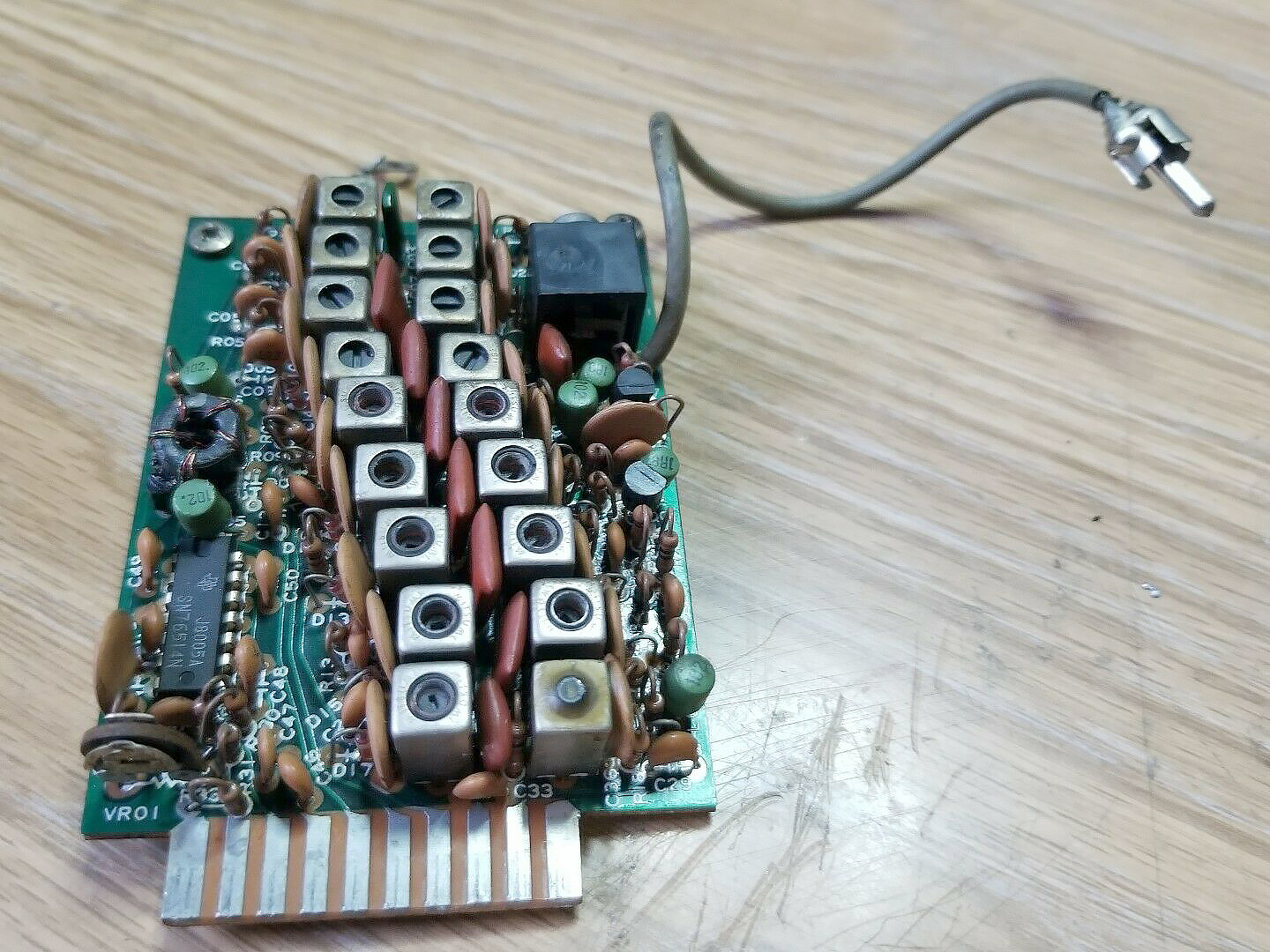
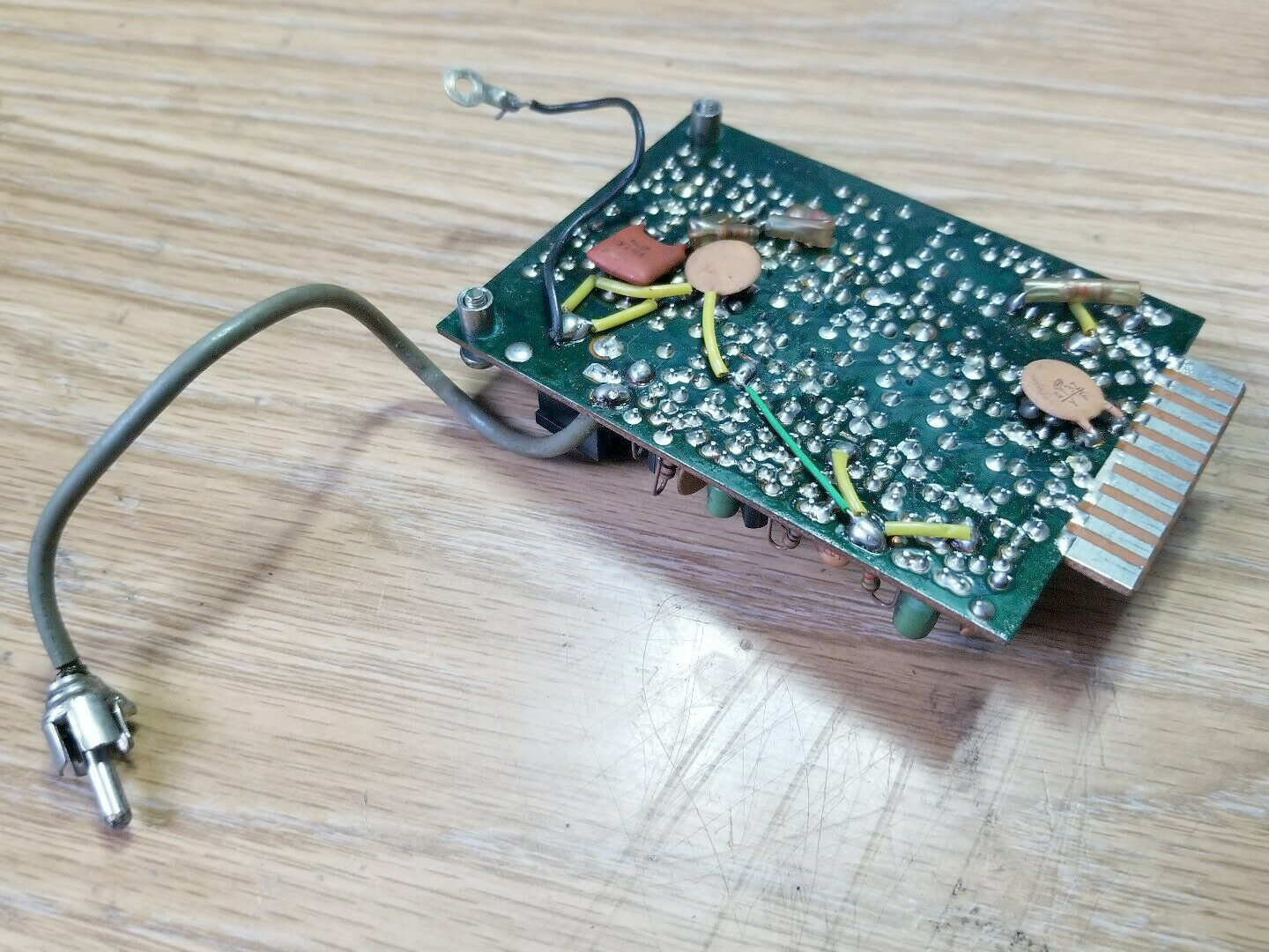
Photo of PB-1180 and PB-1183C High Frequency IF Modules
What you are looking at here is the PB-1180 High Frequency IF Module on the Lefthand side of this image next to the early unit PB-1083C High Frequency IF Module that is on the Righthand side of the image.
You will see clearly on the left image (PB-1180), there is a 6360 KHz crystal that is absent on the Early board.
This is part of a 6.36 MHz trap going out the circuit board to L32 via Pin #14.
It is generally assumed you can not put a PB-1180B into a very early FT-101 which has PB-1084, this is true.
However you can put PB-1180B into an early unit if you cut the ground on Pin #14 under your early Yaesu FT-101.
If you try to upgrade your early radio with a PB-1180B Module you will have no signal path as the ground on pin #14 of the early transceiver will short out your IF Signal path until the ground is removed from plug in socket MJ(2) Pin #14 which holds the Mixer unit under the early Yaesu FT-101 transceiver.
It can be done successfully and a newer High Frequency unit can be used in an early Yaesu FT-101 by doing this step.
A more recognised view of the PB-1180 High Frequency IF Module
PB-1180B - High Frequency IF Module
Photo of PB-1180B High Frequency IF Module
High Frequency IF Module PB-1180B
IF Unit: Transmit 1st Mixer and Receiver 2nd Mixer.
Photo of PB-1181B Front End RF Amplifier Module used in all of the FT-101B, and 101E Models
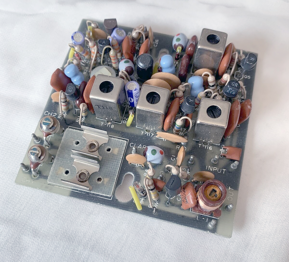
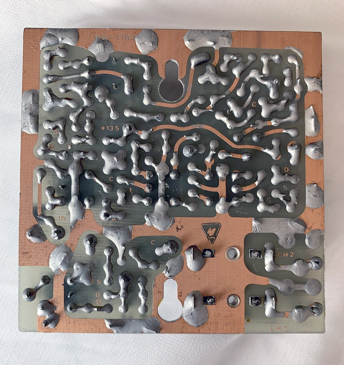
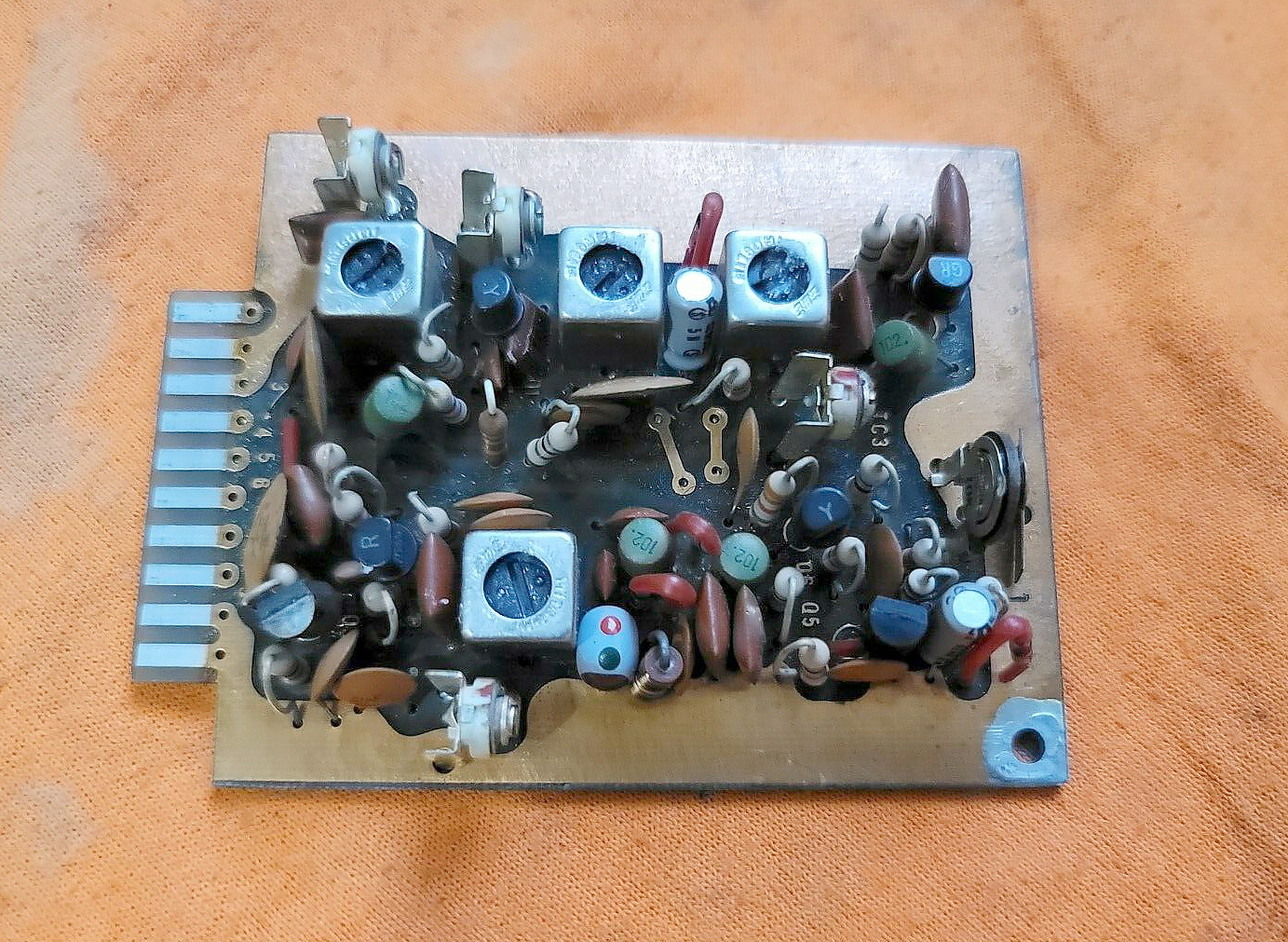
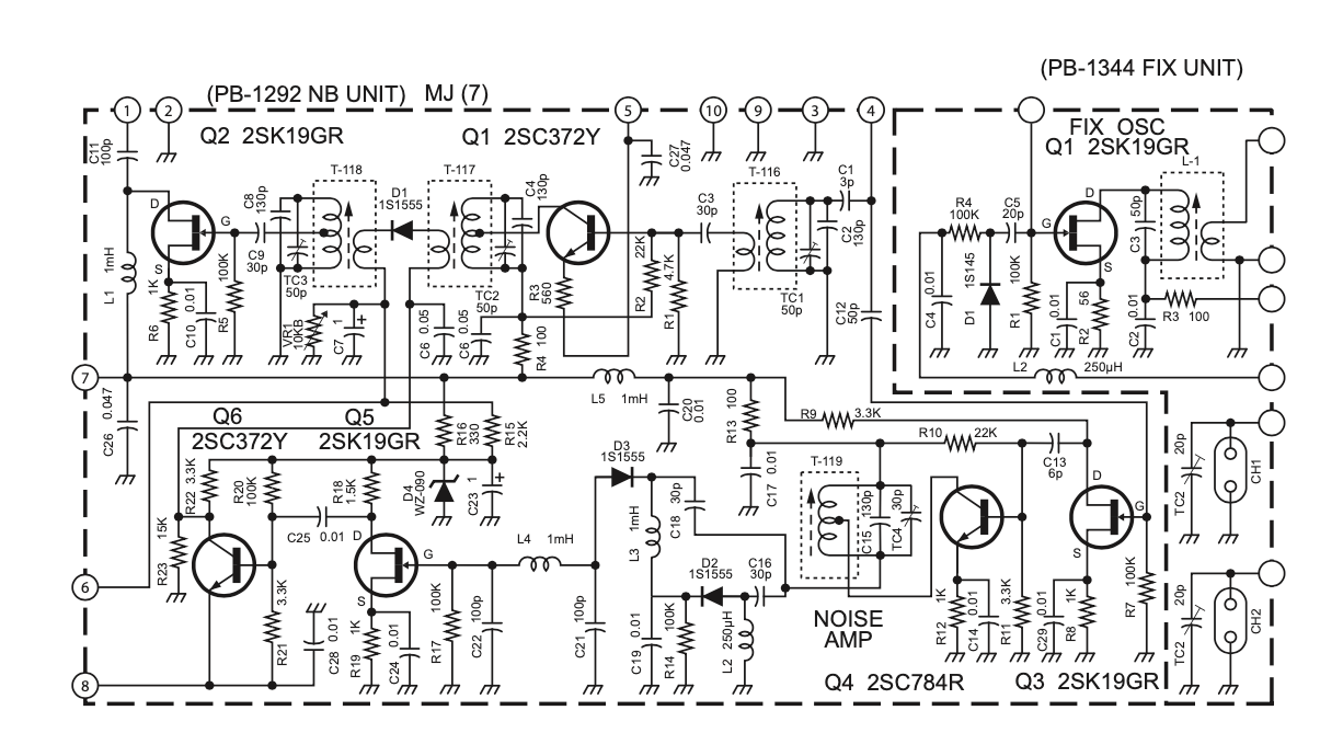
PB-1182 - Noise Blanker Module
Photo of PB-1182, the Noise Blanker Module that as fitted in the Early Yaesu FT-101 Transceivers
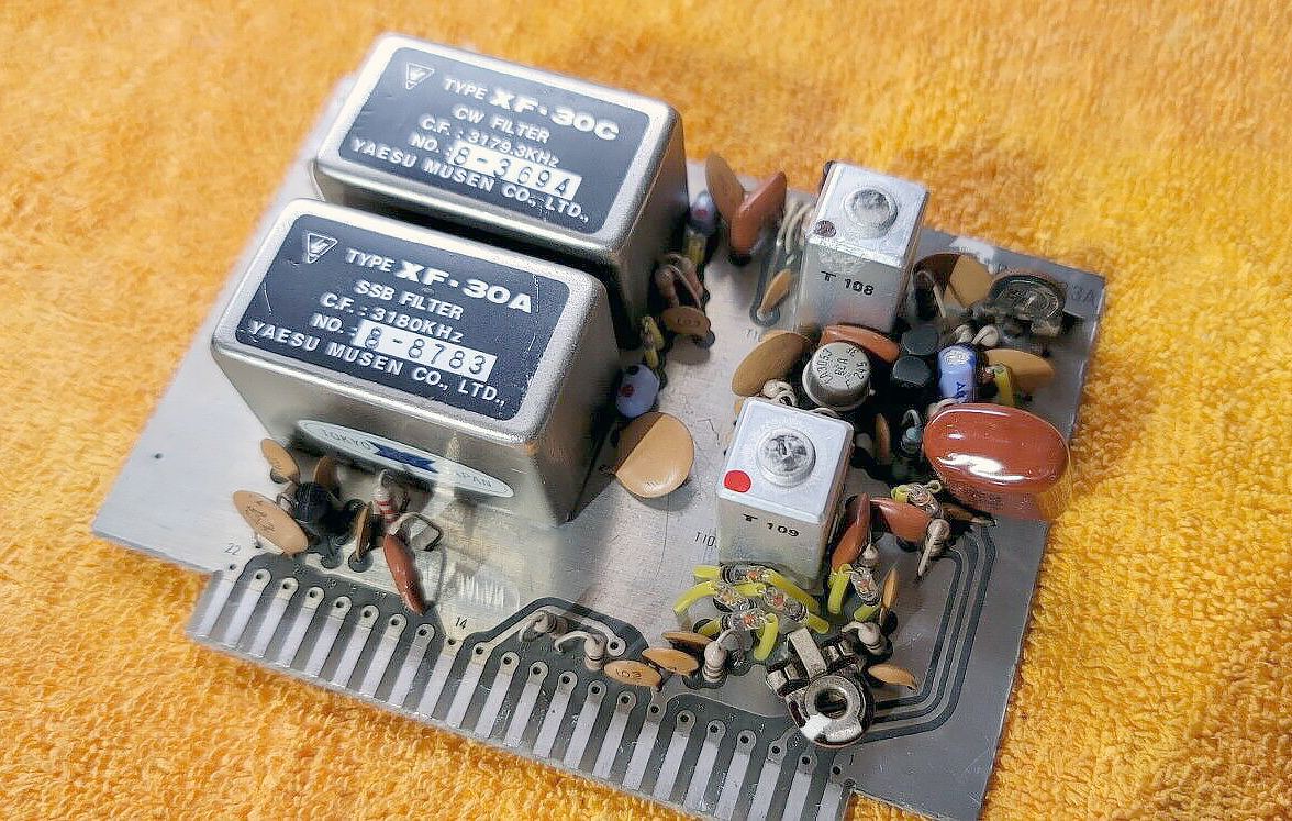
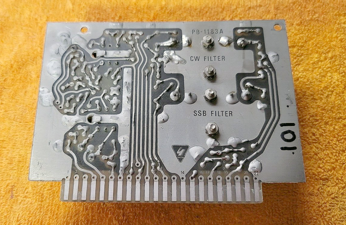
PB-1183A - Low Frequency IF Module
Photo of the PB-1183A - Low Frequency IF Module
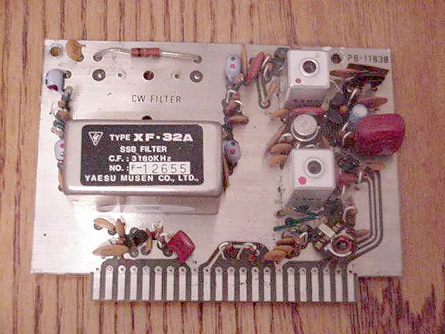
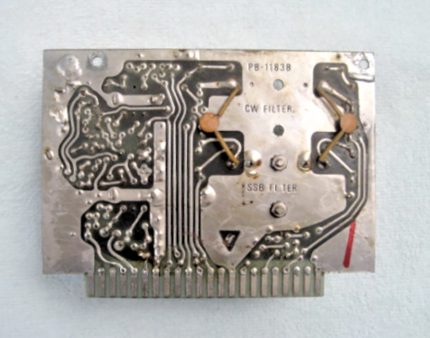
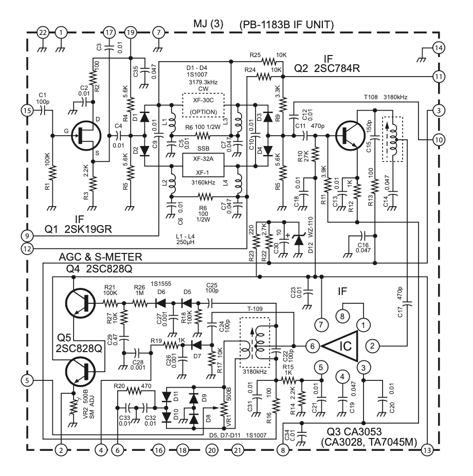
PB-1183B - Low Frequency IF Module
The Low Frequency IF Module PB1183B contains the Low Frequency IF Amplifier, SSB and CW crystal filters, detector and AGC/S meter circuits.
The 3180 KHz signal from the noise blanker is fed through this unit and the SSB/CW Filters through the Low Frequency IF Unit. In transmit mode, the IF signal is applied to high frequency I.F. unit from pin #10.
Photo of the PB-1183B Low Frequency IF Module used in most of the FT-101 Series
Photo of PB-1180 and PB-1183C High Frequency IF Modules
The PB-1183C High Frequency IF Module, which is the ‘Early’ board that is installed into Early Yaesu FT-101’s often referred to as Mk 1’s is on the Right of this image, The later unit which is the PB-1180 High Frequency IF Module is on the left and you can clearly see the 6360 KHz Crystal that is absent in this early board ‘PB-1183C which is part of a 6.36 MHz trap going out the circuit board to L32 via Pin #14.
Please Note:
It is generally assumed you can not put a PB-1180B into a very early Yaesu FT-101 which has PB-1084, this is true.
However you can put PB-1180B into an early unit if you cut the ground on Pin #14 under your early Yaesu FT-101.
If you try to upgrade your early radio with a PB-1180B Module you will have no signal path as the ground on pin #14 of the early transceiver will short out your IF Signal path until the ground is removed from plug in socket MJ(2) Pin #14 which holds the Mixer unit under the early Yaesu FT-101 transceiver.
It can be done successfully and a newer High Frequency unit can be used in an early Yaesu FT-101 by doing this step.
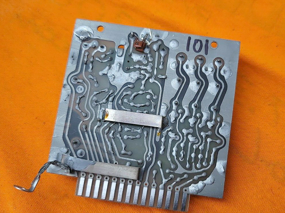
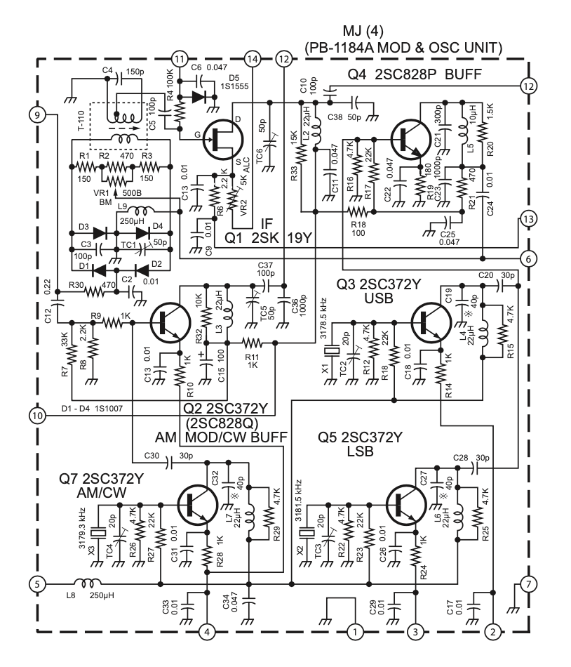
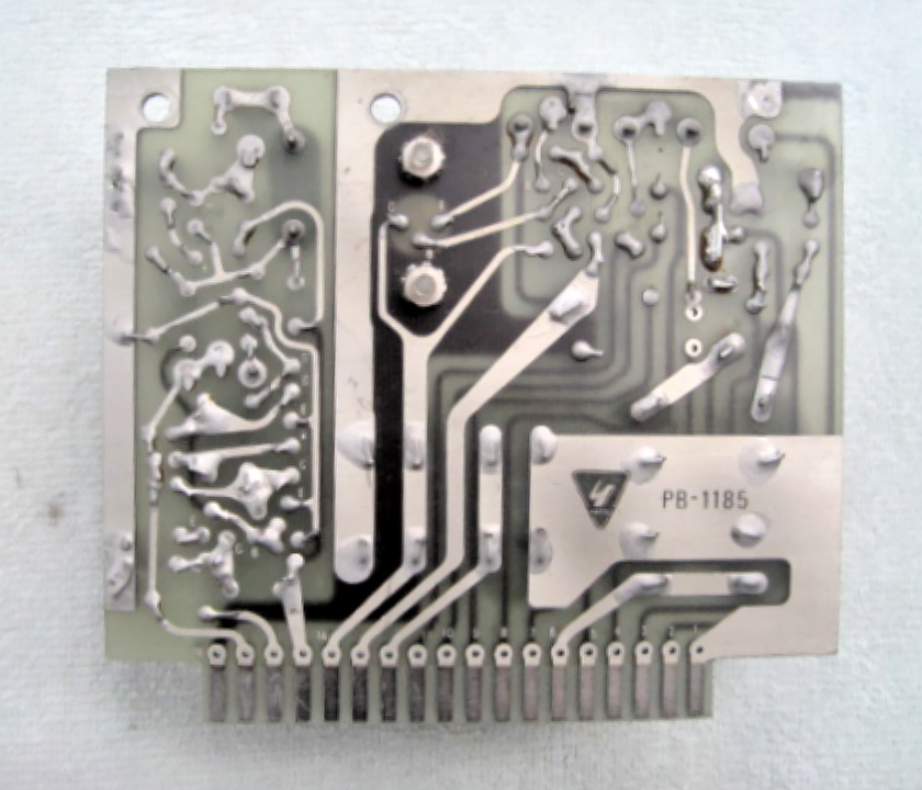
PB-1184 - Modulator Module
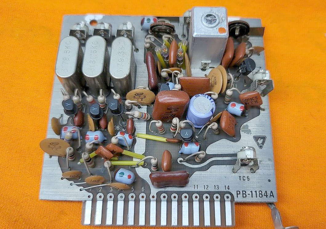
PB-1184A - Modulator Module
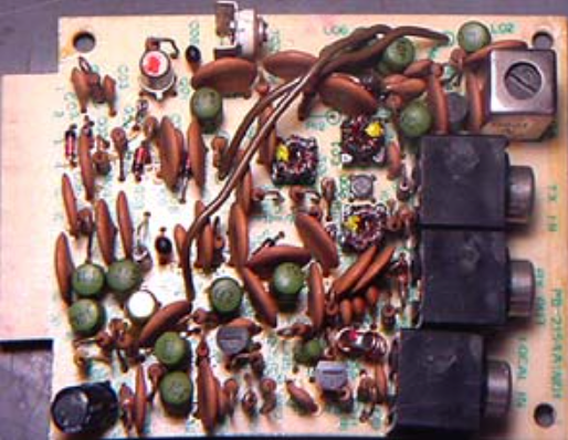
Photo of the PB-1184A Modulator Module that was fitted in the FT-101 Series of Transceiver
The Carrier Oscillator and Modulator Module has separate Oscillators for USB and LSB modes while CW and AM use the same Oscillator Crystal.
Except for a very few minor changes on this module, the Modulator module is one of the few boards which virtually remained the same through out the entire production of the Yaesu FT-101 Series of Transceivers.
There is really very little difference between a PB-1078A and a PB-1184A and there should be no reason what so ever that the two can not be interchanged, if needed.
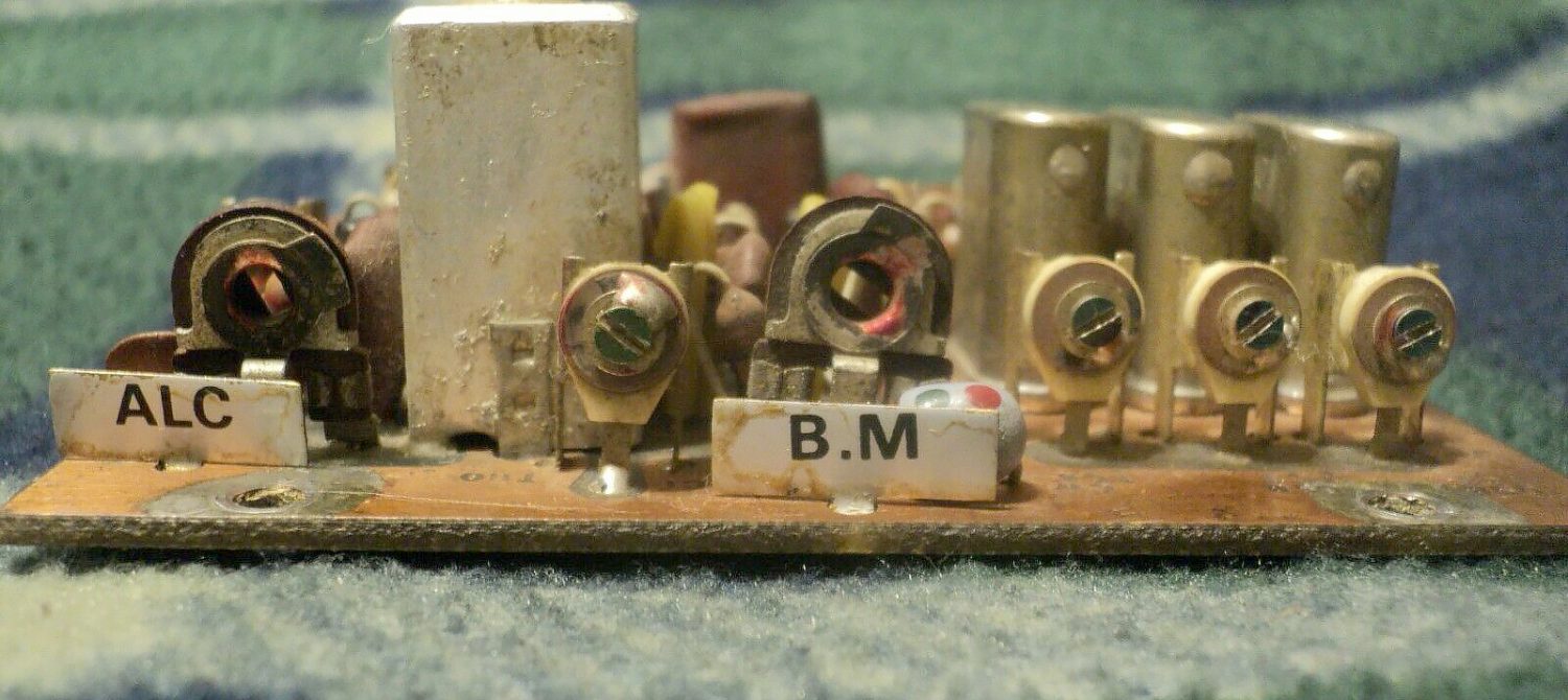
Close-up Photo of the PB-1184A Modulator Module that was fitted in the FT-101 Series of Transceiver
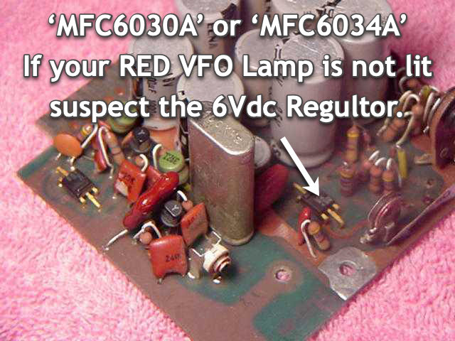
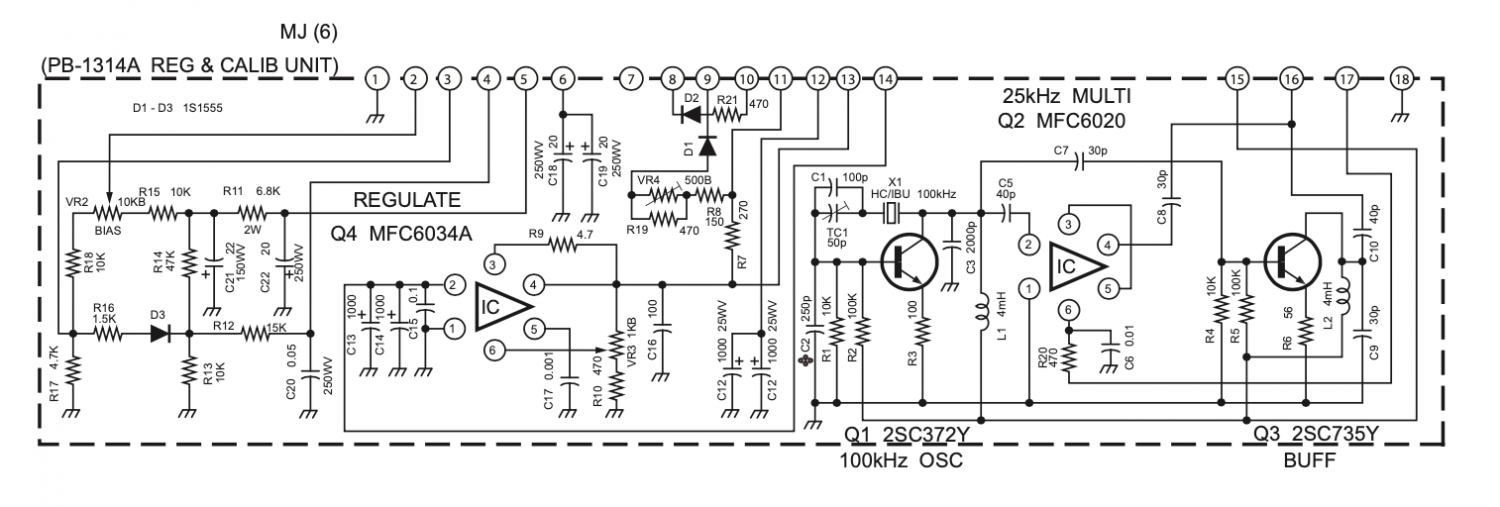
The PB-1314A is often seen in the Yaesu FT-101B ‘Late’ production and also in the Early Yaesu FT-101E Transceivers.
It uses a Voltage Regulator IC circuit in place of the two Bipolar Transistors seen on earlier modules to produce a regulated 6 volt DC supply.
This is one of the areas where we see the most change going on with this board throughout the years of the transceivers production.
The integrated circuit type MFC-6030A provided an extremely stable 6 vdc supply for the VFO and the Clarifier.
However through the years the MFC-6030A has become a source of failure on these Voltage Regulator modules and it can be difficult at best to find.
This unit can also be identified easily because it has the large 100 KHz HC-13U Crystal and the MFC-6020 integrated circuit multivibrator which generates a Marker Signal every 25 KHz.
The integrated circuits type MFC-6030, MFC-6032 and MFC6034A look identical.
Photo of PB-1315 Audio Module that was fitted in Early FT-101B's
The Audio Module PB-1315 that is installed in the Yaesu FT-101B (Early Models) looks similar to PB-1081C seen above with the addition of a heat sink on the STK-401 Audio Chip.
If you need to replace an STK-401 it has proven to be almost all but impossible to find at this late date.
You can use a NTE1151 may be used in its place.
PB-1315A - Audio Amplifier Module
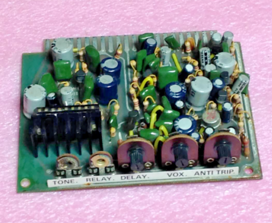
Photo of PB-1315A Audio Module that was used in Late Model B's and onwards
Used in the Yaesu FT-101E and F models transceivers.
This board replaced earlier versions and used the smaller 4.4 watt AN-214 9 pin single in line package, integrated circuit audio power amplifier chip.
Should you ever need to replace an AN-214 a suitable replacement is the NTE-1058.
The AN214 was used in most of Yaesu amateur products throughout the 1970s.
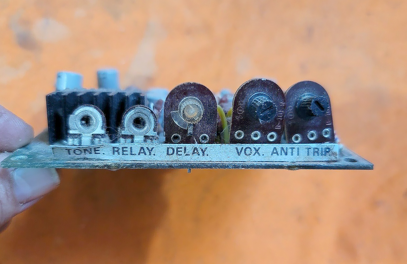
Photo of the edge of Photo of PB-1313A Module showing the adjustment pots.
PB-1315B - Audio Amplifier Module
Photo of the PB-1315B Audio Amplifier Module that was only fitted in the FT-101F Models.
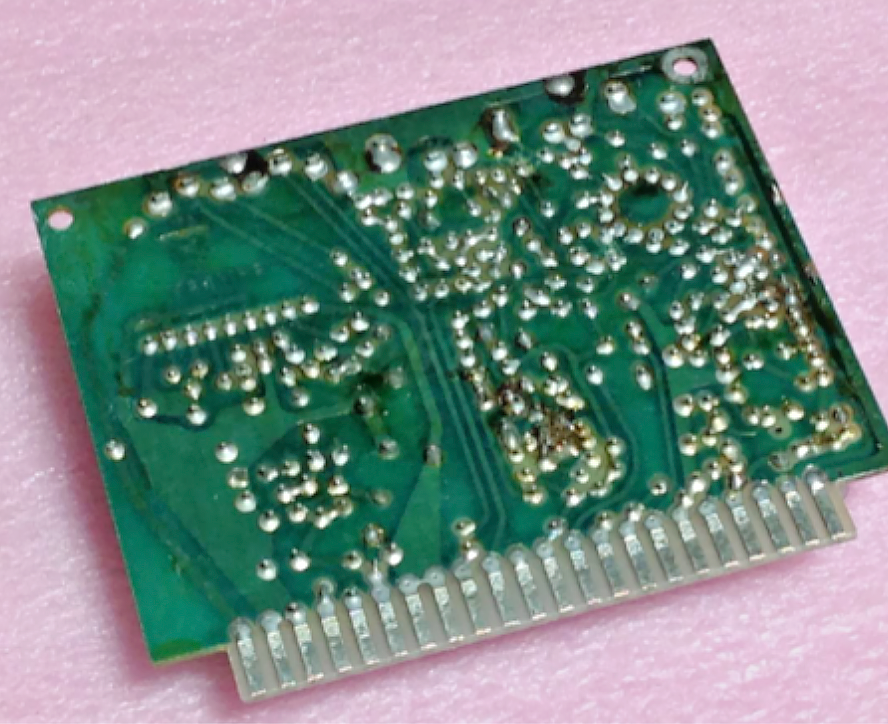
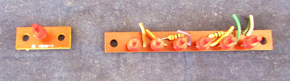
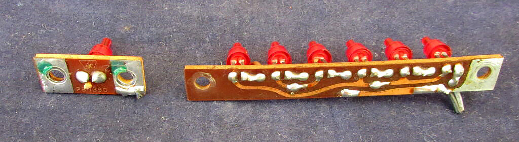
PB-1390 - Lamp Module
Photo of PB-1390 Lamp Module used in the FT-101ZD Transceivers
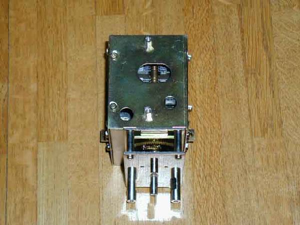
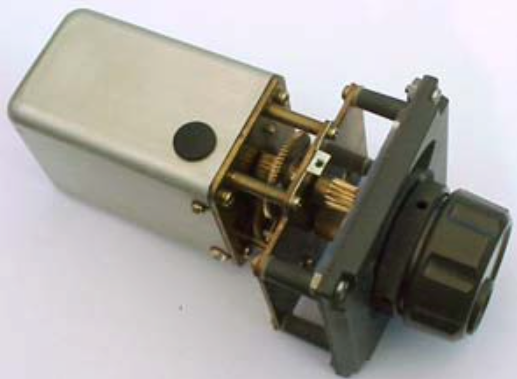
PB-1440B-3420 - VFO Module
Photo of PB-1440B-3420 VFO Unit
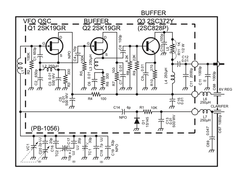
The VFO uses a modified Colpitts type Oscillator to generate a 5-5.5 MHz VFO Signal, producing a 500 KHz tuning range.
The VFO tuning is extremely linear over the entire range.
Stability is very good, and tuning is very exact with the smooth precision gears.
The VFO is one of the reasons for the good stability of the transceiver.
The VFO frequency can be carried by a small amount, providing an offset of +/- 5 KHz, by a Varicap diode and a controlled voltage. (Clarifier), very useful when you are in a net, when all members are not exactly on the same frequency.
This VFO unit was used in all of the FT-101ZD transceivers and also the later FT-901DM Transceivers.
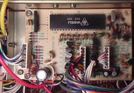
PB-1494 - Processor Module
PB-1534 - Processor Module
PB-1534A - Processor Module
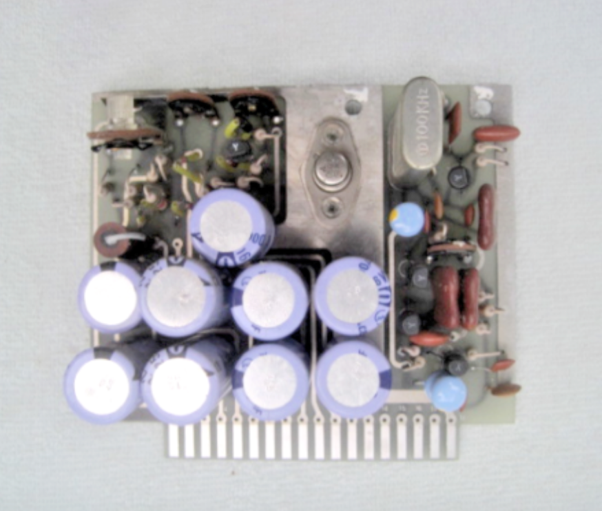
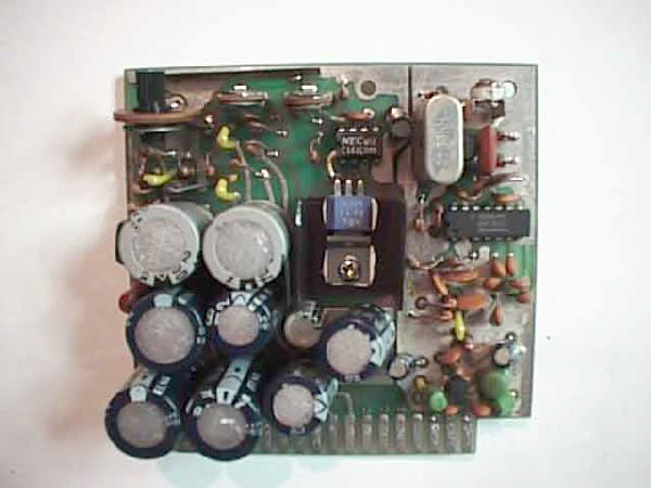
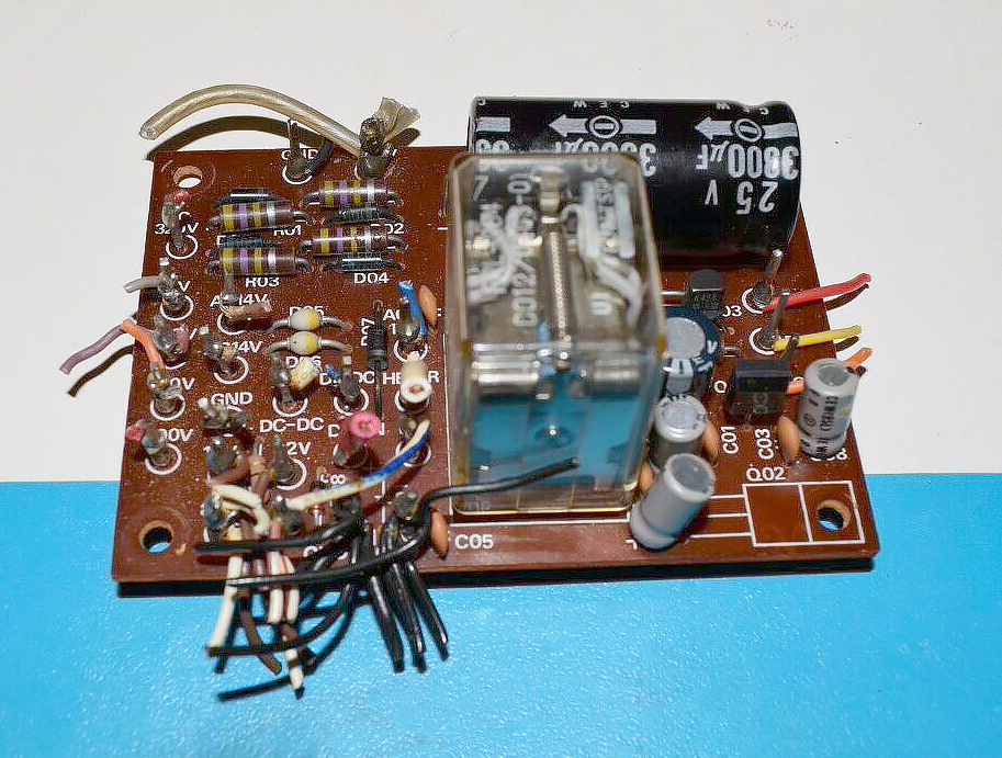
PB-1547 - Power Regulator Module
PB-1574A - Power Regulator Module
Photo of PB-1547A Power Regulator Module
The PB-1547A Power Regulator Module was the final and best power supply circuit board produced by Yaesu for this series of Transceiver.
It sported a regulator circuit comprised of Q1, uPC141C, and Q2 (2SA634) for an extremely stable 6 volt DC supply which is fed to various circuits from pin #13 of it’s board.
This board also had the latest Marker Signal Generator using a 3200 KHz crystal frequency signal that is divided into 100 KHz and 25 KHz marker signals which was then fed to the receiver antenna circuit.
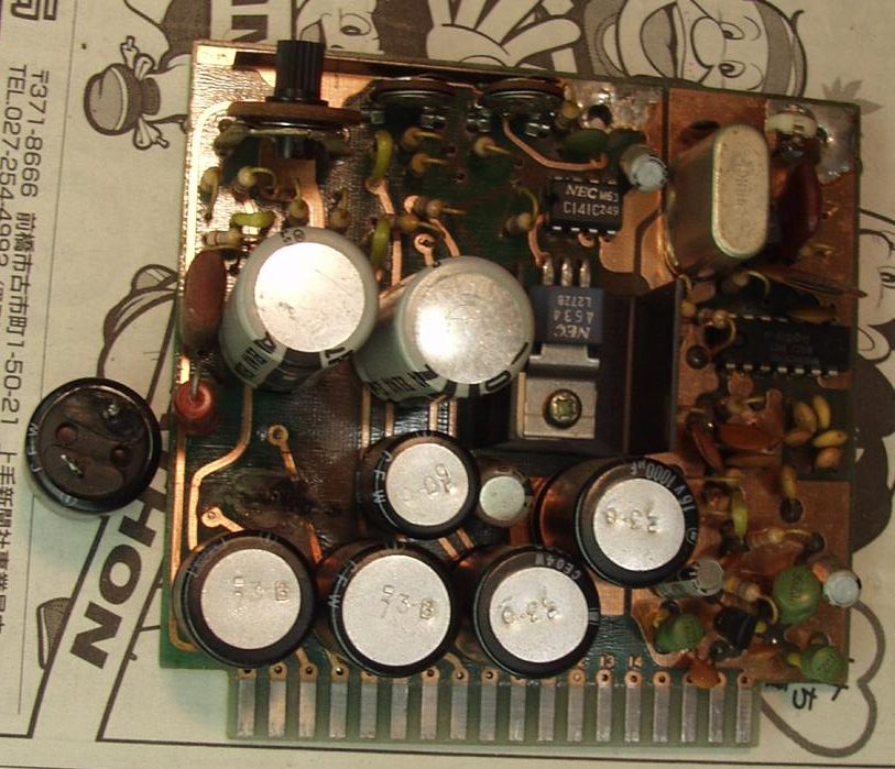
Photo of PB1574A Power Regulator Module with a Blown Capacitor.
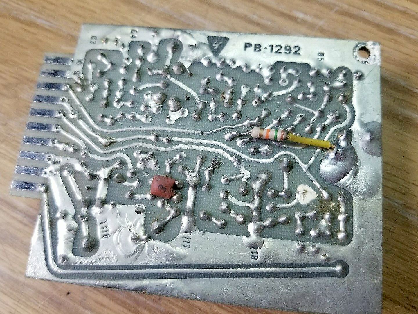
PB-1582 - Noise Blanker Module
Photo of PB-1582 Noise Blanker Module as used in the Ft-1012E Late Models
PB-1582B - Noise Blanker Module
Photo of PB-1582C Noise Blanker Module
The PB-1582C Noise Blanker Module receives 3180 KHz to the noise blanker unit.
Very early Yaesu FT-101 Series Transceivers had the Noise Blanker circuit on PB-1080A.
Later models in the series FT-101/B/E/F had a plug in Noise Blanker boards such as PB1182, PB1292 and PB-1582.
PB-1714A - 12BY7A Driver Module
The PB-1714A Driver Module used in the FT-101ZD for the Driver Vacuum Tube 12BY7A.
The driver board amplifies the SSB/CW signal and feeds it to the PA.
The driver uses a tube (12BY7A) for delivering the neccessary power, and the tube is also used in the automatic level control circuit (ALC).
Part of the output is available at a connector at the back, for use with transverters or other purposes.
It delivers 3V RMS into 50 ohms.
Tuning is done with the same inductive tuning unit, that is used by the RF board.
The inductive tuning allows a constant output over a greater range.
The heater of the tube is switched by the heater switch on the front. Using this switch during longer receiving-only periods, the tube will last much longer, and there is less heating up. Warming up time for the tube is abouth 60 seconds.
If you have lower output from the PA, check this tube first.
PB-1715A - Power Amplifier Final Module
The Power Amplifier, consists of two 6146B heavy duty transmitting tubes, the input filter and the output filter.
The output filter delivers the RF signal to a suitable antenna.
The impedance from the antenna has to be between 50 and 75 ohms unbalanced.
A Antenna with a different impedance at the feedpoint can be used, but there must be a matching device between the transceiver and this feed-point.
The same goes for other antennas with a lower impedance such as magnetic loops and others.
The 6146B PA tubes are very rugged, and can deliver around 100 -120 Watts output depending on the band of operation, by a input of 180W in the SSB and CW mode.
In AM mode the maximum input power is 45 Watt.
This is due the fact that the SSB signal has just one sideband, which has only 25% of the power factor of a AM signal, so the tubes can deliver in SSB 4x the power of a AM signal, at the same dissipation.
It is never a good idea to push the PA to the limit, it is much better to run the PA with powers around 150W input in SSB/ CW, the tubes will last much longer, and the difference at the receiving station is minimal.
You will be surprised how many DX stations can be worked with low power.
It all depends on an effective antenna, band conditions and operating skill, and not only big power: you have to double your power output to make a S-point difference at the receiving station!
A good antenna is a better investment than big power: It works 2-ways, you even hear the station coming back to you:).
6146 Series Vacuum Tubes
There are several different types of 6146 tubes, and, now tubes are getting scarce is it good to know what possibilities there are for replacing the tubes with others.
The FT-101ZD uses the 6146B type, which has the biggest dissipation, thus the biggest output, but has a bad reputation for VHF oscillation and TVI as result.
They must be very good neutralized, otherwise the PA destroys itself. The basic 6146 and 6146A (same tube, with a sturdier heater) is still around in great numbers an can be used if there are no 6146B’s available.
The only drawback is the lower power capacity: the anode dissipation is 25% lower and they need a new neutralization and a correction of the bias voltage.
Another tube is the 6146W, a military designation, used as a remplace for 6146, 6146A and 6146B in the forces. This tube has a rugged construction, similar to the 6146B, but the saying goes that the input power on this tube should also be reduced to ca 75% of the nominal output of the 6146B. 6146 and 6146A may be mixed, but never mix a 6146(A) with a 6146B, because you are in for very strange effects, and some fireworks.
PB-1960A - Front End RF Module
PB-1960A - Front End RF Module
Contains the RF pre-amplifier, the receiver and transmitter mixer and a buffer stage, the Mixer output of 8.9875 MHz goes to the IF board.
The In and Output tuning of the RF amplifier is done by permeability-tiuned circuits resulting in high sensitivity and excellent rejection of unwanted out-0of-band signals.
The difference between this board and the newer version that was installed into the FT-101ZD Mark 2 and Mark 3 units is the Mixer.
This board uses a balanced mixer with 2 FET’s, the later board (PB-2154A) uses a diode ring mixer for better big signal behaviour.
This Module is The FT-101ZD Mark 0 and FT-101ZD Mark 1.
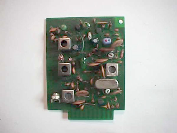
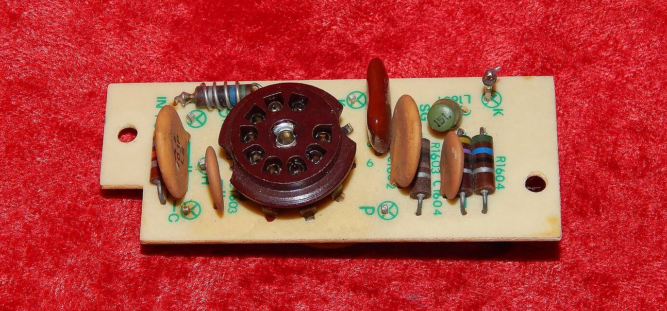
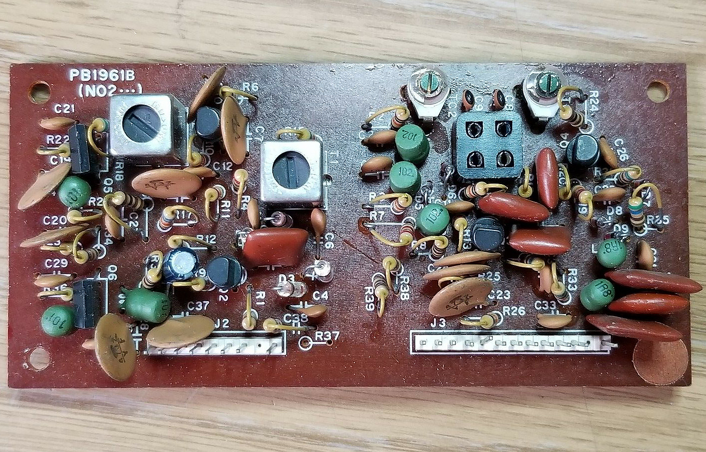
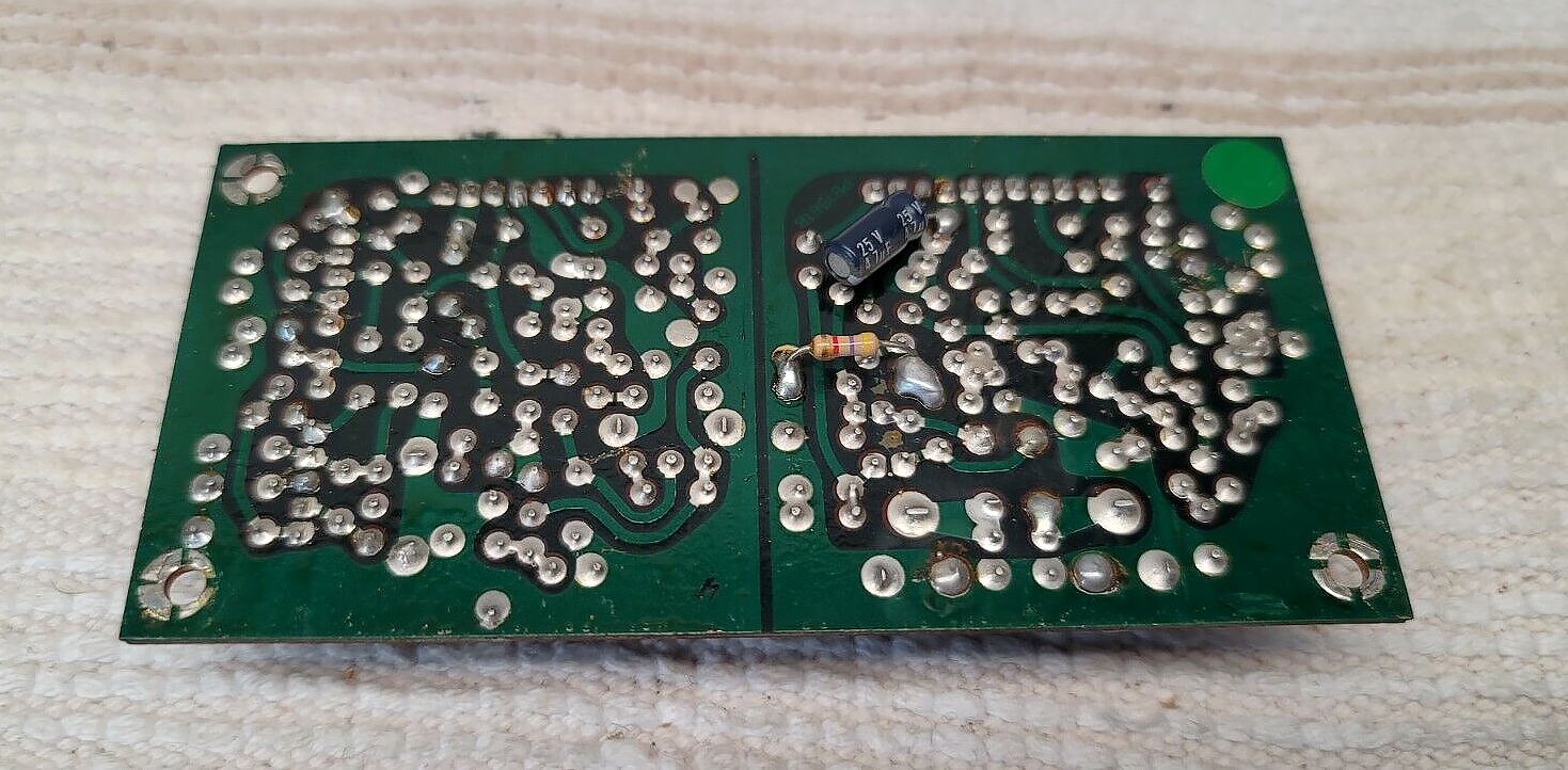
PB-1961B - Noise Blanker Module
Photo of the PB-1961B Noise Blanker Module used in The FT-101ZD Series.
This Module is used in every version of the FT-101Z. and contains the ‘Noise Blanker’ circuitry and a Crystal (X-tal) Oscillator for 2 fixed frequencies.
The fixed frequencies are sideband dependent, so the operating frequency is on LSB 3 KHz higher than on USBN at a given X-tal frequency.
The necessary X-tals have to be in the VFO (5-5.5 MHz) orange.
This Module is used in every version of the FT-101Z.
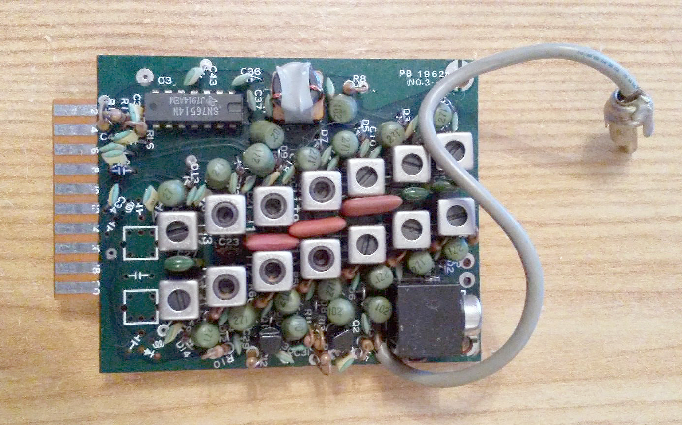
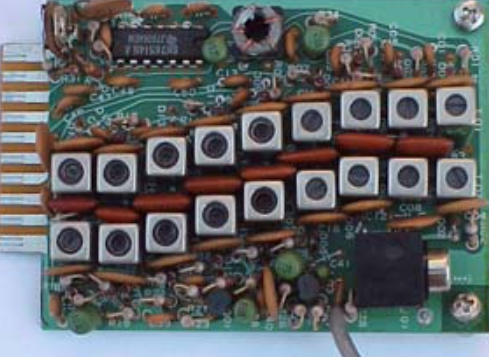
PB-1962A - Pre Mixer Module
Photo of the PB-1962A - Pre Mixer Module used in the FT-101ZD
The Pre Mixer Module mixes the signal from the Premix Local unit with the VFO or Crystal controlled signal in a double balanced mixer.
The premix signal is passed through a band pass filter and delivered to the RF unit.
This is the older board, this was later replaced with the newer PB-2152 which has 9 filters for coverage on all amateur bands.
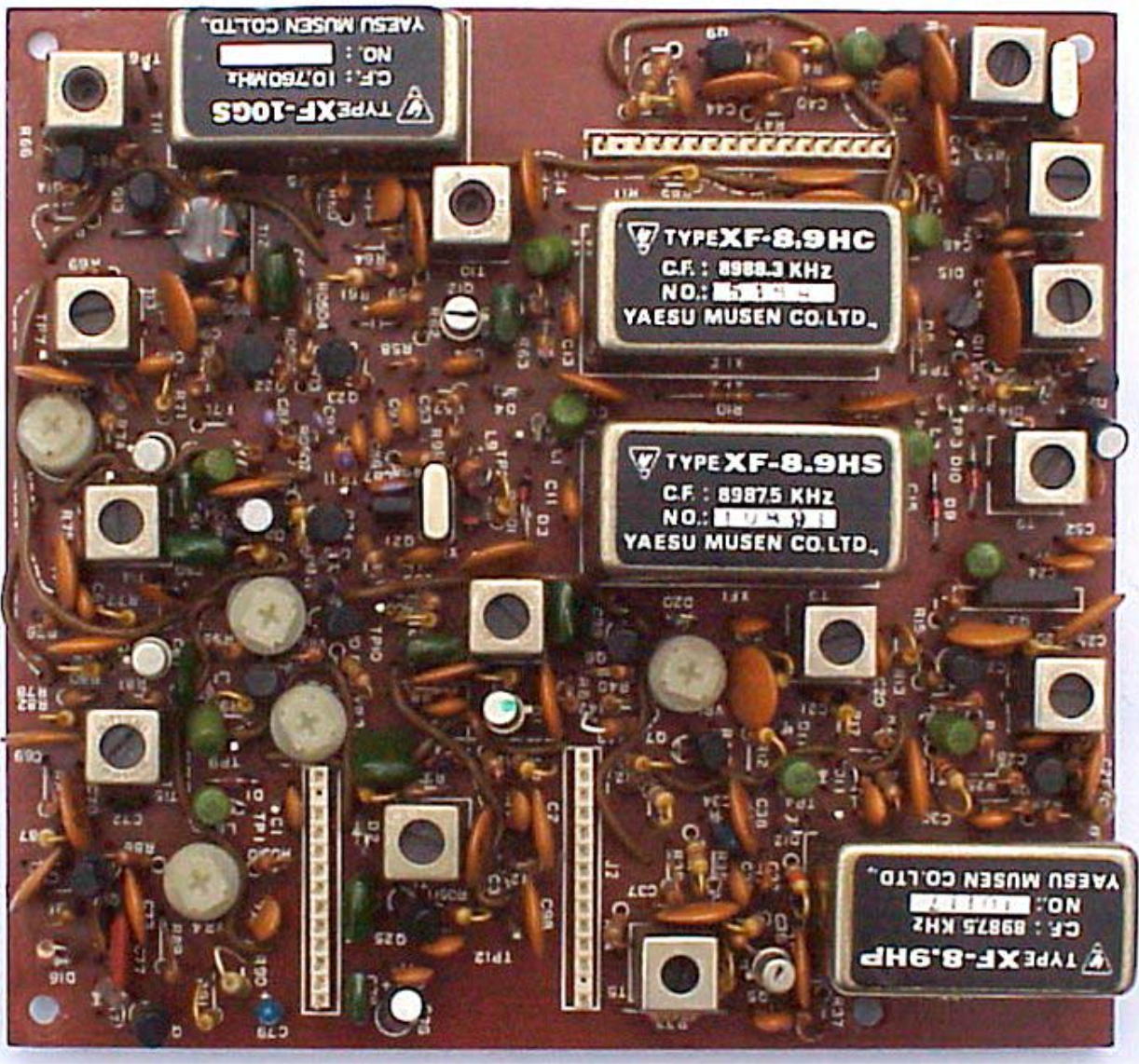
PB-1963B - IF Module
Photo of the PB-1963B IF Unit found in the Yaesu FT-101ZD
The IF Module is the heart of the transceiver and is the same in every type of FT-101ZD, although there does seem to be two revisions of this Module, the PB1963B and the PB-1963C, although no differences can be seen between the two at this time.
The signal is first passed through a monolithic filter with a bandwidth of 10 KHz to have a wide band point of noise blanking.
The signal then passes to the Noise Blanker gate and is fed through the SSB filter our the Optional CW filter to the IF’s First Mixer.
Here the incoming signal is Hetrodyned with a 19.7475 MHz local signal.
This local signal is delivered from a XCO and the resulting mixing frequency is 10.76 MHz.
This 10.76 MHz signal is fed through a second SSB filter, and mixes with a Vericap over a close range, and a result is that the passband of the first ands second filter shifts along each other, so in affect making the passband smaller or larger, depending on the frequency of the XCO.
It is a very useful item, you can make the band pass as low as 300 Hz, and as high as the original pass band of the first filter (SSB 2.4 KHz, CW 300 Hz or 600 Hz).
The skirt of the filters add, so the filter pass band improves too.
The output from the second IF mixer is fed to a 2 Stage IF amplifier and is delivered to the AF Module.
On the board are also the AGC amplifier and the Signal Meter amplifier, the SSB TX IF Filtering and the Speech Processor with Filter.
The board has the SSB filter installed, and there is room for installing a 300 Hz or 600 Hz CW filter (XF-8.9HC).
This Module is used in every version of the FT-101Z.
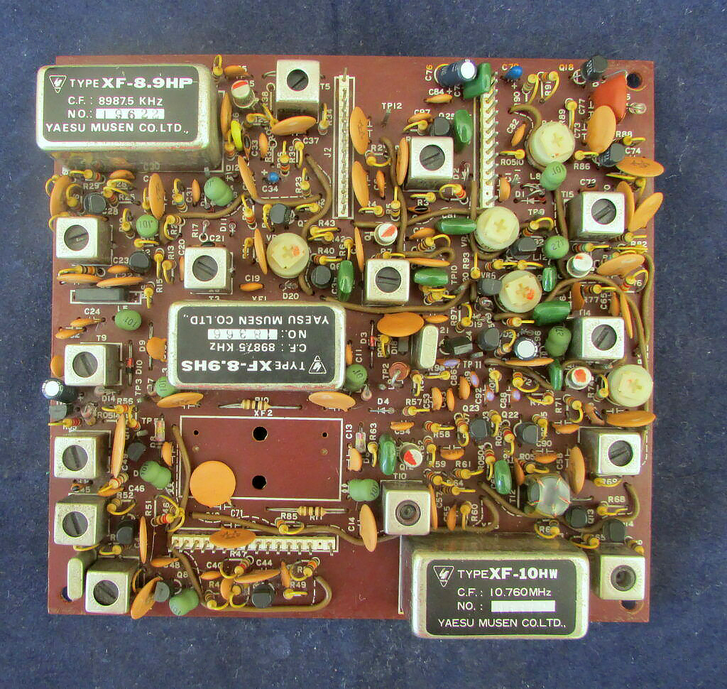
PB-1963C - IF Module
Photo of the PB-1963C IF Unit found in the Yaesu FT-101ZD
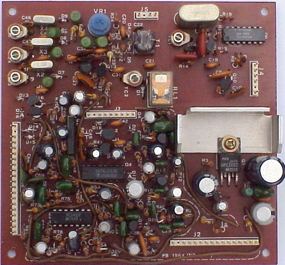
PB-1964 - AF Module
Photo of the PB-1964 AF Module.
The AF Module contains the SSB/CW diode ring demodulator and the carrier oscillators:
USB/CW (rx): 8989 KHz
LSB: 8986 KHz
CW (tx): 8988.3 KHz
The audio signal is amplified and delivered to the internal or external speaker.
On the AF Module is also the Marker generator which provided a 25 KHz Marker signal for alignment and testing purposes.
The Transmit Microphone Amplifier with Sideband generator and a 800 Hz sidetone generator for CW are also a part of the AF Module.
This Module is used in every version of the FT-101Z.
PB-1964A - AF Module
This module has 10 Crystal Oscillators which are selected by Diode switches, they generate the Premix Local signal for each of the amateur bands plus the WWV.
It is possible to add another band on the board, by adding the necessary components and re-wiring the band switch.
The local signal is then delivered to the Pre Mixer Module.
PB-1965 - Premix Local Module
Photo of the PB-1965 Premix Local Module used in the FT-101ZD Mark 0 and Mark 1 Transceivers.
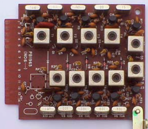
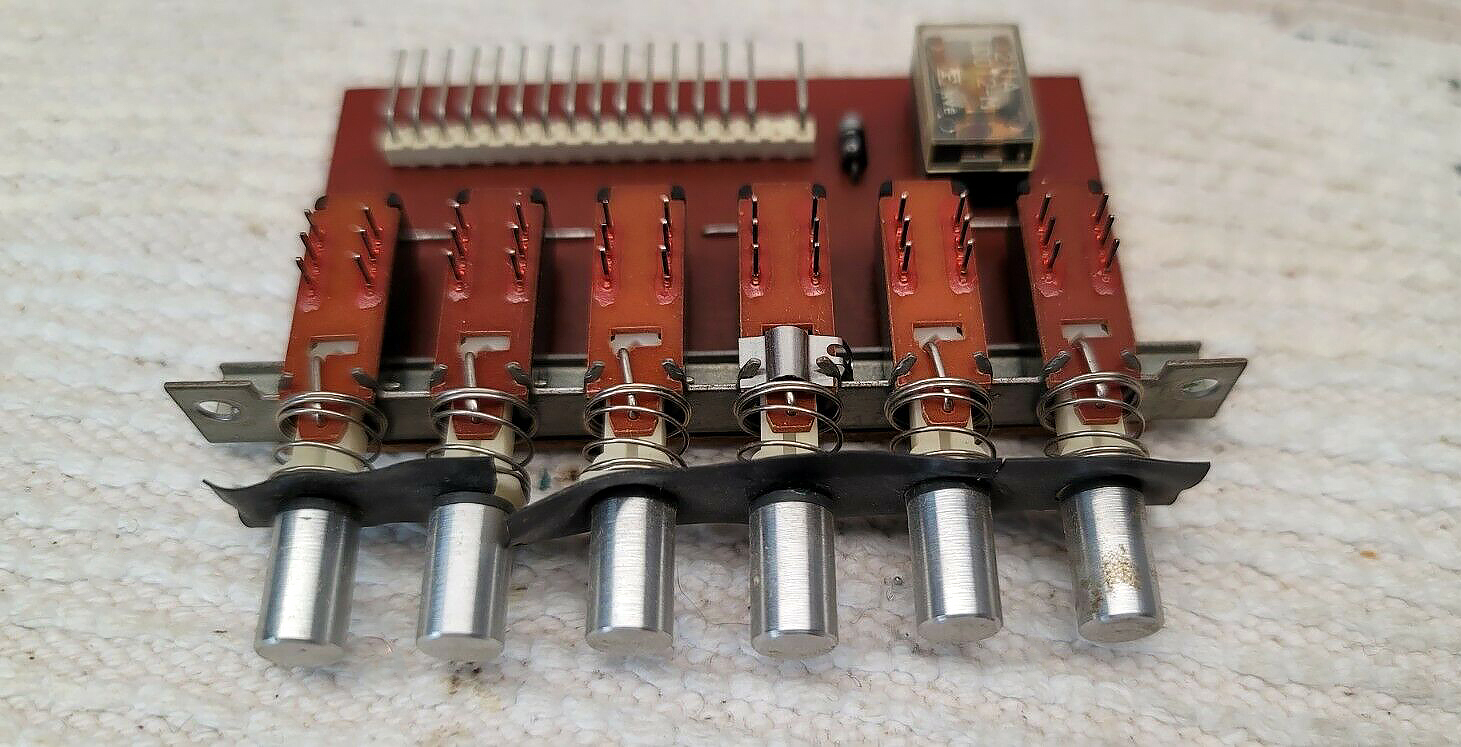
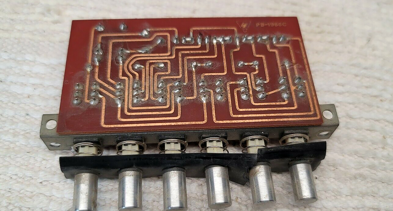
PB-1966C - Selection Switch Module
Photo of the PB-1966C Selection Switch Module
PB-1967 - Power Supply Rectifier Module A
Photo of PB-1967 - Power Supply Rectifier Module A
This board delivers all the high and low voltages used in the transceiver, so be careful, there are points with 900 Volts dc on this board, and that voltage can do serious damage to a unsuspecting Ham to say the least.
Unload always the condensors, preferabely with a resistor, before starting to work at this circuits.
The board is positioned in the underside of the transceiver and delivers the various low voltages (6, 8, 12 Volt dc) and the 900Vdc for the Power Amplifier.
This board is used in all models of the FT-101ZD.
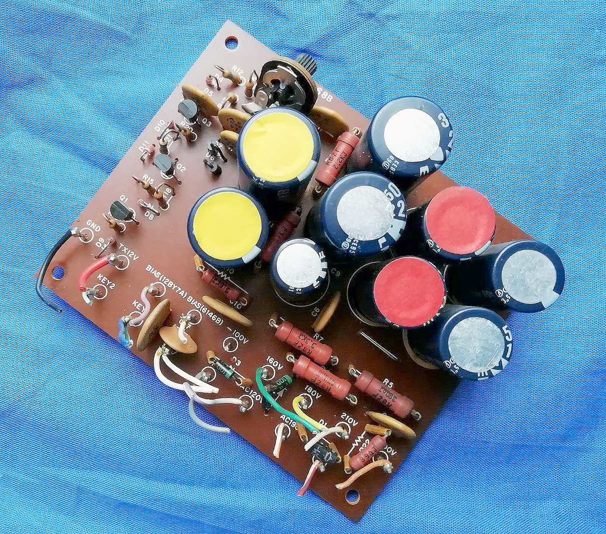
PB-1968A - Power Supply Rectifier Module B
Photo of PB-1968A - Power Supply Rectifier Module 'B'
There are two versions of this board found in all models of the Yaesu T-101ZD transceiver, although no differences have yet be found between the A and B model PCB’s.
This board delivers the bias voltages of the PA unit, the 150, 160, 200 and 300 Vdc for the driver and Power amplifier. This board is mounted at the left side of the transceiver.
On this board is also the CW keyer circuit.
The board is used in all models.
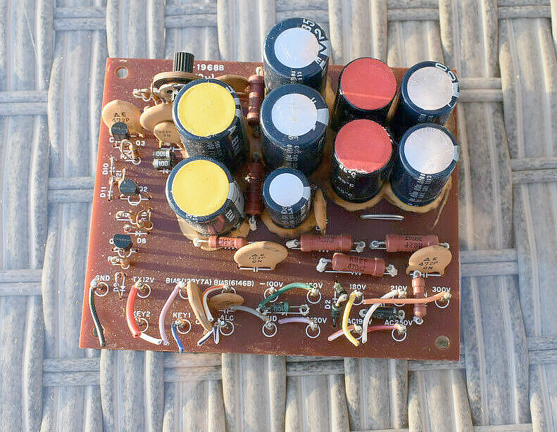
PB-1968B - Power Supply Rectifier Module B
Photo of PB-1968B - Power Supply Rectifier Module 'B'
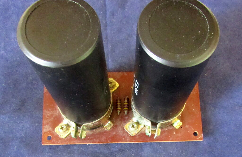
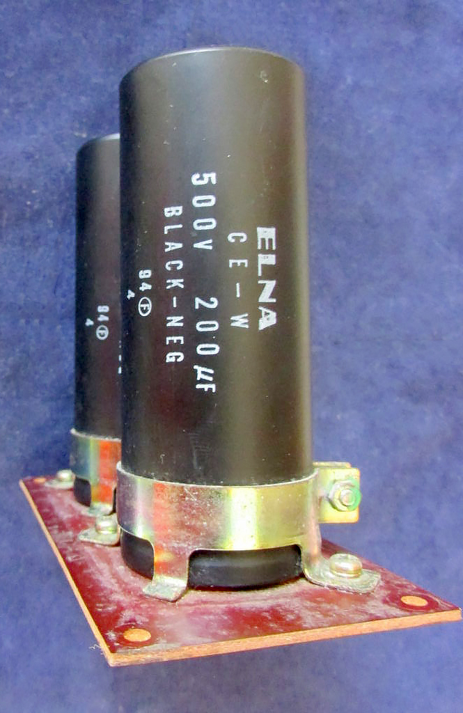
PB-1969A - Filter Capacitor Module
Photo of the PB-1969A Filters Capacitors Module
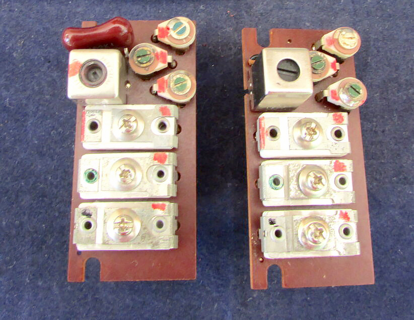
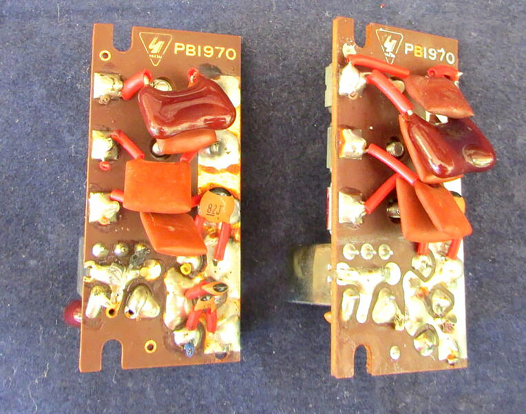
PB-1970 - Trimmer A and B Modules
Photos of PB-1970 Trimmer A and B Modules fitted in all of the Yaesu FT-101ZD's
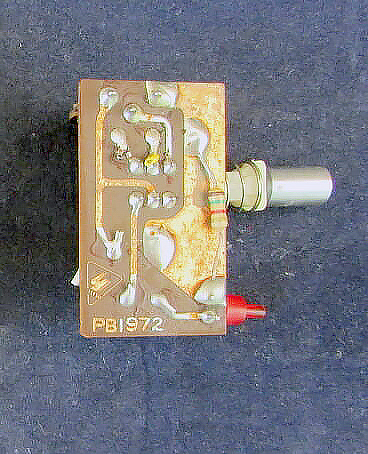
PB-1972 - Single Switch Bandwidth Module
Photo of PB-1972 - Single Switch Bandwidth Module
PB-1973A - Clarifier Module
PB-1974A - LED Module
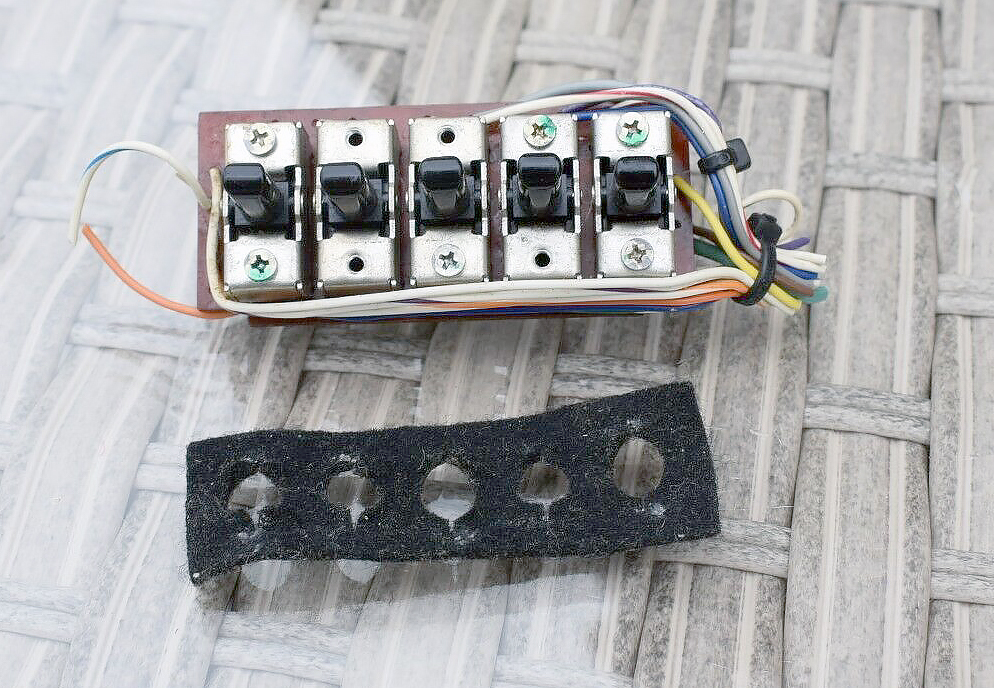
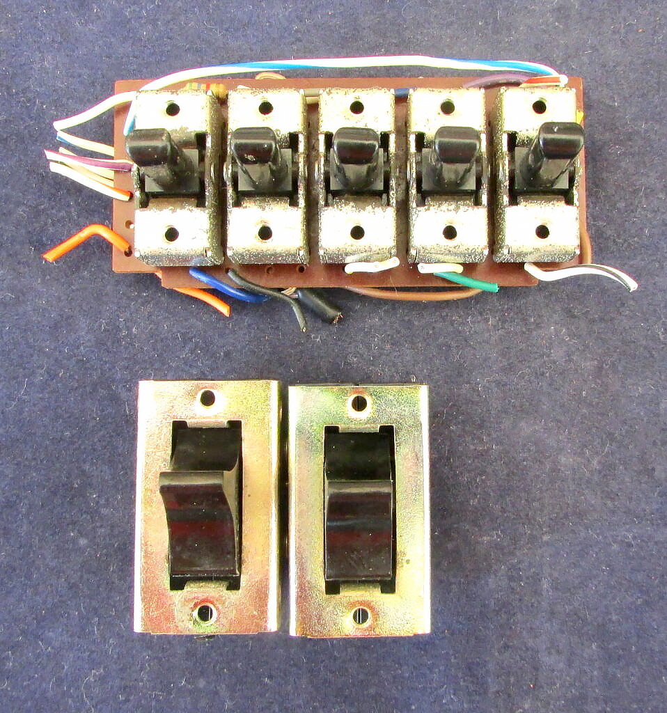
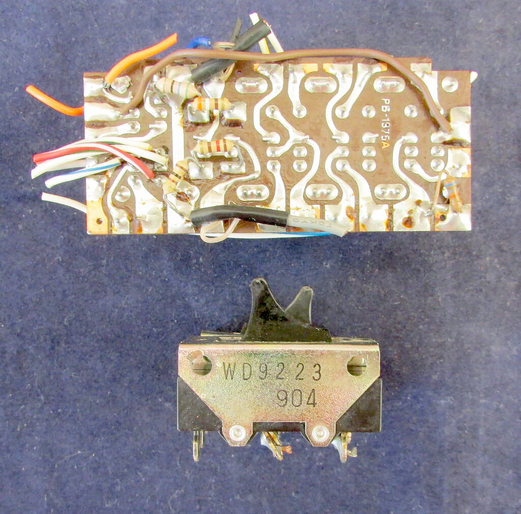
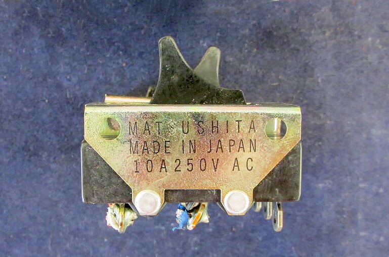
PB-1975A - Lever Switch Module
Photo of the PB-1975A Lever Switch Module used in the ~FT-101ZD Transceiver.
PB-1978 - Display Module
PB-1979 - Decoder Module
PB-1980 - Counter Module
Photo of PB-1980 Counter Module
Used in production runs 01 to 15 in the FT-101ZD.
This counter is a complete enclosed unit consisting of a display board, counter board and a count/decoder board.
The unit uses standard TTL circuits.
The counter has a offset programming to display the correct frequency of the carrier in a ingenious manner.
The counter is programmable for other offsets with dipswitches.
The counter uses 6 HP red displays for a frequency readout to 100 Hz resolution.
This Module is used in the FT-101ZD Mark 0 and Mark 2 up till the end of Production Run 15.
PB-2040 - AM Module
This board is used in the FT-101ZD Mark 1, Mark 2 and Mark 3 models, It was an optional board so it is not used in all transceivers.
PB-2086A - Counter Module
Photo of PB-2086A-3420 Counter Module
This Module is used in the FT-101ZD Mark 1 (Production Run 16 onwards) until the end of the FT-101ZD Mark 3 production.
This Module is used in the FT-101ZD Mark 1 (Production Run 16 onwards) until the end of the FT-101ZD Mark 3 production.
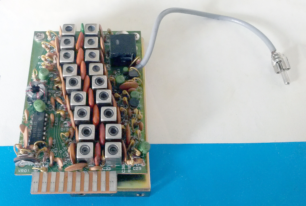
PB-2152 - Pre Mixer Module
Photo of the PB-2152 Pre Mixer Module used in the FT-101ZD Mark 3 transceiver.
The Pre Mixer Module mixes the signal from the Premix Local unit with the VFO or Crystal controlled signal in a double balanced mixer.
The premix signal is passed through a band pass filter and delivered to the RF unit.
This is the newer module which superseded the PB-1962 Module which only had 7 filters, this module has 9 filters for coverage on all amateur bands including the WARC bands..
PB-2152C - Pre Mixer Module
Photo of PB-2152C - Pre Mixer Module
PB-2153 - Band Module
Photo of the PB-2153 Band Module that was only installed in the FT-101ZD Mark 2 and Mark 3 versions.
This is newer plugin board that was only used in the Yaesu FT-101ZD Mark 2 and Mark 3 versions.
It has all the Amateur Bandsincluding the WARC bands 30 Meters, 17 Meters, and 12 Meters.
This board has no ‘WWV” or a optional ‘AUX’ Band.
PB-2154A - Front End RF Module
Photo of PB-2154A Front End RF Module that was used in the FT-101ZD Mark 2 and Mark 3 Models.
Contains the RF pre-amplifier, the receiver and transmitter mixer and a buffer stage, the Mixer output of 8.9875 MHz goes to the IF board.
The In and Output tuning of the RF amplifier is done by permeability-tiuned circuits resulting in high sensitivity and excellent rejection of unwanted out-0of-band signals.
This board uses a diode ring mixer for better big signal behaviour over the previous model (PB-1960A) which used a balanced mixer with 2 FET’s..
This Module is The FT-101ZD Mark 2 and FT-101ZD Mark 3.
PB-2162A - Pre Mixer Module
Photo of the PB-2162A Pre Mixer Module used in the Yaesu FT-101ZD Transceiver.
PB-2192B - Trimmer Module
PB-2193B - Trimmer Module
PB-2217 - APF and Notch Filter Module
The APF Module is switched in the audio circuit by the APF/Notch switch on the front panel.
For APF operation it forms a selective active filter, to narrow the passband of the receiver for a better reception on a crowded band.
The notch function elimenates selective some audio frequencies, like carriers or other interfering signals.
The center frequency of the APF/Notch is adjustable from the front.
This unit is used only in the MK3 model.
PB-2218 - FM Module
PB-2219 - FM Module
This optional board is used for receiving and transmitting in FM mode, the board uses the same connections as the AM Board (PB-2040) which needs to be removed (if installed) when installing this FM Board. Only one board can be installed at any time. Installation is very easy. This board can be installed in production runs from 24 onwards in the Yaesu FT-101ZD Mark 3
Crystals
I have come across some really weird combinations of crystals that have been installed inside the Yaesu FT-101 Series of transceivers, understandably the Yaesu FT-101ZD has been the biggest culprit of weirdness that you come across.
All of the Crystals used in these transceivers are of the type ‘HC-25/U‘, these are a very common type and easily available.
Below is a listing of Crystals for the series and my understandings as to what they are used for.
The Maths behind Crystal Selection.
There is a very simple way to work out what frequency Crystals are required to be installed into the Yaesu FT-101 Series of Transceiver.
The formula is:
Fx = (F1 + Fc) – Fo
Fx is the Crystal Frequency Required to be installed into the FTY-101 Transceiver.
Fo is the Desired Operating Frequency.
(F1 + Fc) is the Frequency Constant, this can be taken from the table below.
Band
LSB
USB
AM/CW
160 Meters
10701.5 KHz
10698.5 KHz
10.699.3 KHz
80 Meters
12701.5 KHz
12698.5 KHz
12699.3 KHz
40 Meters
16201.5 KHz
16198.5 KHz
16199.5 KHz
20 Meters
23201.5 KHz
23198.5 KHz
23199.3 KHz
15 Meters
30201.5 KHz
30198.5 KHz
30199.3 KHz
10 Meters (A)
37201.5 KHz
37198.5 KHz
37199.3 KHz
10 Meters (B)
37701.5 KHz
37698.5 KHz
37199.3 KHz
10 Meters (C)
38201.5 KHz
38198.5 KHz
38199.3 KHz
10 Meters (D)
38701.5 KHz
38698.5 KHz
38699.3 KHz
So if you wish to operate on 3900 KHz (or 3.90 MHz) LSB on the 80 Meter Band, the working out would be as follows:
From the Table above we can that the Frequency Constant (F1 + Fc) is 12701.5 KHz.
So all we need to do is work out the Fx, this is simply by taking our valve for (F1+Fc) which is 12701.5 KHz and then subtracting this from Fo, which is 3900 KHz, i.e. 12701.5 – 3900 which gives us our value for Fx: 8801.5 KHz
So the Crystal required to be installed into the 80 Meter section of the Yaesu FT-101 would be 8801.5 KHz or 8.8015 MHz.
Below are a list of the Crystals that I have come across and the frequencies that they give you when installed into the sections that I have found them, this will show you what is standard and what is often not standard and better referred to as ‘Bodged’ by so called ‘Rig-Doctor’s’ back in the days of the CB Hackers.
One of the first ways to check how ‘un-touched’ your new find is, is to check the crystals that have been installed, if they are standard, then there is a good chance that the ‘Trimmers’ in the radio have not been played with as well, as quite often these ‘Rig Doctors’ often would try and tune the radio for set frequencies, the most common being the 11 Meter band for use on the CB frequencies.
More often than not, these have not been set-up correctly and you will be looking at doing a proper realignment to the set.
160 Meters
15.9875 MHz
80 Meters
9.520 MHz
17.9875 MHz
40 Meters
21.4875 MHz
30 Meters
24.4875 MHz
20 Meters
20.020 MHz
28.4875 MHz
17 Meters
32.4875 MHz
15 Meters
Bank ‘X4’
24.020 MHz
If this Crystal is found in this location (X4), this normally shows that someone has modified the radio for use on the WARC Bands, InRAD was one of the few companies that supplied kits for this modification, it also means that TC-19 (15 Meters) and TC-20 (11 Meters)Trimmers have been adjusted. This Crystal should have been removed from this location as the standard 27.020 MHz Crystal is actually used for the WARC modification, So finding this Crystal in this location in your radio means that not only was it played with, but also as it was left, it was played with by someone who cannot read instructions.
Correct Value for X4
27.020 MHz
35.4475 MHz
12 Meters
33.9875 MHz
38.9875 MHz
11 Meters
Bank ‘X5’
30.520 MHz
If this Crystal is found in this location (X5), this normally shows that someone has modified the radio for use on the WARC Bands, InRAD was one of the few companies that supplied kits for this modification, it also means that TC-19 (15 Meters) and TC-20 (11 Meters)Trimmers have been adjusted. This Crystal should have been removed from this location as the standard 27.020 MHz Crystal is actually used for the WARC modification, So finding this Crystal in this location in your radio means that not only was it played with, but also as it was left, it was played with by someone who cannot read instructions.
32.020 MHz
26.0 to 26.5 MHz
32.520 MHz
26.5 to 27.0 MHz
Correct Value for X5
33.020 MHz
27.0 to 27.5 MHz
33.520 MHz
27.5 to 28.0 MHz
41.4875 MHz
27.0 to 27.5 MHz MHz
41.9875 MHz
27.5 to 28.0 MHz MHz
10 Meters
Bank A
34.020 MHz
42.4875 MHz
Bank B
34.520 MHz
42.9875 MHz
Bank C
35.020 MHz
43.4875 MHz
Bank D
35.520 MHz
43.9875 MHz
Filters
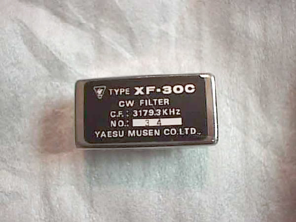
On the Low Frequency IF Module you will often find the XF-30A or XF-32A SSB filters, XF-30C 600 Hz CW filter or the XF-30B 6 KHz wide AM filter.
Yaesu XF-30C - 600 Hz CW Filter
Yaesu XF-30C 600 Hz CW Filter for the Yaesu FT-101 Transceiver
Center Freq 3179.3 KHz
Yaesu XF-30C - 600 Hz CW Filter
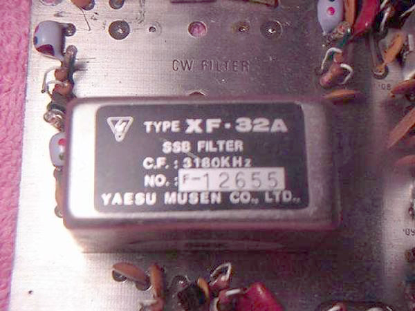
Yaesu XF-32A 2.4 KHz SSB 8 Pole Filter
Center Frequency 3180 KHz
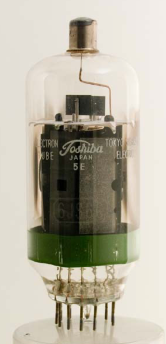
6JS6C Tubes
The 6JS6C vacuum tube is a TV Deflection Tube, or “Sweep Tube”.
Although not meant for transmitting, it exhibits sufficient performance for RF operation through 30 MHz.
There will come a time when the finals in your FT101E will need replacing.
The FT-101 transceivers were originally equipped with 6JS6C tubes manufactured by NEC and Toshiba.
Other manufacturers tube properties are slightly different from the original 6JS6C tubes.
Therefore, a simple modification to the neutralization circuit must be made to the final section of the transceiver.
The modification consists of replacing the fixed value 100 pf 1000 VDC mica capacitor with a 10 pf 1000 VDC mica capacitor.
This capacitor, C125, is in series with the 10 pf variable neutralizing capacitor off of the plate circuit.
If this modification has not already been completed on your radio, be sure to use a mica or silver mica of at least 1000 VDC.
Do not substitute a different type because the heat in the final compartment will change the value, and your tubes will fail prematurely.
Also, be very careful to keep all leads short and in exactly the same orientation as the original capacitor.
6JS6C Vacuum Tube
Power Amplifier (Tank) Circuit
Before re-neutralizing, open the variable neutralizing capacitor all the way to minimum engagement and follow the neutralizing instructions in the manual.
While dipping the PLATE, remember to adjust the neutralizing capacitor for equal value meter reading “dips” (Ic meter position) on both sides of the peak when tuning the PLATE control.
WARNING! You are tuning a capacitor in the High Voltage compartment, +600 Volts are present!
Always use non-metallic tuning tools.
After neutralization, reset the bias to 60ma with CARRIER and MIC settings at minimum.
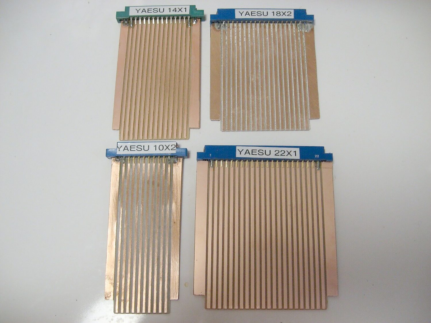
Extender Boards
Yaesu FT-101 - Extender Boards, A Must for working on these old units.