Elecraft K3 - Another New Toy
As you can imagine, I have had it in the neck for getting this one, “Have you not got enough radios by now”, but they do not see the difference between old radios that are not working and waiting to b restored, and the two that I have got lately.
Not long ago, and very much while I was basically dying in Hospital and generally feeling crap, I managed to purchase another radio that I had always wanted, the Yaesu FT-2000, thank to a good friend.
Now I am sure it is a great radio, but not when you are drugged up on horse tranquilisers and find it hard to even remember your own date of birth, but I know it is a great radio, and I know that it will operate really well, but, my head was having a problem with the menu and with trying to work out why I could not turn off transmit when I used the Morse yet, I know, simple stuff, but feeling crap from way too many drugs made it pretty difficult to get my head round, so – there was nothing else for it than to buy another good radio.
I suppose deep down I was in two minds, I have always loved Icom’s and so the IC-7610 would be the favorite option, and on the other side was the Yaesu FTDX-5000 (Late Model Version), and I know, it’s basically the same as the FT-2000 but with better filtering, but again it has been on the wish list and not owning a radio since 2014 has left me wanting something good.
Thankfully someone that I had kind of walked away from after something happened had reached out to me while I was in Clatterbridge and certainly not in a good way, Now I would have said that in the past Godfrey (GD4EIP) was certainly a dam good friend, if not a best friend, but we had a small disagreement and I walked away.
Over the years that passed, he also had some battles to fight with illness and very sadly e lost his wife not too long ago, anyway e-mail have slowly increased between us and we are talking again, anyway, long story short, he had a K3 for sale and I had always wanted one, but the cost of these units was always more than I could afford.
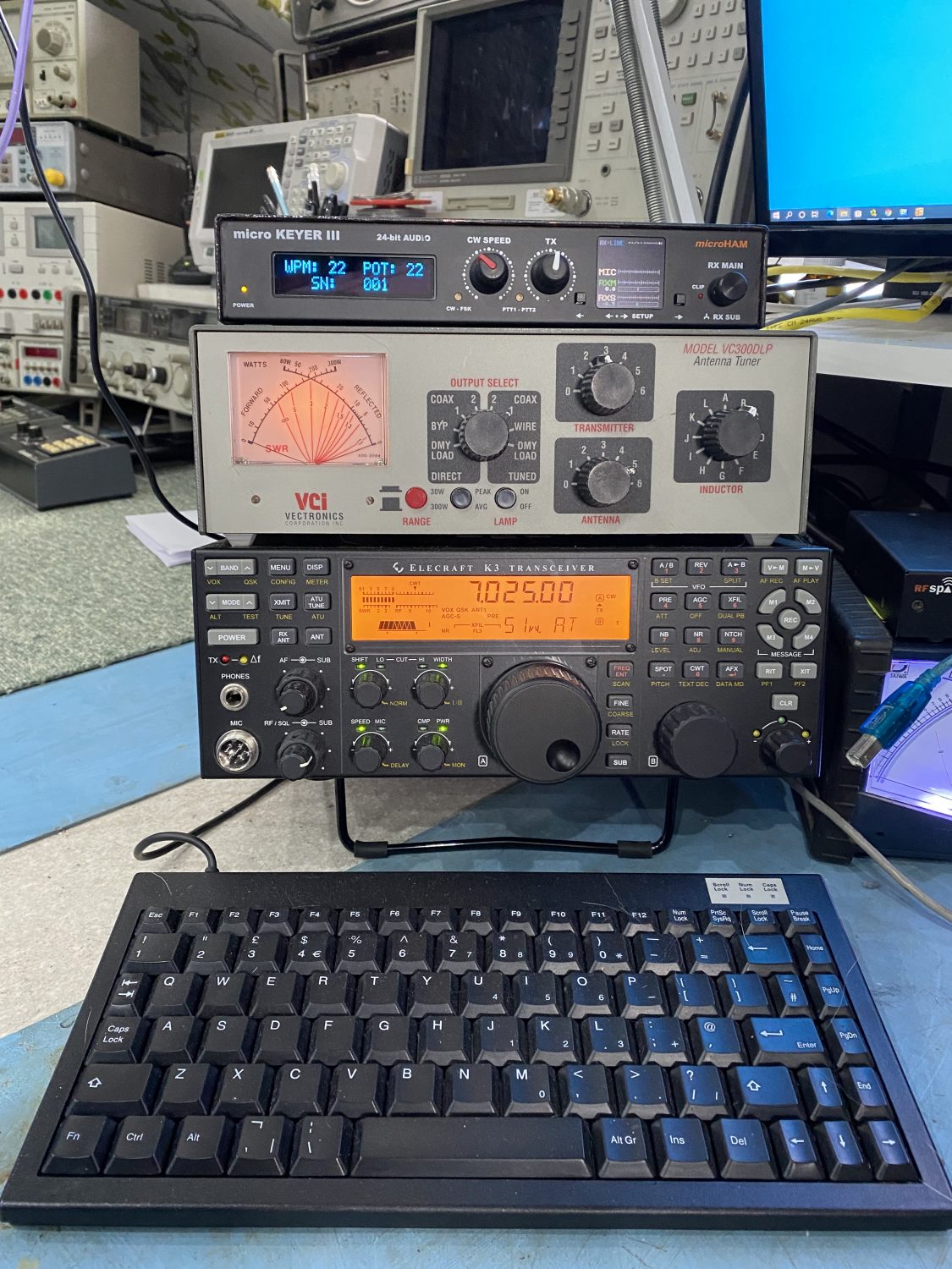
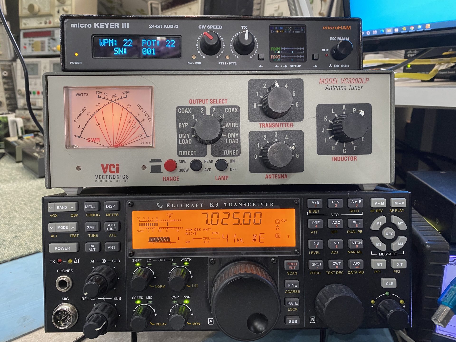
Please excuse the temp set-up.
It’s in the ‘workshop’ and there should be no radios in this room!
So after biting his hand off, I am the proud owner of a radio that I have only ever used back when the good friends from Germany visiting, or from when I was taken to Germany by Mike, also quite a few years back.
It's not that different - But WOW!
I have had some very nice ‘Hand Me Downs’ over the years, and one of my favourite transceiver was the original Ten Tec Orion that I was very kindly given by a good friend of mine, Douglas (GD3RFK)
Sadly for me it had gone through the wars since I have taken over the care of this radio, I lost the display one day and it would not come on for some reason, nut a quick hunt through the forums came up with adding a small spacer to the screws holding the display to the front of the radio, this sorted out this problem.
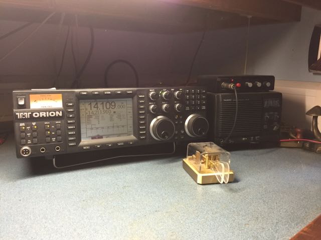
The final sage for this radio is that the Power Supply board failed twice over three months, first time was a known issue of bad capacitors which I replaced and upgraded at the same time, the second was rather dramatic, with a few load bands and a good sized fizzle.
I decided this time it would have to go away and could not find anyone interested in repairing it here in the UK so off she went to the USA and about 3 months later she returned all singing and dancing again.
That was many years ago and she has been in storage ever since due to the water leak in the house which this radio was thankfully not in the old workshop at the time.
If anyone has a Internal ATU for this model please contact me as I would be very interested.
My reason for bringing up the TenTec was that it was such a ghreat radio to use and the noise reductions was just fantastic, and I love it, yes it went wrong a few times but what do you expect, if it was that good then Ten Tec would still be around.
Anyway previous to this I was really happy with Icom and my beloved IC-775DSP which for me was one of the best radios that I have come across, I have used the modern transceivers from Icom such as the IC-7610 and the IC-7800 and they are really good, and I would get one if I could afford it, but funds are very low, I have been very ill and still am and will be for some time to come.
I am not proud to say that I have heavily relied of some very good friends here. Their kindness will never be forgotten.
Anyway, the Elecraft was always a Dream Radio, if you check out the Rob Sherwood page you should understand why, it has only recently been pushed down to the 5th spot by the likes of the Yaesu FTdx-101D.
The Specifications of my Elecraft K3 are:
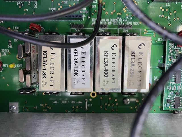
Filters Fitted:
- 2.7 KHz
- 1.8 KHz
- 1 KHz
- 400 Hz
- 250 Hz
Modules Fitted are:
- KXV3 Interface
- KSYN3A Synthesizer
- KPA3 100W Amplifier
- KAT3A Automatic Antenna Tuner
OK, it has a Menu, and Multifunction buttons, but it is still very easy to use, and it does feel like you have come home.
The Noise reduction is just beautiful, the one I have is fully filtered and you really do notice the difference.
Below you will find the ‘Menu’ settings that I have on the K3 that I have here.
Main Menu Settings
It is always best to make a record of the settings on the radio when you first switch it on, this way you can see the items that have been changed from default, it makes it easier to just see which items have been changed and then see if there was a reson that makes sence.
| Main Menu Item | My Radio | Default | Description |
|---|---|---|---|
| AFX MD | Delay 5 | Delay 5 | Audio Effects. Selections: DELAY 1-5 (quasi-stereo); BIN (L/R phase shift) |
| ALARM | OFF | OFF | Set alarm/Auto-Power-On time. Tap 1 to turn alarm on/off; tap 2 / 3 to set HH/MM. |
| ATTEN | 10 dB | ||
| LCD ADJ | 13 | 8 | LCD viewing angle and contrast. Use higher settings if the radio is used at or above eye level. If adjusted incorrectly, bar graphs will be too light or heavy during keying. |
| LCD BRT | 4 | 6 | LCD backlight brightness. Use DAY in bright sunlight, 2 to 8 for indoor lighting. |
| LED BRT | 4 | 4 | LED brightness (relative to LCD backlight brightness). Exception: if LCD BRT is set to DAY, LEDs are set to their maximum brightness. |
| MIC SEL | FP.H Bias | FP.L Bias Off | Mic/line transmit audio source, mic gain range, and mic bias. Source selections: FP (front panel 8-pin MIC jack), RP (rear panel 3.5 mm MIC jack), and LINE IN (rear-panel LINE IN jack). Tap 1 to toggle between .Low and .High mic gain range for the selected mic. Tap 2 to turn mic BIAS on/off (turn on for electret mics). For the front-panel mic only, tap 3 to turn on an additional gain stage. Use this only with very low-output mics. An apostrophe will appear after the H, e.g. H’ . |
| MIC+LIN | OFF | OFF | If set to ON, and MIC SEL is set for FP or RP, the present mic OR line input can be used for transmit audio. NOTE: Setting MIC SEL to LINE overrides the MIC+LIN menu entry (its parameter becomes “N-A”). When MIC+LIN is in effect, rotating the MIC control shows MIC gain. The op has to set MIC SEL to LINE temporarily to adjust LINE IN gain. |
| MSG RPT | 6 | 6 | Message repeat interval in seconds (0 to 255). To repeat a message, hold M1 – M4 rather than tap. A 6 – 10 sec. interval is about right for casual CQing. Shorter intervals may be needed during contests, and longer for periodic CW beacons. |
| RPT OFS | 600 | 600 | Sets the transmit offset (in kHz) for repeater operation, from 0 to 5000 kHz. Store per-band and per-memory. Use ALT to select a +/- offset or simplex operation. |
| RX EQ | 0 dB for All Bands | 0 dB for All Bands | Receiver audio graphic equalizer. VFO A is used as an 8-band bar graph, showing boost or cut ( -16 dB to +16 dB in 1 dB increments) for each AF band. The 8 bands are 0.05, 0.1, 0.2, 0.4, 0.8, 1.6, 2.4 and 3.2 kHz. Tap 1 -8 to select an AF band. VFO A selects boost/cut. Tap CLR to reset all bands to +0 dB. CW RX EQ is separate from RX EQ for voice modes. Not applicable to DATA |
| TX EQ | 0 dB for All Bands | 0 dB for All Bands | Transmit audio graphic equalizer (voice modes only). Functions the same as RX EQ, above. TX EQ can be adjusted during transmit. SSB TX EQ is separate from TX EQ for other voice modes. Not applicable to CW or DATA modes. |
| VOX GN | 0 | 0 | Adjusts the sensitivity of the VOX to match your mic and voice. |
| ANTIVOX | 0 | 0 | Adjusts immunity of the VOX circuit to false triggering by speaker audio. |
Config Menu Settings
And again make a not of the settings before you change them.
| Config Menu Item | My Radio | Default | Description |
|---|---|---|---|
| 2 TONE | OFF | OFF | (Troubleshooting.) Enables built-in 2-tone generator for SSB transmit tests. The internal 2-tone generator only works if LSB or USB mode is selected. After setting 2-tone ON, exit the menu and tap XMIT. You can use MIC to adjust the amplitude of one of the tones; the other’s amplitude is fixed. |
| ADC REF | 5.00 | 5.00 | Allows calibration of the voltage reference used by the K3 to measure and display certain values, such as the rig’s supply voltage. (Optional.) First, disconnect anything attached to the ACC jack. Next, locate the ADC REF menu entry. It will initially show 5.00 volts as the reference voltage. Using a DMM set to DC volts, measure the actual voltage at pin 2 of the ACC jack. This must be done while the ADC REF parameter is being displayed. (Note: The (-) probe of the DMM should go to the K3’s chassis ground, e.g. at the GROUND lug.) Finally, use VFO A to set the ADC REF menu parameter to what you measured at pin 2. |
| AF GAIN | HI | HI | Sets AF gain range. Available selections are HI or LO. |
| AF LIM | NOR | NOR | (Advanced.) Adjustable AF output limiter for use when AGC is turned off. This can protect your ears if a large signal appears. Signals or noise above the threshold will sound highly distorted due to the limiting action, reminding you to back down the AF or RF gain. Typical settings for those who often turn AGC off are 17 to 23; some experimentation will be required. |
| AFSK TX | FIL OFF | FIL OFF | If set to FIL ON, a 400-Hz transmit audio filter is added (via DSP) in order to maximize transmit signal to noise ratio. This may be useful in high-noise computer environments. Applies only to AFSK-A mode (RTTY). |
| AFV TIM | – – | 1000 | (Advanced.) Integration time for AFV and dBV displays in ms. See VFO B alternate display information. |
| AGC DCY | SOFT | NOR | AGC decay characteristic; applies to both fast and slow AGC. NOR selects traditional linear decay. The SOFT setting can reduce IMD caused by traditional AGC, and is especially useful in “pileup” conditions, in some cases making it unnecessary to turn AGC off. Also see AGC HLD, below, which can reduce AGC IMD even further. |
| AGC HLD | 0.00 | 0.00 | SLOW AGC “hold” time. Specifies the number of seconds that the SLOW AGC level is held after the signal drops. This can be used to reduce IMD caused by traditional AGC, and is especially useful in “pileup” conditions, in some cases making it unnecessary to turn AGC off. |
| AGC PLS | NOR | NOR | (Advanced.) NOR enables AGC noise pulse rejection. |
| AGC SLP | 007 | 012 | (Advanced.) Higher values result in ‘flatter’ AGC (making signals at all amplitudes closer in AF output level). |
| AGC THR | 012 | 005 | (Advanced.) Sets AGC onset point; a higher number moves the onset up. |
| AGC F | 120 | 120 | (Advanced.) Sets fast AGC decay rate; a higher number means faster decay. |
| AGC S | 20 | 20 | (Advanced.) Sets slow AGC decay rate; a higher number means faster decay. |
| AUTOINF | NOR | NOR | (Advanced.) If set to AUTO 1, the K3 will send band data on its RS232 port for use with devices such as the SteppIR™ antenna on every band change. (Note: This setting may not be compatible with PC software applications that use the “AI” remote control command.) |
| BAT MIN | 11.0 | 11.0 | Low-battery warning threshold; 11.0 recommended. (This refers to a battery used as the K3’s DC power supply, not to the 3-V backup battery for the real-time clock.) If the voltage drops below this level, the operator will be alerted with a BAT LOW message. The menu parameter flashes if this occurs within the menu, so the level can be easily tested. |
| BND MAP | (band) In | (band) In | Allows you to remove one or more bands from the BAND rotation. Use BAND up/down to select bands, then set them to In or Out using VFO A. (Works with transverter bands, too.) You can still get to mapped-out bands using memory recall, direct frequency entry, or computer-control commands. |
| CW IAMB | B | A | Iambic keying mode (A or B). Both modes produce self-completing dots and dashes. Mode B is more efficient for operators who use “squeeze” keying (pressing both paddles at once), because an extra dot or dash is inserted on squeeze release. Mode A lacks this feature, which may be more appropriate for those who only press one paddle at a time (often called “slap” keying). |
| CW PADL | TIP=DOT | TIP=DOT | Specifies whether left keyer paddle (“tip” contact on the plug) is DOT or DASH. |
| CW QRQ | OFF | OFF | (Advanced) Set to ON to provide CW keying speeds of up to 100 WPM and much faster break-in at all speeds. The internal keyer range becomes 8-100 WPM in this case. Caution: In QRQ mode, the delay from key down to first RF out may be as little as 4 to 5 milliseconds. This may be too fast for some external amplifiers. You may be able to slightly increase the CONFIG:TX DLY setting to compensate, but you should then listen to your signal on another receiver to ensure that your CW keying doesn’t exhibit excessive jitter (perelement variation). This is more likely to occur with external keyers. Note: If you use SPLIT, RIT, XIT, or cross-mode, QRQ mode will be temporarily turned off. Filter passband SHIFT/LOCUT/HICUT cannot be used when CW QRQ is in effect. |
| CW WGHT | 1.10 | 1.15 | Adjusts element/space timing ratio (weight) for the internal keyer. Additional functions of this menu entry, via numeric keypad (Advanced): Tap 1 to select SSB -CW (default) or SSB +CW (allows CW in SSB modes). Tap 2 to select @ = STOP (‘@’ character terminates KY-packet transmission; default) or @ = ‘AC’ (‘@’ in a KY packet is sent as .–.-. [@] in CW mode). Tap 3 to select OLD or NEW QSK (default). NEW reduces AF keying artifacts. Tap 4 to select VOX NOR (default) or AUTO OFF. The AUTO OFF setting turns CW VOX off on power-up, avoiding accidental keying by attached PCs, etc. Tap 5 to select automatic VFO offset on SSB/CW mode change (VFO OFS) or no offset (VFO NOR, default). Automatic offset is often used on 6 meters, where mixed-mode QSOs are necessary during fading. Note: Pitch matching will be more accurate if USB is paired with CW REV, and LSB with CW normal. |
| DATE | n/a | n/a | Real-time-clock date, shown as in the format selected by CONFIG:DATE MD (MM.DD.YY or DD.MM.YY). Tap 1 / 2 / 3 to select month / day / year. |
| DATE MD | EU | US | Select US (MM.DD.YY) or EU (DD.MM.YY) date formats. |
| DDS FRQ | – – | – – | (Troubleshooting.) Controls DDS tuning directly to check DDS XFIL range for synthesizer troubleshooting purposes. Rotate VFO A CCW and CW to find limits where L (lock) changes to U (unlock). Correct DDS frequency is restored after exiting the menu and rotating either VFO. |
| DIGOUT1 | OFF | OFF | DIGOUT1 is a general-purpose open-drain output signal on the ACC connector (pin 11). OFF = floating; ON = pull the line to ground. DIGOUT1 is per-band, and also per-antenna if the KAT3 ATU is installed. It can be used to turn an Elecraft PR6 preamp on when you switch to 6 meters, control a remote antenna switch, etc. Max. load current (ON) is 15 mA; max. load voltage (OFF) is 25 VDC. |
| DUAL PB | APF | APF | Assigns one of two specialized filter functions to the DUAL PB switch in CW mode: APF (audio peaking filter) or NOR (Dual-Passband Filtering, or Dual PB). See pg. 35 for details on the two functions. |
| EXT ALC | OFF T-40 | OFF T-40 | (Advanced) Set to ON only if using external ALC with a high-power amplifier. This may require modifications to your K3’s RF and KIO3 modules (see pg. 27 for details). When set ON, the K3’s external ALC threshold (-4.0 V by default) can be varied. |
| FL3 BW | 1.00 | – – | Crystal filter FL1-5 bandwidth in kHz, where x=1 to 5 (FL1-FL5). Tap 1 -5 to select a specific filter, or tap XFIL (6 ) to select the next filter. Then set the bandwidth to that marked on the crystal filter. (If desired, the value entered can be slightly different from the marked value. For example, you might set the bandwidth of the 8-pole, 400-Hz filter to 0.45 kHz rather than 0.40 kHz. This delays automatic filter switching by the WIDTH control to 0.45, which may be advantageous if you believe the 400-Hz filter still performs well at 450 Hz.) |
| FL3 FRQ | 0.00 | – – | Crystal filter FLx center freq as offset from nominal (8215.0 kHz). Use the offset value specified on the crystal filter’s label or PC board, if any. For example, if an Elecraft 5-pole, 200-Hz filter were labelled “-0.91”, adjust VFO A for –0.91. |
| FL3 GN | 0 dB | – – | Crystal filter FLx loss compensation in dB. 0 dB recommended for wide filters; 2 dB for 400 or 500 Hz filters, and 4 dB for 200 or 250 Hz filters. |
| FL3 ON | YES | – – | Used to specify which filters are available during receive. Each filter must be set to ON or OFF in each mode. You can tap MODE within the menu entry. |
| FLTX | FL1 | – – | Used to specify which crystal filter to use during TX. {md} = CW/SB/AM/FM. Choose filters with bandwidths as follows: SSB, 2.7 or 2.8 kHz (also applies to data); CW, 2.7 or 2.8 kHz; AM, 6 kHz; FM, 12 kHz or higher. The FM filter, if present, must be installed in FL1. Note: If you’re using a 2.7-kHz 5-pole filter for SSB transmit, you can optionally fine-tune its FLx FRQ parameter to equalize LSB / USB transmit characteristics. Monitor your signal on a separate receiver, using headphones |
| FM DEV | 5.0 | 5.0 | (Advanced) FM voice deviation in kHz. Tap 1 to change the function to PL DEV (PL tone deviation). Note: The deviation setting for sub-audible tones (CTCSS) is separate from that for the European standard tone (1750 Hz). Before adjusting PL DEV, select the desired pitch with the PITCH switch. |
| FM MODE | ON | ON | If set to OFF, FM will be removed from the mode selections. |
| FP TEMP | 35C | n/a | If set to OFF, FM will be removed from the mode selections. |
| FSK POL | 0 | 1 | 0 = Inverted FSK transmit data polarity, 1 = Normal data polarity. For use only with external FSK-D keying via programs such as MMTTY. Not recommended for CW-to-DATA use. |
| FW REVS | 05.67 | n/a | Rotate VFO A to see firmware revisions: MCU (uC), main DSP (d1), aux DSP (d2, if KRX3 is present), flash parameters (FL), and KDVR3 controller (dr ). |
| KAT3 | AUTO | NOT INST | KAT3 ATU mode; normally set to BYP or AUTO (outside the menu, ATU alternates between the two). Modes L1-L8, C1-C8, and Ct are used to test KAT3 relays. Mode LCSET allows manual adjustment of L/C/net settings (you must exit the menu first). When in LCSET mode, tapping ATU TUNE shows the L and C values; C is changed with VFO A, L is changed with VFO B, and ANT toggles between Ca and Ct . |
| KBPF3 | NOT INST | NOT INST | If KBPF3 option is installed: set to NOR, exit menu, and turn power off/on. |
| KDVR3 | NOT INST | NOT INST | If KDVR3 option is installed: set to NOR, exit menu, and turn power off/on. Note: Normally, playing DVR transmit messages automatically asserts PTT. To use manual PTT with DVR transmit (via a footswitch or external sequencing equipment), tap 1 within the KDVR3 menu entry until you see USE PTT. |
| KIO3 | NOR | NOR | Determines function of BAND0-3 outputs on ACC connector. |
| KPA3 | PA NOR | NOT INST | Set to PA NOR if KPA3 100-W amp installed. Set to PAIO ON if KPA3 is not installed, but the KPAIO3 transition PC board is. Other settings include PA BYP (disables KPA3 if installed), PA fan test settings (PA FN1-FN4 or PAIO FN1- FN4), and PAIO BYP (if transition board is installed, but not the KPA3 module, this setting can be used to test the high power bypass relay). |
| KRC2 | – – | – – | Controls the KRC2 band decoder’s accessory output settings. Shows ACC OFF or ACC1-3 if a KRC2 is detected; – – if not. To ensure compatibility with both old and new KRC2 firmware, two different 6 meter band decodes are provided. Tap 1 to select BAND6=B6 (addr=10) or BAND6=B10 (addr=9). Refer to the KRC2 manual for further details. |
| KRX3 | NOT INST | NOT INST | If KRX3 option (sub receiver) is installed, set the parameter to match your selected sub receiver AUX RF source: ANT=ATU (the KAT3’s non-transmit antenna) or ANT=BNC (the AUX RF BNC jack on the rear panel). Turn power off, then back on. |
| KXV3B | NOR | NOT INST | If KXV3 or KXV3A option is installed: set to NOR, exit menu, and turn power off/on. This option provides RX ANT IN/OUT jacks, low-level transverter I/O (XVTR IN/OUT), and a buffered I.F. output. The updated KXV3A supports the internal 2-m module (K144XV). If KXV3 is set to TEST, the K3 will use low power (0.10 to 1.50 mW) on all bands, including HF and transverter bands. RF input/output is via the XVTR IN/OUT jacks in this case. Used for troubleshooting. Note: To access the TEST setting, KXV3 must first be set to NOR, then K3 power turned off/on. |
| LCD TST | OFF | OFF | Rotating VFO A to turn on all LCD segments for test purposes. |
| LIN OUT | NOR 010 | NOR 010 | Sets the LINE OUT level. LINE OUT connections go to PC soundcard inputs. Settings above 10 may result in overdrive of the soundcard or saturation of the KIO3’s isolation transformers; monitor signals using the PC to avoid this. Note: Normally, LIN OUT sets a fixed-level receive-only output for main/sub (L/R), compatible with digital modes. Tapping 1 switches LIN OUT to =PHONES, where the line outputs match headphone audio, audio level is controlled by AF/SUB gain controls, and both RX and TX audio are available. |
| MACRO 1 | FUNCTION | FUNCTION | Used to assign macros (sequences of remote-control commands) to any of the K3’s programmable function switches. For example, a single macro can do the equivalent of “SPLIT, up 2 kHz, turn on diversity mode”; setup transmit EQ for a specific operator; configure the K3 for a contest, etc. Macros must first be created using K3 Utility and sent to the K3. Next, locate the MACRO x menu entry, tap 1 -8 to select a macro number (x), then hold the desired programmable switch (e.g. PF1 ) to assign that macro to it. For details, see K3 Utility help or the K3 Programmer’s Reference. |
| MEM 0-9 | NOR | NOR | If the parameter is set to BAND SEL, frequency memories 0-9 (“quick memories”) will act like band switches. Once this mode has been selected, exit the menu, then use V M to assign individual bands to keypad switches 0-9. For example, use BAND to get to 160 m, tap V M, then tap #1 . From then on, tapping M V , then #1 , will take you to your last-used frequency on 160 m, just as if you had used the BAND switch. This menu entry also controls the behavior of memory recall (M V ) when selecting memories 00-99 using VFO A: Normally, when you tap M V , rotating VFO A through memories 00-99 switches the receiver to the indicated frequency as soon as the VFO stops moving. You can change this behavior by tapping 1 in the MEM 0-9 menu entry. This alternates between M>V NOR (“live” memory recall) and M>V DLY (“delayed”). In the latter case, the receiver will not switch to new frequencies until you tap M V to return to normal operation. |
| MIC BTN | OFF | OFF | Set to ON if your mic has UP/DOWN buttons compatible with the K3’s frontpanel mic jack. Not applicable to the Elecraft MH2 or MD2 microphones. Tapping UP/DOWN once moves the VFO up/down one step (based on current tuning rate); holding UP/DOWN moves up/down continuously. If frequency moves up/down continuously, your mic is not compatible; set MIC BTN OFF. |
| L-MIX-R | A B | A B | Sets left/right mix of main (A) and sub (B) audio. Default is main full left, sub full right. A setting of AB B would provide main/sub mixing on the left, etc. |
| NB SAVE | NO | NO | Set to YES to save noise blanker on/off state per-band. Noise blanker levels, both DSP and I.F., are always saved per-band regardless of this setting. |
| PA TEMP | 31C | n/a | If a KPA3 (100-W PA module) is installed, shows KPA3 heat sink temperature and allows it to be adjusted. See calibration procedure on pg. 51. If you’re operating at high power from a battery, and voltage is dropping enough to cause an erroneous HI TEMP indication, tap 1 in this menu entry to select R ONLY (receive only) temperature sensing, rather than the default (T AND R). |
| PB CTRL | SHIFT=.05 | SHIFT=.05 | (Advanced) Specifies the granularity of the passband SHIFT control on a permode basis: .05 (default) or .01 kHz. Select the desired mode first, then select the desired granularity. Limitations: Only applies to CW and DATA modes. Selecting .01 kHz reduces the SHIFT range and disables HI CUT and LO CUT. May interfere with spurious signal removal (CONFIG:SIG RMV), i.e. “removed” signals may not be shifted the right amount, and thus may again be audible. |
| PREAMP 2 | OFF | ||
| PTT KEY | OFF-OFF | OFF-OFF | (Advanced) Allows selection of RTS or DTR RS232 lines to activate PTT or key the K3. (See pg. 18 for connections.) Example: if the parameter is set to RTS-DTR, then the RTS line will activate PTT, and DTS will key the rig. Note: If a computer or other device asserts RTS or DTR while you’re in this menu entry, the K3 will switch to TEST mode (zero output) as a precaution. The TX icon will flash as a reminder. To avoid this, make sure software has flow control and/or keying options turned OFF while you’re changing the PTT-KEY selection |
| PTT RLS | 020 | 020 | (Advanced) Provides a delay between release of PTT and dropping of the transmit carrier; intended for use with fast turn-around data protocols such as AMTOR and PacTOR. (No effect in CW, FSK D, or PSK D modes.) A value of 20 or higher may be needed to ensure accurate data transmission with these protocols. If sync data or –S is in effect (see SYNC DT), a lower value, typically 10 to 12, is optimal. Also see AMTOR/PacTOR. |
| PWR SET | NOR | NOR | If set to NOR, the power level on each band follows the present setting of the PWR control. If set to PER-BAND, the power level is saved on each band. This is especially useful with external amplifiers (see ALC discussion on page 75.) If a KPA500 is connected to the K3 via the ACC cable, two sets of per-band power settings are saved: one for “barefoot” operation, one for use with the amp. When the amp is used, an asterisk appears as PWR is rotated (e.g. 30 W* ). Tap 1 to LOCK or UNLOCK the MIC, CMP, and PWR controls. |
| REF CAL | 49.380.00 | 49.380.00 | Used to calibrate the K3’s reference oscillator. VFO A is used to set the reference oscillator frequency in Hz. Typically it will be 49380.000 +/- 1000 Hz. Refer to page 50 for manual reference oscillator calibration details. If a K3EXREF option is installed and connected to an external 10-MHz reference, the REF CAL parameter will be calibrated automatically about 10-15 seconds after power-up. An asterisk will appear in the menu entry name (e.g. REF*CAL); the asterisk flashes as long as data is being received from the K3EXREF. Tapping 1 saves the automatically derived value as the default (manual) value. This is not required, but is useful if the external reference is ever disconnected. |
| RFI DET | NOR | NOR | NOR enables detection of high RFI at the K3’s antenna in receive mode (see HI RFI warning, Troubleshooting). Set to OFF to disable the warning. |
| RIT CLR | UNDO OFF | UNDO OFF | When this parameter is set to “UNDO ON”, tapping RIT/XIT CLR will alternate between 0.00 and the present RIT/XIT offset, if any. |
| RS232 | 19200 | 4800 | RS232 communications rate in bits per second (bps). During firmware download (via the K3FW PC program), the baud rate is set automatically to 38400 baud, but it is then restored to the value selected in this menu entry. |
| SER NUM | n/a | n/a | Your K3’s serial number, e.g. 05000. Cannot be changed. |
| SIG RMV | NOR | NOR | (Advanced) OPTIONAL SPURIOUS SIGNAL REMOVAL: Can be used to remove fast-tuning receiver “birdies” that are audible even with an antenna connected. (An alternative in SSB mode is to turn on auto-notch.) Limitations: Applies only to CW/SSB/DATA modes, and only to the main receiver. In CW and DATA modes, SIG RMV should not be used in combination with a CONFIG:PB CTRL setting of Shi f t=.01. |
| SMTR OF | 024 | 024 | S-Meter offset; see calibration procedure (pg. 51). |
| SMTR SC | 014 | 014 | S-Meter scale. Typically set so that S-9 = 50 μV and S-2 to S-3 = 1 μV with Preamp on, AGC ON, and WIDTH of 500 Hz. See calibration procedure. |
| SMTR PK | OFF | OFF | Set to ON for peak-reading S-meter. (Not applicable in FM mode.) |
| SMTR MD | NOR | NOR | (Advanced) S-meter mode: When set to NOR, preamp/attenuator on/off will affect the S-meter. (The default values of SMTR OF and SMTR SC apply to NOR.) If set to ABS, the S-meter reading will stay fairly constant with different preamp/attenuator settings, but SMTR OF and SMTR SC must be re-aligned. |
| SPLT SV | YES | NO | If set to YES, SPLIT, RIT , and XIT on/off states are saved per-band. |
| SPKRS | 1 | 1 | Set to 2 if using two external speakers. This enables binaural effects in conjunction with the AFX switch, as well as stereo dual-receive if the sub receiver is installed. For further details on sub receiver use, |
| SPKR+PH | YES | NO | YES = Speaker is ON, even when headphones are plugged into PHONES jack. See detailed discussion on. |
| SQ MAIN | 00 | 00 | This menu entry normally sets the main receiver squelch value (0-29). If VFO A is rotated fully clockwise, the parameter changes to =SUB POT. Squelch for both main and sub receivers will then be controlled by the SUB RF/SQL knob, and both main and sub RF gain will be controlled by the MAIN RF/SQL knob. Note: By default, squelch applies only to FM mode. Tapping 1 while in this menu entry alternates between SQL=ALL (all-mode squelch) and SQL=FM. |
| SQ SUB | 00 | 00 | This menu entry normally sets the sub receiver squelch value (0-29). But if SQ MAIN is set to =SUB POT, then SQ SUB will also change to =SUB POT. Squelch for the sub receiver will then be controlled by the SUB RF/SQL knob, and both main and sub RF gain will be controlled by the MAIN RF/SQL knob. |
| SUB AF | NOR | NOR | If set to BALANCE, then the SUB AF GAIN control becomes main/sub AF balance when the sub is turned on (including diversity mode). In this case MAIN AF GAIN controls the AF gain level for both receivers. When SUB AF is at 12 o’ clock, both receivers will be at full volume (main left, sub right). If SUB AF is rotated fully counter-clockwise, you’ll hear only the main receiver. If it’s rotated fully clockwise, you’ll hear only the sub receiver. At intermediate settings you’ll hear both. A balance control is very useful for contesting and split operation. But it can also save a lot of AF gain control adjustment (i.e., matching main and sub), since MAIN AF controls both main and sub receiver audio. |
| SW TEST | OFF | OFF | (Troubleshooting) To turn on switch test, rotate VFO A until the parameter becomes SCN ADC. Then hold any switch to see its scan row and column ADC reading. You can also rotate any of the four potentiometers to see their associated ADC readings (main/sub AF gain and main/sub RF gain). If the SUB RF pot is mapped to main/sub squelch, you must switch to FM mode to see its readings. |
| SW TONE | OFF | OFF | If set to ON, enables audible switch feedback tones. (Note: For voice feedback on switch press, you may wish to use our K3 Voice program for the PC.) Tones generated: In general, a low-to-high tone pair is generated when a switch function is turned on, and high-to-low when it is turned off. Following ATU TUNE, SWR <= 2:1 results in a normal tone; <= 3:1 a medium-pitch tone; and over 3:1, a high-pitched tone. If CONFIG:RIT CLR is set to UNDO ON, tapping CLR a second time (RIT clear “un-do”) produces a unique low-to-high tone pair. Some switches do not generate tones because they might interfere with received or transmitted audio (e.g. REV, and M1 -M4 message play). |
| SYNC DT | FUNCTION | FUNCTION | (Advanced) When SYNC DT (sync data) is activated in either SSB or DATA modes, T/R switching times are reduced to optimize for modes such as AMTOR and PacTOR. The “-S” icon turns on. Do not use SYNC DT for normal SSB/DATA communications. Cannot be changed within the menu; assign to a programmable function. Also see CONFIG:PTT RLS (PTT release delay). |
| TECH MD | ON | OFF | Set to ON to enable Tech Mode menu entries (those marked with [T] in this list). (Advanced) Tap 1 or 2 to show main or aux DSP internal error information. Tap CLR to clear the error information (parameters will then be FFFF). |
| TIME | n/a | n/a | Real-time-clock view/set. Tap 1 / 2 / 3 to set HH / MM / SS. To see the time and other displays during normal operation, tap DISP ( |
| TTY LTR | FUNCTION | FUNCTION | Performs an RTTY FIGS to LTRS shift when the text decoder is enabled in RTTY modes. Cannot be changed within the menu itself; must be assigned to a programmable function switch. |
| TUN PWR | 05.0 | NOR | If set to NOR, TUNE power level follows the POWER knob. Otherwise, establishes a fixed power level for TUNE, overriding the present POWER knob setting. Note1: TUN PWR does not pertain to ATU TUNE , which always uses 5 or 10 W and is internally controlled. It also does not apply to transverter bands using the low-power KXV3 output (XVTR OUT). |
| TX ALC | ON | ON | (Troubleshooting.) Set to OFF to disable both internal and external transmit ALC (overrides EXT ALC setting). Used when adjusting band-pass filters in TX mode, or for troubleshooting. Set parameter to ON during normal operation. |
| TX DLY | NOR 008 | NOR 008 | (Advanced) For use with external amplifiers that have slow relays; sets the time from KEY OUT jack (active low) to first RF in 1-ms steps. To minimize loss of QSK speed, use the shortest delay that works with your amp. Most will work with the default (minimum) setting of 8 ms. CAUTION: If you use any setting above 008, and you’re using an external keyer in CW mode, you should listen to your keying on another receiver. At some code speeds and keyer weight settings, your CW keying may exhibit excessive jitter (per-element variation) that can be heard on the air. Note: If CW QRQ is set to ON, the minimum delay from KEY OUT to first RF will be somewhat shorter (approx. 4 to 5 ms rather than 8 ms). |
| TX DVR | NOR | NOR | (Advanced) Set to IND to allow independent control of the DVR transmit playback level, and the monitor normal transmit speech monitor level. In this case, holding the MON knob a second time alternates between DVR level and MON level. Useful for operators who don’t normally use the transmit monitor, but would like to hear DVR playback audio during transmit. |
| TX ESSB | NOR | NOR | (Advanced) Extended SSB transmit bandwidth (3.0 to 4.0 kHz) or OFF. Tap 1 to turn on/off, and rotate VFO A to select the bandwidth. (Also see pg. 36.) If you turn ESSB on/off frequently, you might want to assign this menu entry to a programmable function switch (PF1, PF2, or M1-M4). |
| TX GATE | OFF 00 | OFF 00 | (Advanced) The TX noise gate can be used to suppress transmitted audio below a certain level, e.g. that of an amplifier fan. Tap 1 within the TX GATE menu entry to turn the noise gate on/off. Use VFO A to set the desired threshold. Since there’s no visual indication that transmit audio is below the threshold, you should adjust it using the transmit voice monitor (MON), ideally while using headphones. Set the threshold high enough to cut off transmit audio due to local noise, but not so high that it causes your voice to drop out too frequently. The TX GATE threshold can be adjusted in TX TEST modTX INK |
| TX INH | OFF | NOR | (Advanced) When set to NOR, voice monitor audio will be delayed due to DSP signal processing, and will reflect the sound of speech compression, if applicable. FAST may be preferable if you’re distracted by these effects. In this case, monitor audio will be “dry” (unprocessed). 62 TXGN{pwr} [T] 00 (Troubleshooting.) Shows transmit gain constant for the present band and power mode, where {pwr} = LP (0-12W), HP (13-120W), or MW (0.1-1.5 mW). The gain constant is updated whenever the TUNE function is activated on a given band at one of three specific power levels: 5.0 W, 50 W, and 1.00 milliwatt. See transmit gain calibration procedure, pg. 49. On 80 m with high power (> 13 W) selected, you should see PR80 as part of the TXGN parameter display. This indicates that the preamp is turned on during QRO transmit on 80 m, and is the default. It should only be turned off for troubleshooting purposes; this is done by tapping PRE . If TX ALC (above) is OFF, the TXGN parameter can be set manually, at very fine resolution. This should only be done for troubleshooting purposes. |
| TX MON | NOR | NOR | |
| TXGN HP | PR80 44 | 00 | (Troubleshooting.) Shows transmit gain constant for the present band and power mode, where {pwr} = LP (0-12W), HP (13-120W), or MW (0.1-1.5 mW). The gain constant is updated whenever the TUNE function is activated on a given band at one of three specific power levels: 5.0 W, 50 W, and 1.00 milliwatt. See transmit gain calibration procedure, pg. 49. On 80 m with high power (> 13 W) selected, you should see PR80 as part of the TXGN parameter display. This indicates that the preamp is turned on during QRO transmit on 80 m, and is the default. It should only be turned off for troubleshooting purposes; this is done by tapping PRE . If TX ALC (above) is OFF, the TXGN parameter can be set manually, at very fine resolution. This should only be done for troubleshooting purposes |
| TXG VCE | 0.0 dB | 0.0 dB | (Advanced) Balances voice transmit peak power in relation to CW peak power in TUNE mode. Typically set between -1.5 to 1.5 dB. |
| VCO MD | – – | – – | (Troubleshooting.) VCO L-C range view/change/calibrate. Once the VCO is calibrated (pg. 49), the parameter which appears here will include NOR. You can change the setting to troubleshoot VCO L-C ranges. When finished, set the parameter back to NOR 127, then exit the menu and change bands to restore the original setting. Note1: In this menu entry only, the main/sub receiver prefix (RF or SUB) is not displayed at all times. However, the SUB icon will flash as usual when SUB is tapped. Note 2: Tapping 8 before starting a VCO CAL will force it to use “manufacturing” PLL voltage tolerances (TOL=MFG is flashed on VFO B). These tolerances are more stringent than normal. This might be useful for those using the K3 over a wider temperature range. |
| VFO B>A | FUNCTION | FUNCTION | Copies VFO B’s frequency to VFO A. Cannot be used within the menu itself; must be assigned to a programmable function switch. |
| VFO CRS | 0.1 | PER-MODE | Per-mode coarse tuning rate (hold COARSE and tune VFO A or B). Tap 1 to turn rounding on/off. Also applies to the RIT/XIT tuning knob if CONFIG:VFO OFS is set to ON, and both RIT and XIT are turned OFF. |
| VFO CTS | 200 | 200 | VFO counts per turn (100, 200, or 400). Smaller values result in easier finetuning of VFO; larger values result in faster QSY. Doesn’t apply to the COARSE tuning rate, which always uses 100 counts per turn. |
| VFO FST | 50 | 50 | Specifies the faster of the two VFO tuning rates (RATE ). The faster rate is 50 Hz per step by default, but can be set to 20 Hz if desired. In this case, VFO CTS = 400 is recommended to ensure adequate fast-QSY speed. |
| VFO IND | NO | NO | If set to YES, VFO B can be set to a different band than VFO A, which allows listening to two bands at once (main/sub). See pg. 37 for independent main/sub band considerations. |
| VFO LINK | OFF | ||
| VFO OFS | OFF | OFF | If ON, the RIT/XIT offset control can be used to tune VFO A in large steps when both RIT and XIT are turned off. The step sizes vary with mode (see VFO CRS), and are the same as the COARSE VFO tuning rates. |
| WMTR HP | 050 | 100 | Wattmeter calibration parameter. {pwr} is the power mode: LP (0-12W), HP (13-120W), or MW (0.1-1.5 mW). |
| XV 1 ON | NO | NO | Tap 1 – 9 to select applicable transverter band (1 – 9). Set parameter to YES to turn the transverter band on. |
| XV 1 RF | 144 | 144 | Lower edge for transverter band n (1-9); 0-24999 MHz. (Tap 1 – 9 to select applicable transverter band.) Normally, 144 would be used for the K144XV internal 2-m module. But if the K144XV is being used as an IF for a higher-band transverter, you can set it to the lower edge of the higher band. |
| XV 1 IF | 28 | 28 | Specify K3 band to use as the I.F. for transverter band n (1-9) . (Tap 1 – 9 to select the transverter band.) I.F. selections include 7, 14, 21, 28, and 50 MHz. Use 28 MHz for the K144XV internal 2-m module. |
| XV 1 PWR | L .01 | L .01 | Sets upper limit on power level for XVTR band n. (Tap 1 – 9 to select band.) H x.x (High power level) specifies a value in watts, and use of the main antenna jack(s). This should be used with caution, as you could damage a transverter left connected to these antenna jacks accidentally. L x.xx (Low power level) specifies a value in milliwatts, which requires the KXV3 option. L 1.00 is recommended for the K144XV internal 2-m module. (If CONFIG:PWR SET is set to PER-BAND, the K3 will save the last-used power setting on each band. This is especially useful for transverter bands.) |
| XV 1 OFS | 0.00 | 0.00 | Offset (–9.99 to +9.99 kHz) for transverter band n (1-9). (Tap 1 – 9 to select transverter band.) Compensates for oscillator/multiplier chain errors. |
| XV 1 ADR | TRN1 | TRN1 | This menu entry assigns optional band-decode addresses (TRN1-9, or INT. TRN0-9) to each transverter band. Addresses TRN1-9 are used to automatically select external transverters, while addresses INT. TRN0-9 are used to select the Elecraft K144XV internal 2-meter transverter. Addresses TRN1-TRN9 and INT. TRN0-9 can be sent to the BAND DATA outputs on the KIO3 for use with third-party transverters (BAND0-3; see pg. 19 and CONFIG:KIO3). Addresses TRN1-TRN7 are compatible with Elecraft XVseries transverters and the Elecraft KRC2 band decoder, so they are sent on the “AUXBUS” serial control line (TRN8 and TRN9 are sent as 0 on the auxBus). Tap 1 – 9 to select the desired transverter band, then rotate VFO A to select the desired decode address. |
Last Updated : 30th July 2024