KW Electronics – KW Vanguard – Restoration Project Overview

by MD0MDI
2.4K views
KW Vanguard Restoration Project

KW Electronics - The KW Vanguard Radio Restoration

An historic name in the world of Amateur Radio was Rowley Shears G8KW, who established KW Electronics, he sadly passed away back on 17th November 2009 at the age of 90.

Radio Amateurs in the 1950′s, 60′s and 70′s were familiar with the range of Amateur rigs that KW Electronics produced at their Vanguard Works in Dartford, Kent. During this period KW Electronics was the UK’s leading Amateur Radio manufacturer.

The 1960′s saw the beginning of widespread adoption of Single Sideband and for many Radio Amateurs their first SSB radio was a KW. Even after the company stopped manufacturing in the 1970′s KW equipment remained popular on the second-hand stands at rallies. Even today, it is still possible to find stalwart users of rigs such as the KW Vanguard, KW Valiant, KW Viceroy, KW Vespa, and KW 2000.

So when I was given this not so clean version of a KW Vanguard, I thought that it might just be a possible candidate for a restoration project. Yes there are parts missing, and wires chopped and components left hanging in mid air, and yes there is a ton of dust and dirt all over the radio, and yes it has been neglected somewhat, but it is basically 90% there, the front panel is not beyond saving and is actually quite clean, and if need be I can get it re-etched and make it as new (I know a firm that can!), and the cabinet looks very rest in places, but nothing that a good sand blast (my new favorite tool) and respray can’t sort out.

So the challenge is on! and my thoughts here are this… The unit was either sold complete straight out of the factory or as a kit, so even though I have not been looking too hard as yet, there must be a copy of the kit build instructions out there somewhere that I can use to help rebuild this unit?

The rear of the KW Vanguard look very basic and actually in OK condition
The insides of this version of the KW Vanguard look very ropey

As I have hinted about, you can see from the photos above that not only is the radio looking very neglected, but there are even bits missing and some look like they just should not be there, in the case of the second photo above, there seems to be a very make-shift bracket holding some capacitors in place, but the bolt clamping this is missing, and when you look at the build quality of the rest of the unit, this just looks a little wanting!

Load of broken off bits and most probably bits missing too.
Looking at the build quality I can only hope this was the kit version.
There a quite a few odd things in this box of tricks like this, cables just either broken off where they were originally joined on to or maybe they were disconnected for an unknown reason?
Some of this looks very scary!
And some of this looks quite respectable as well.
What I intend to do for starters here is to literally take the contents out of the hardware so that all I am left with is the metalwork, which I will either bead blast, manually sand and polish, or maybe replace as and where needed, then the hard work really starts, putting everything back in place trying to use as many of the original components as possible, that said I can already see that I will have to replace most of the capacitors and maybe even the transformers as well, not to mention the filters which are bound to be well past there sell by date!
KW Restoration - What have I let myself in for?
Loads of broken, missing and damaged bits back here.
So with the first part of the job set in stone, I will start by taking loads of photos of each section of the radio to make sure that I have a history of how it looks now, this will help me later on, as I can only presume that the colours that are used in this radio are mostly original with regards to the wiring, I will therefore look to replace and greatly neaten up this wiring with new wires, using the same colours located here, well unless I am told different somewhere along the way, that said I do hate the way that some of these old sets were wired up, there are so many poor examples out there, and it does not take much to put a bit of effort in to making it look neat with 90 degree corners and wire wrapping where it can be got away with.
This KW Vanguard has been heavily modified from it's original format.
Most missing or damaged, but still recoverable. Although the missing transformer will be a challenge to find.
As for the missing components, I don’t see this as being too much of a problem, and the valves certainly should not be an issue, I have currently over 20,000 valves in stock here that I have collected over the years and all are brand new, I have another 10,000 second hand ones in various boxes around the house, so once I have located the missing parts and drawn up a list, if I don’t have them in stock, there is always eBay, and I have found a few good sellers that carry some interesting stock that is not advertised.
This KW Vanguard is a barn find (literally) and will take a lot of cleaning.

So I am hoping that this will not be too painful, and I have not got much else on anyway. I am setting myself a whole month to strip the unit down to bare metal and then another month to clean, polish and repaint the hardware as required. During that time I hope to be able to mass as much in the way of Schematics, Documentation and hopefully some original materials as well if I can find anyone who wants to parts with any, but so long as I am able to locate most of what I require, then this project should not be too problematic.

I have been kindly sent a load of drawings and sketches and what looks to be parts of the Building Manual for this radio, I will spend a few days working on it to try and get it into a better looking version, this will most probably take a few weeks as I have a lot of re-drawing to get through before I can upload a PDF.

That said I have started to work forward by re-working the schematic and adding values for components where I can, whilst doing this I have been trying to work out what is what with regards to the radio itself, and I have come to the conclusion that this is the second version of the Vanguard and not the first as thought, which is a little annoying as I have just spent two days drawing out the schematic below which is for the version version of the Vanguard, but never mind, if anyone needs it they can download this from below.

Vanguard Chassis Width (Source Ray Farrar G4KXF)
Vanguard Chassis Height (Source Ray Farrar G4KXF)
Vanguard Chassis Depth (Source Ray Farrar G4KXF)

Schematic Diagrams

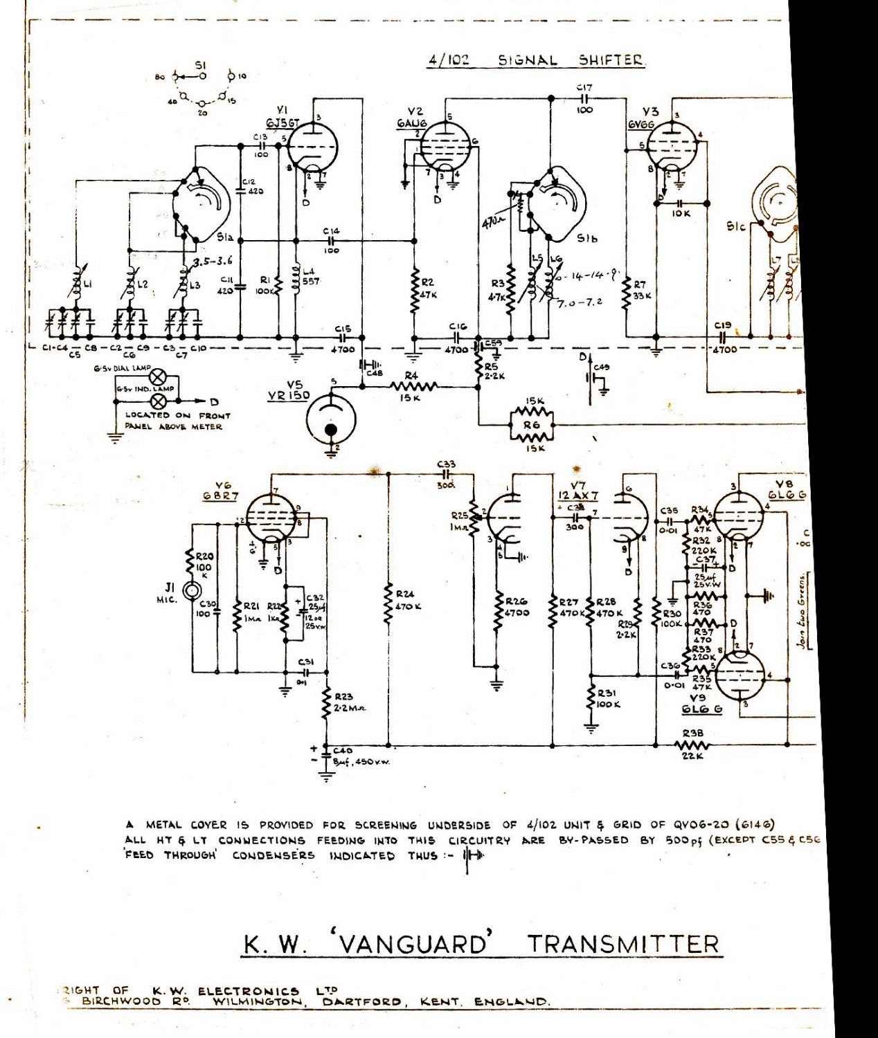
KW Vanguard MK1 Schematic Diagram (revision 5)

Last Updated – 16th December 2013

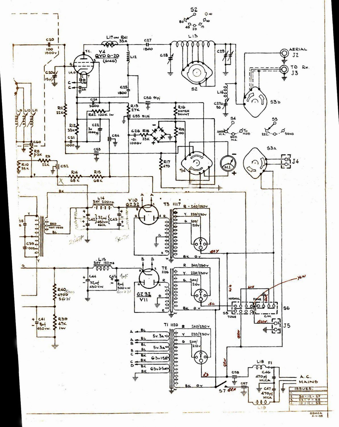
KW Vanguard MK2 Schematic Diagram (revision 4)

Last Updated – 16th December 2013

Last Updated on  14th February 2016 by Ray Farrer (G3VEQ)

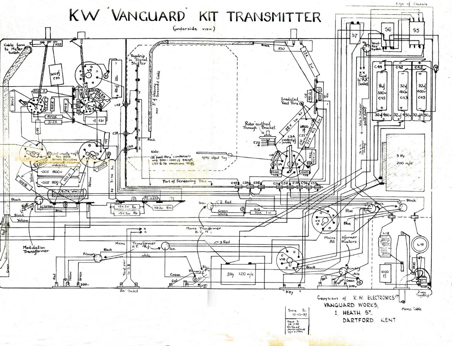
KW Vanguard MK2 Chassis Diagram (revision 1)

Last Updated – 16th December 2013

This is obviously not yet complete, but it is taking longer than  I would hope to get the information correct, so I don’t expect this to be complete or correct for ages yet!

Please note that the colours that I have used are not the original colours, I started off trying to use the original colours but as I have added more connections it was becoming a little difficult to read, so I started to add different colours where needed, sorry if this causes any problems for anyone…

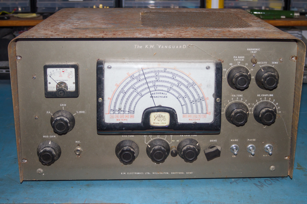
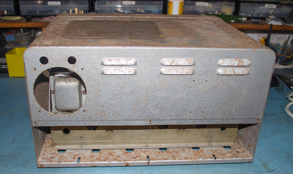
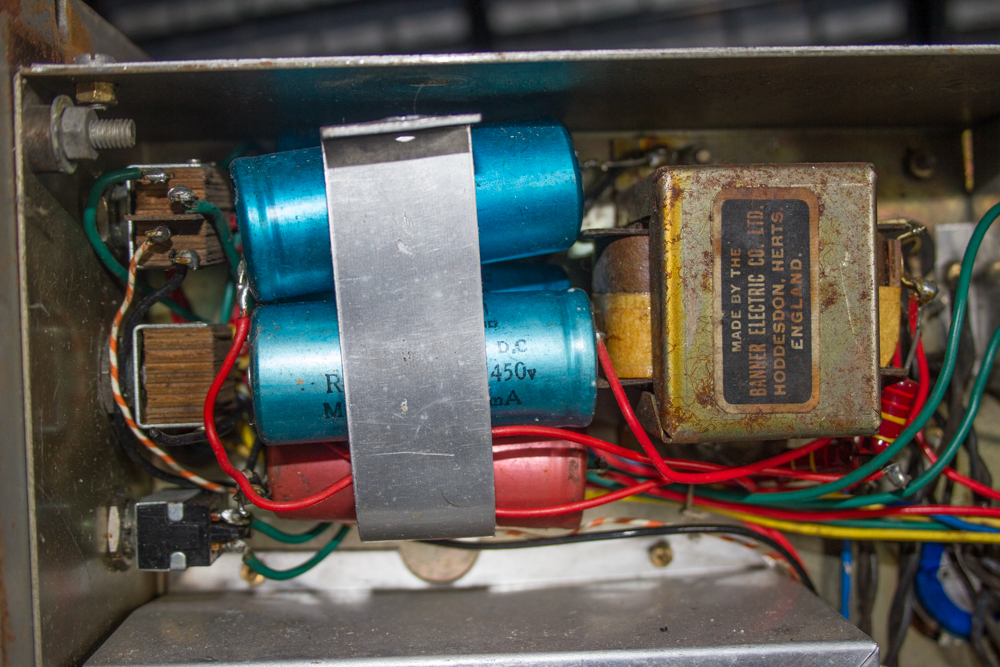
KW Vanguard MK2 Inside Layout (revision 1)

Last Updated – 16th December 2013

This also is obviously not yet complete, but hopefully I will get this one updated quite shortly, please check back soon to see any updates.

KW Vanguard MK2 Parts List

Bridge Rectifiers

Br1 =

Capacitors

C1 =
C2 =
C3 =
C4 =
C5 =
C6 =
C7 =
C8 = 120pF
C9 = 150pF
C10 = 270pF
C11 = 420µF
C12 = 100pF
C13 = 420pF
C14 = 100pF
C15 = 4700pF
C16 = 4700pF
C17 = 100pF
C18 = 10KpF
C19 = 4700pF
C20 = 100pF (1500v)
C21 = 1000pF (Ceramic)
C22 = 15pF Air Spaced Capacitor (PA Grid Tune)
C23 = 50pF Air Spaced Capacitor (Harmonic Trap)
C24 = 3600pF (Silver Mica 1000v)
C25 = 1800pF (Silver Mica 1000v.)
C26 = .01µF (1000v)
C27 = 1800pF (Silver Mica 1000v)
C28 = 200pF Air Spaced Capacitor (PA Tune)
C29 = 500pF Air Spaced Capacitor (AE Coupling)
C30 = 100pF (Ceramic)
C31 = 0.1µF
C32 = 25µF (Electrolytic)
C33 = 33pF (Silver Mica)
C34 = 33pF (Silver Mica)
C35 = 0.01µF
C36 = 0.01µF
C37 = 25µF (25v Electrolytic)
C38 = 0.005µF (800v.)
C39 = 0.005µF (800v.)
C40 = 8µF (450v Electrolytic)
C41 = 8µF (450v Electrolytic)
C42 = 32µF (450v Electrolytic (in Series))
C43 = 32µF (450v Electrolytic (in Series))
C44 = 32µF (450v Electrolytic)
C45 = 8µF (500v Electrolytic)
C46 = 470pF (Silver Mica 500v)
C47 = 470pF (Silver Mica 500v)
C48 = 500pF (Feed Through Ceramic Capacitor)
C49 = 500pF (Feed Through Ceramic Capacitor)
C50 = 500pF (Feed Through Ceramic Capacitor)
C51 = 500pF (Feed Through Ceramic Capacitor)
C52 = 500pF (Feed Through Ceramic Capacitor)
C53 = 500pF (Feed Through Ceramic Capacitor)
C54 = 500pF (Feed Through Ceramic Capacitor)
C55 = 91pF (Feed Through Ceramic Capacitor)
C56 = 91pF (Feed Through Ceramic Capacitor)
C57 = 500pF (Feed Through Ceramic Capacitor)
C58 = 500pF (Feed Through Ceramic Capacitor)
C59 = 500 pF (Feed Through Ceramic Capacitor)
C60 = 500 pF (Feed Through Ceramic Capacitor)
C61 = 500pF (Feed Through Ceramic Capacitor)
C62 = 22pF (Silver Mica)

Switches

S1 = VFO Switch (3 Way Wafer Switch)
S2 = PA / Band Change
S3 = Send / Receive
S4 = Meter Function
S5 = Tune / Normal Changeover Switch
S6 = CW Phone Changeover Switch
S7 = Mains On/Off


SA1 = 80/160 Meter Band Switch

Transformers

T1 = (1120) Mains Transformer
T2 = (1116) Modulation (High Tension)
T3 = (1117) RF (High Tension)
T4 = Fixed Ratio Modulation Transformer

3-Way Voltage Selectors

VS1 = Voltage Selector (for RF Transformer)
VS2 = Voltage Selector
VS3 = Voltage Selector (for Mains Transformer)

Fuses

F1 = 5 Amp

Sockets

J1 = Microphone (1/4″ Jack Socket)
J2 = Aerial (SO-239)
J3 = Receiver (SO-239)
J4 = Receiver Muting (2 Pin Socket)
J5 = CW Key Socket (2 Pin Socket)
J6 = 230 VAC

Inductors

L1 =
L2 =
L3 =
L4 = 557
L5 =
L6 =
L7 =
L8 =
L9 =
L10 =
L11 =
L12 = RF Choke
L13 = Geloso Tank Coil
L14 = 3H (200 mA Choke)
L15 = 3H (120 mA Choke)
L16 = Harmonic Rejector
L17 = Anti-Parasitic Choke
L18 = Mains Choke
L19 = Mains Choke
L20 =

Resistors

R1 = 100k (2 watt)
R2 = 47k (2 watt)
R3 = 4.7k (2 watt)
R5 = 470 (2 watt)
R6 = 3.5k (10 watt)
R7 = 33k (2 watt)
R8 = 3.3k (2 watt)
R9 = 22k (2 watt)
R10 = 30k (Drive Control – Potentiometer)
R11 = 22k (2 watt)
R13 = 10k (10 watt)
R14 = 10k (2 Watt)
R15 = 22k (2 Watt)
R16 = Meter Shunt (Meter Shunt)
R17 = 470 (2 watt)
R18 = 33k (1/2 watt)
R19 = 100 (1/2 watt)
R20 = 100k (1/2 watt)
R21 = 1M (1/2 watt)
R22 = 1k (1/2 watt)
R23 = 2.2M (1/2 watt)
R24 = 470k (1/2 watt)
R25 = 1M (Mod. Gain Control – Potentiometer)
R26 = 4.7k (1/2 watt)
R27 = 470k (1/2 watt)
R28 = 470k (1/2 watt)
R29 = 2.2k (1/2 watt)
R30 = 100k (1/2 watt)
R31 = 100k (1/2 watt)
R32 = 220k (1/2 watt)
R33 = 220k (1/2 watt)
R34 = 47k (1/2 watt)
R35 = 47k (1/2 watt)
R36 = 470 (2 watt)
R37 = 470 (2 watt)
R38 = 22k (1 watt)
R39 = 47k (1 watt.)
R40 = 4.7k (5 watt.)
R41 = 33 (Anti-parasitic Choke)
R42 = 100k (1 Watt)

Tag Boards

Tag 1 = 4 Way Tag Strip
Tag 2 = 6 Way Tag Strip
Tag 3 = 8 Way Tag Strip
Tag 4 = 5 Way Tag Strip
Tag 5 = 9 Way Tag Strip
Tag 6 = 18 Way Tag Board

Valves

V1 = 6J5GT (“Clapp” Oscillator)
V2 = 6AU6 (Buffer-Multiplier)
V3 = 6V6GT or 6L6G (Driver/Tripler)
V4 = 6146 (or QVO 6-20)
V5 = 6BW6
V6 = 6BR7 (Speech Amplifier)
V7 = 12AX7 (Amplifier and Phase Inverter)
V8 = 6L6G (Push Pull Modulator)
V9 = 6L6G (Push Pull Modulator)
V10 = GZ32
V11 = GZ32
V12 = VR150
V13 = VR150

Material to Download

Advert first published in an early RadCom magazine.

KW Vanguard - Advert

KW Vanguard – Advert

Icon
1.59 MB 13 downloads

The VMARS Newsletter – Issue 21 – KW Vanguard

The VMARS Newsletter – Issue 22 – KW Vanguard Some Further Notes

KW Vanguard Instruction Manuals (Unknown Source)

Article from Shortwave Magazine on the constructing and testing the KW Vanguard

Article from Shortwave Magazine on the modifying the KW Vanguard for operation on Top Band

Shortwave Magazine article on modifying the KW Vanguard to push 100W from 1965

Not really for the KW Vanguard but this article from Shortwave Magazine from 1958 shows why KW Electronics decided to use the Geloso units, worth a read.

Article from Shortwave Magazine regarding the GELOSO Signal Shifter 4-102 VFO that is fitted to the KW Vanguard

Shortwave Magazine article on the Geloso 4-104 VFO from 1958

A kind of Idiots Guide to the Voltages expected in the KW Vanguard

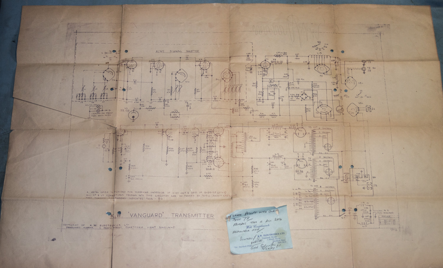
Schematic Diagram (Source Unknown)

Printable Version of the GELOSO Scale just in case yours needs replacing.

Hand Drawn Cathode Follower modification for the KW Vanguard (Source  G3VEQ)

Scan of the original instructions to operating on 160m with a KW Vanguard (Source  Guy Roberts G0UKN)

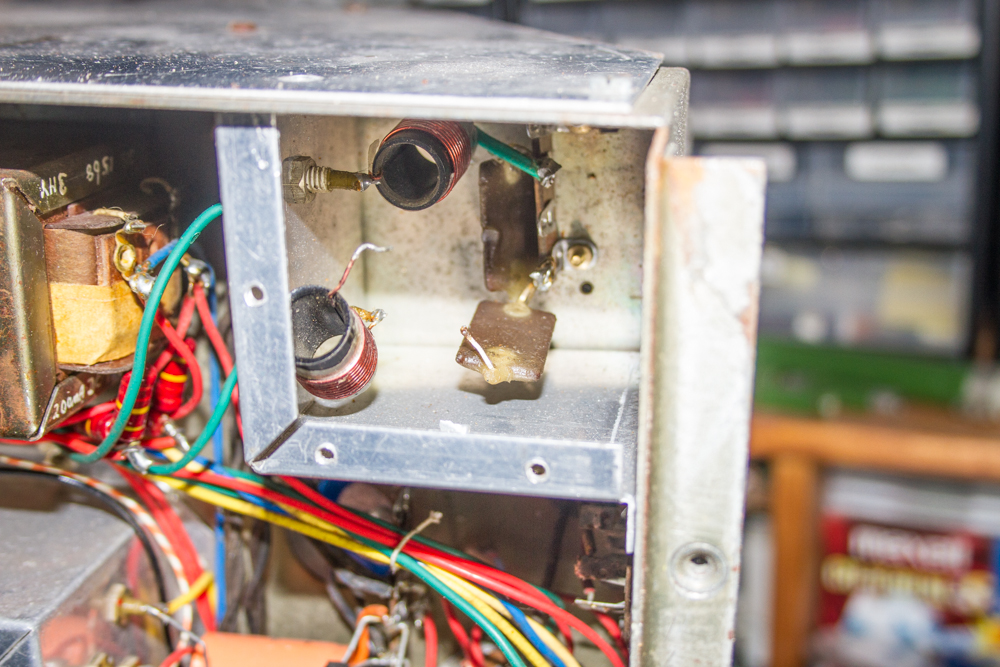
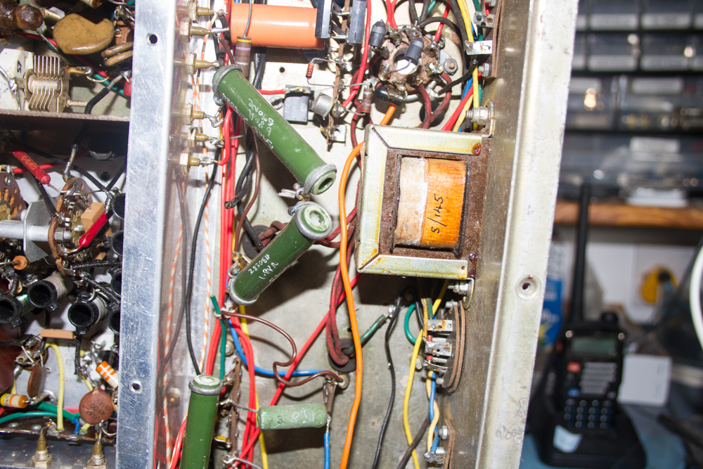
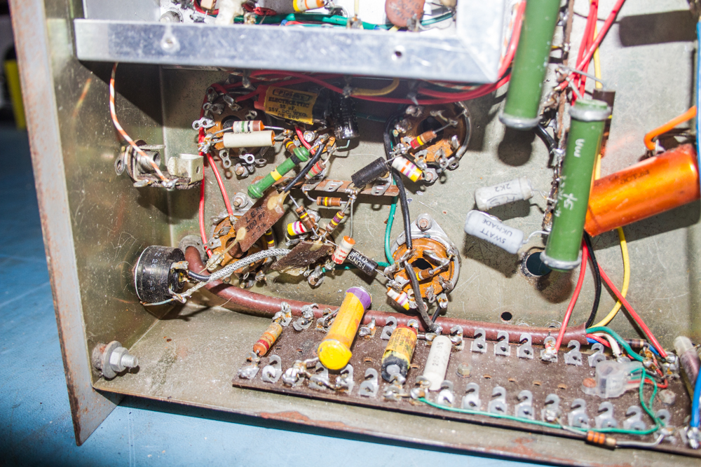
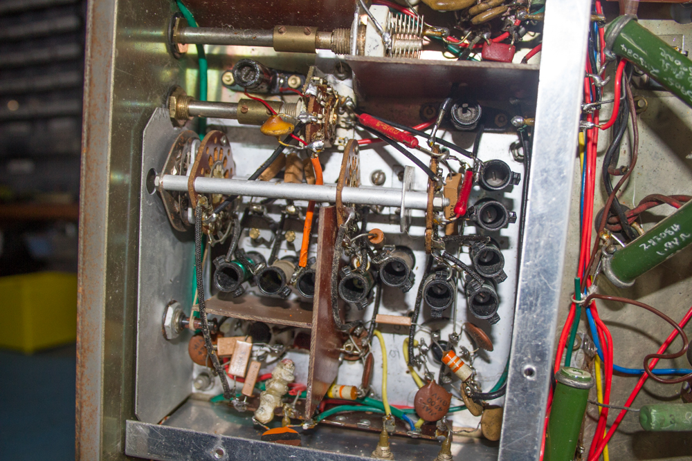
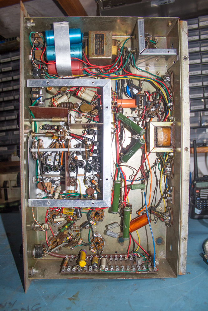
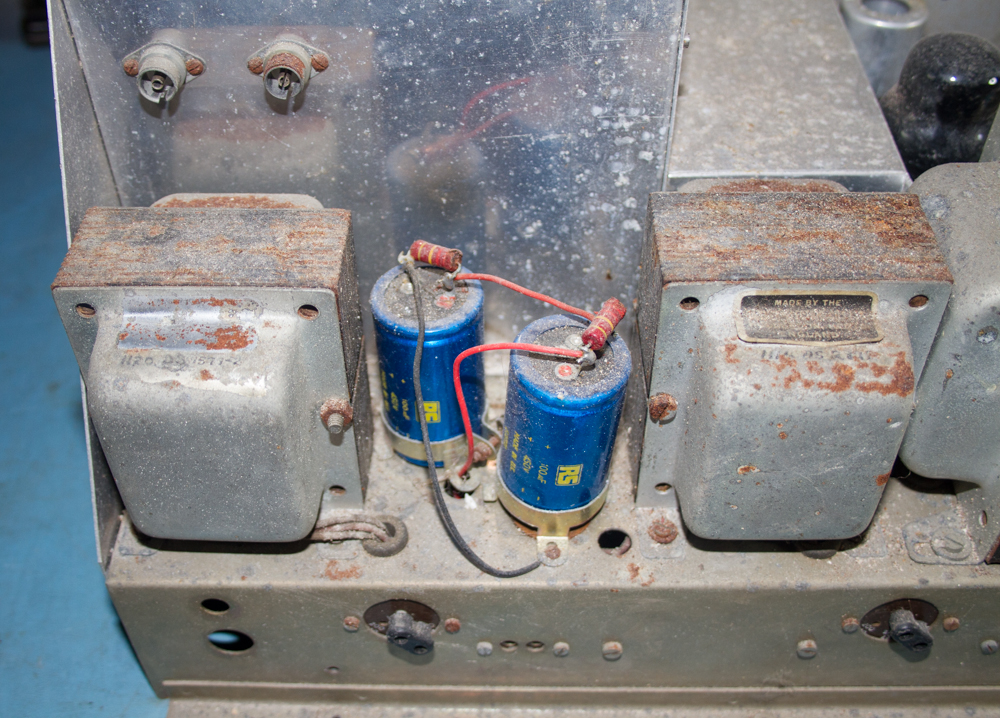
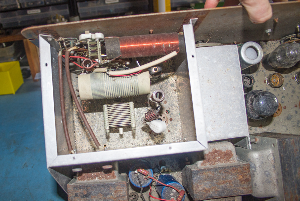
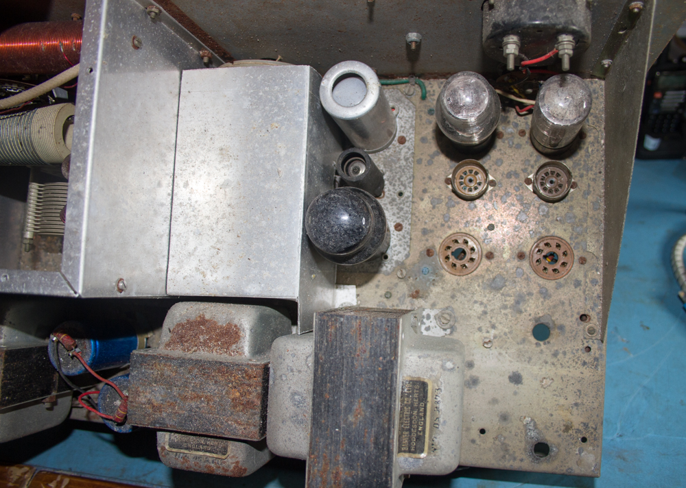
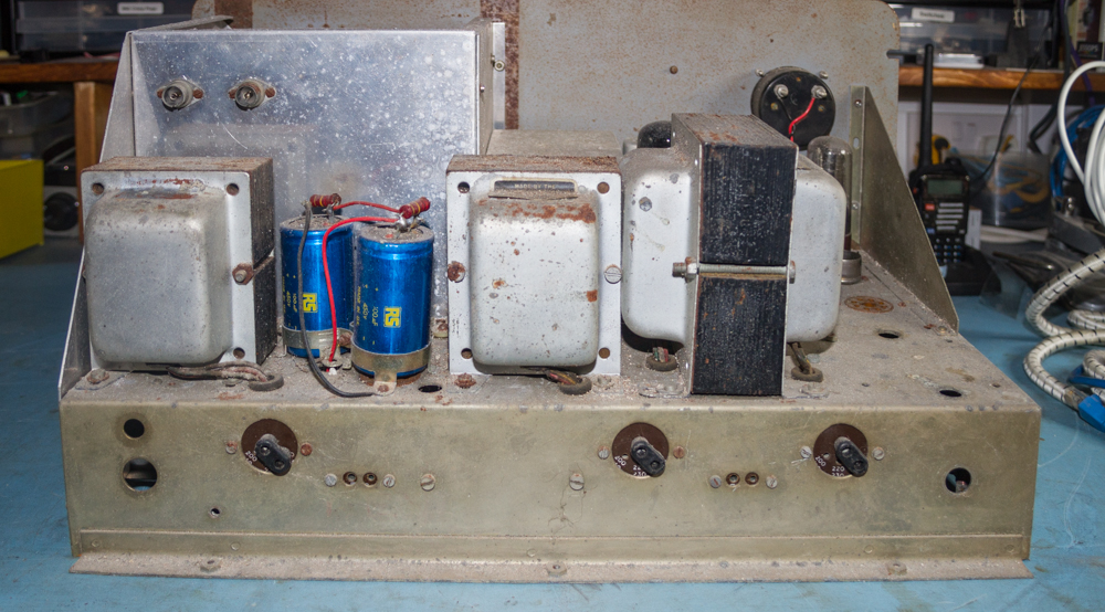
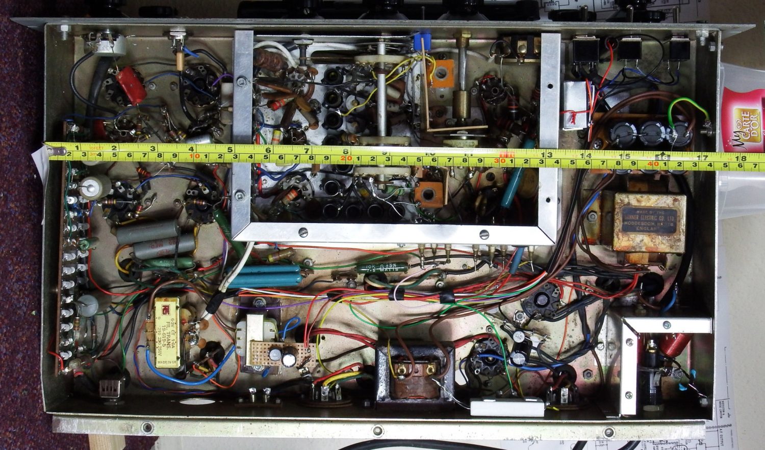
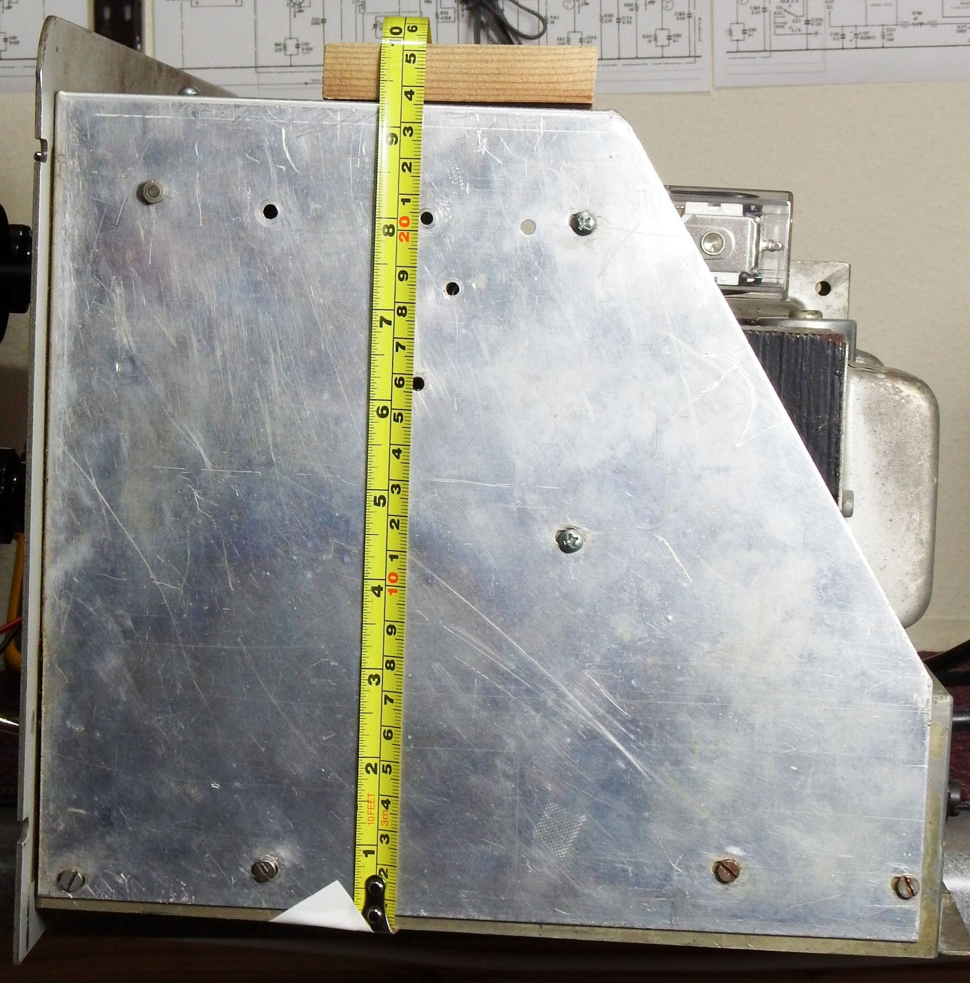
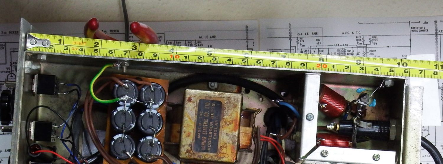
Some useful photos of the dimensions of the KW Vanguard Chassis uploaded by Ray Farrar (G4KXF)

Scan of the original Build Notes for the KW Vanguard (Source  Guy Roberts G0UKN)

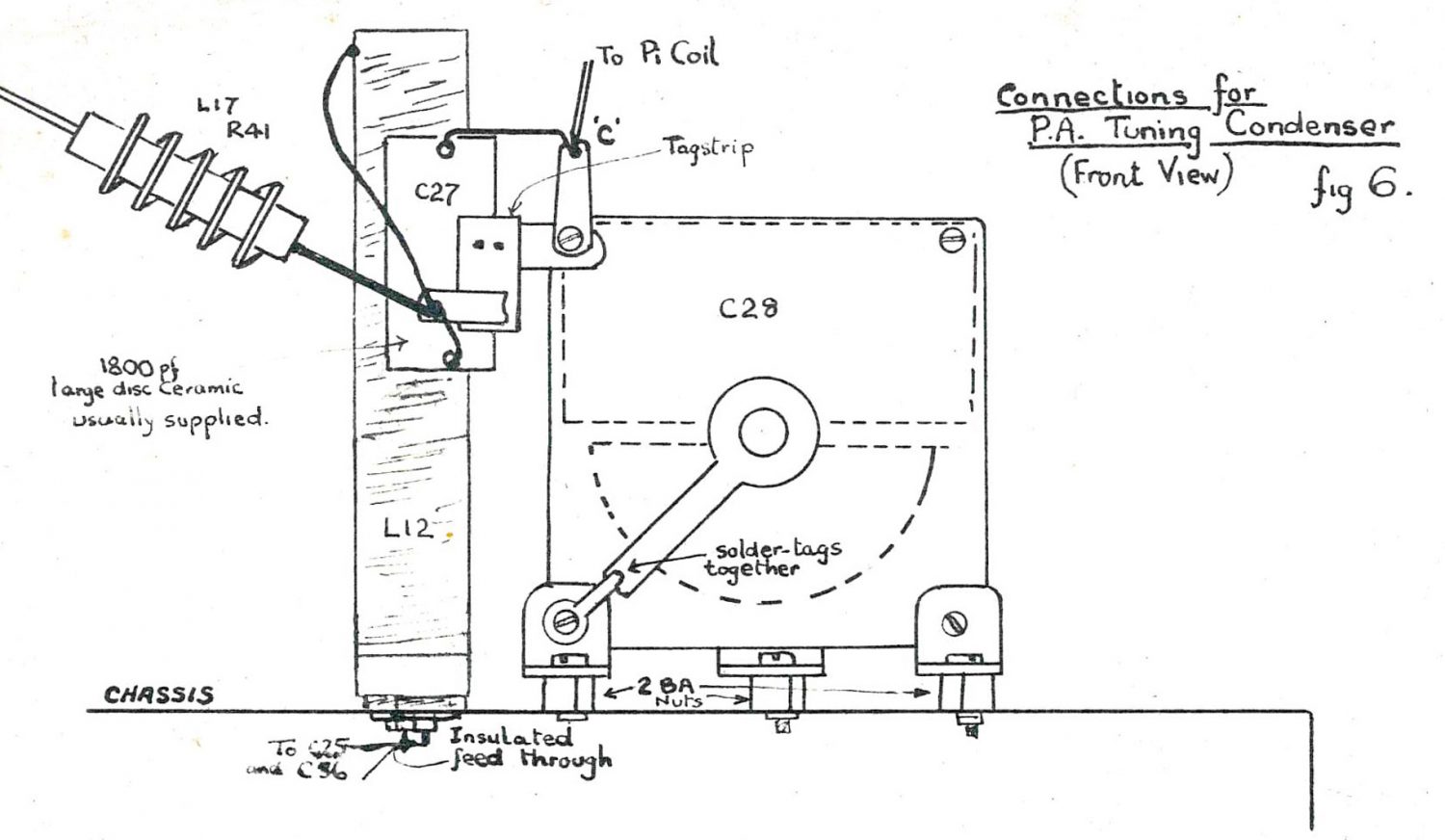
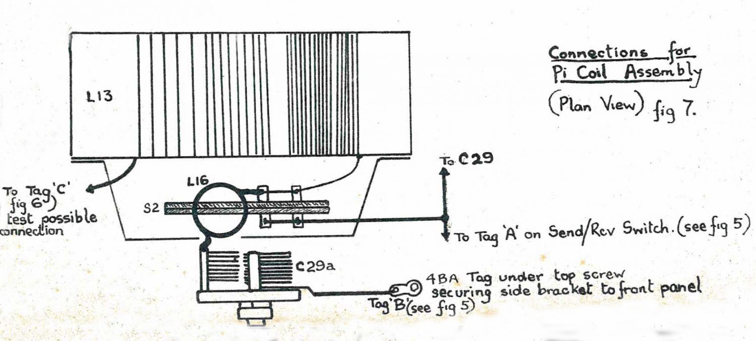
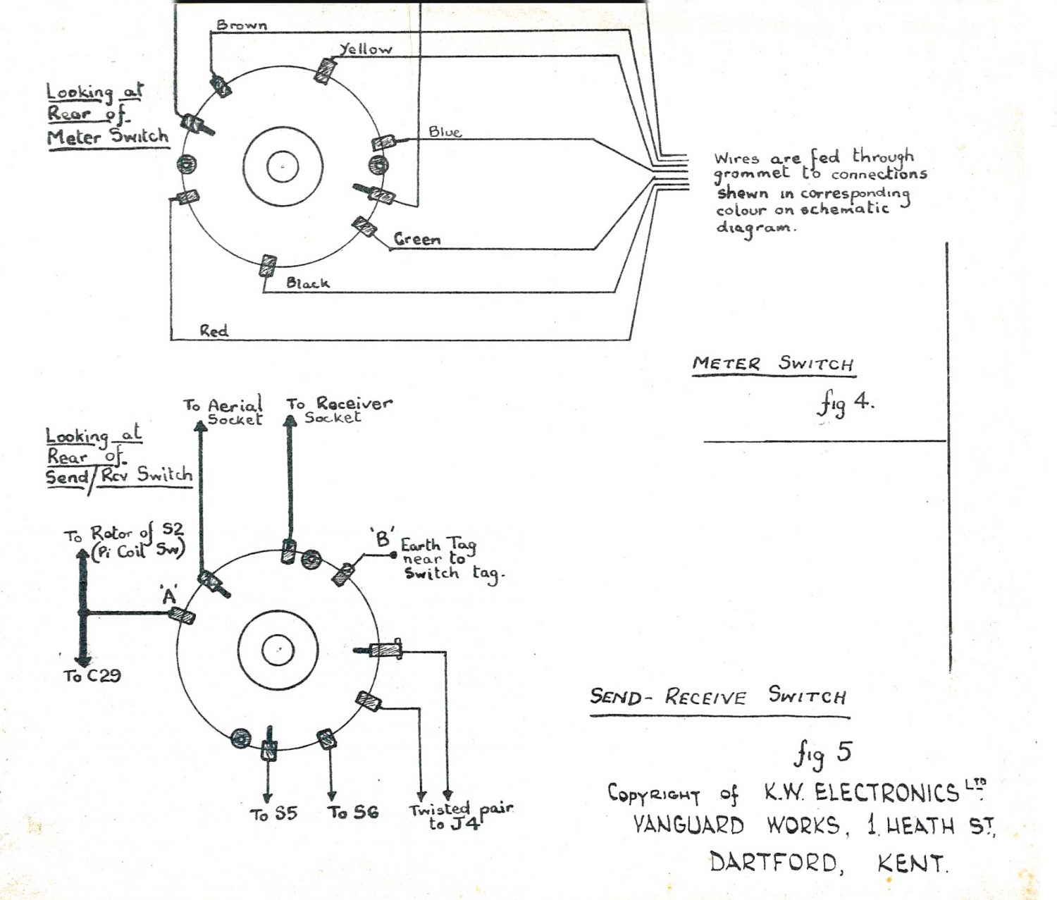
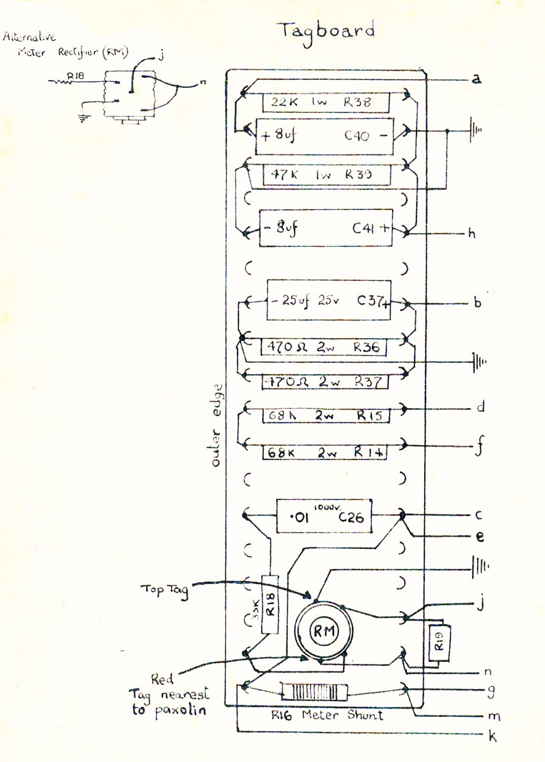
Some very useful notes and drawings on the Wiring of the KW Vanguard (Source Guy Roberts G0UKN)

Original scan of the KW Vanguard Mk II – Parts List (Source Guy Roberts G0UKN)

Scan of the original Operating and Tuning Procedure from 1963 (Source Guy Roberts G0UKN)

Even Snowey was helping check the schematic diagram of the KW Vanguard

It has taken me a while to get the Schematics done, not just because I am waiting on feedback and information from other (Very Helpful) sources, but also because my Cat (Snowy) refuses to budge and demands attention whenever I am sat on the computer, and loves nothing more that head butting the Wacom pen when I am trying to use it, Daft Puddie Tat !…

I have not done much of late, mainly to being a little pissed off with a few comments that I have received of late.

Now most of the amateurs that have contacted me have been so very helpful, and i will add a section to the bottom of this page to thank them, but just a few seem to find what i am trying to do as ‘wrong’, or in there terms “You should not be playing with things that you don’t understand”, or just in the way that they answer you in some of the forums, you get the feeling (almost too bluntly), that because of the lack of understanding for such a challenge that I really should not be even asking them for help!

Thankfully though like I have already said, most of the people helping that have contacted me by telephone or e-mails are generally really helpful (as amateurs should be), but it really pisses me off when you get some arrogant twat make stupid comments, and basically make you feel that you are wasting their time and obviously my own, trying to do something that I do agree is out of my comfort zone.

I have been lucky to know a few amateurs that still hold on to the old values, those that are very helpful, and are more than willing to pass on anything to those willing to listen, but you cannot help getting pissed off when you get the odd twat that does not really think the sharing of information should go on, sadly a lot of these are amateur radio operators, which makes it even worse, being on the receiving end of these comments I really hope that I never turn into one of these sad individuals that carry around a soapbox to obviously stand on and moan about things, usually just because that is all they can do, if they cannot offer anything helpful, they should just keep there mouth shut and stay out of it!

Sorry about this guys – but the helpful ones know who you are….

And whilst on the subject of getting help from people, here is what I received today (18th December 2014), I got an envelope from Steve Mulligan (G4CBA) who very kindly sent me an original copy of a drawing that was sent to him by G3XKY of KW Electronics Limited. This will be a nice addition to the radio. Thanks Steve…

KW Vanguard Original Schematic Diagram supplied by KW Electronics, thanks to Steve Mulligan (G4CBA)

One of the documents that I came across on the KW Electronics Group.io page was some scan from original documents provided by Guy Roberts (G0UKN), the original from Guy is above, but here are the images within te document, I managed to clean them up a little but sadly the original scans are not too great with regards to the more detailed drawings, but here goes anyway.

A REQUEST – I have a Drum Scanner here which is capable of scanning at incredibly high resolutions anything up to A0 in size (scanner will scan 1200mm x 900 mm ) in one go, if Anyone would be willing to let me borrow any original drawings then I would be more than happy to provide them with high resolution copy in any format that they would like along with the originals back after scanning. I would also be happy to cover the cost of recorded delivery to me so that your drawings are safe to and from me.

KW Vanguard - Connections for PA Tuning Condenser
KW Vanguard - Connections for Pi Coil Assembly
KW Vanguard - Switch Wiring

Sadly the two images below were as good as I could get, there is quite a bit missing from the scan to join them in any way, hopefully I can get hold of a copy one day  to make the project complete but until then you guys will have to do with my own version above.

KW Vanguard - Schematic Part 2
KW Vanguard - Schematic Part 1
KW Vanguard - Transmitter Wiring
KW Vanguard - Tagboard Layout

And another big thanks to Guy Roberts G0UKN for the originals and taking time to upload them to the KW Electronics Group.io page.

Thanks for the Help!

Mike Farrent (GD4BEG)

For the very kind donation of all of the equipment that he has given me which included (in a very small part) this KW Vanguard, and because of his kindness I wish to restore this to full working order, however long it takes, just in the hope that one day I may be able to get a photo of him using the equipment at the shack.

James Cookson (G4XWD)

James provided me with some very nice photos of the original schematics that he had, these have been of great help to me and put me right on a few occasions when no other help has been forthcoming, really appreciate the help Jim…

Rob Hurst (G7HIU)

For one of the many Audio Transformer that I have received, thanks to Rob and the others I have one of the major parts that were missing from my build!

Graham

(Forum Moderator – UK Vintage Radio Repair and Restoration Forum)

Graham has been very useful to me, he has often told me when I have gone wrong with the schematic, I sometime feel from his wording that I have annoyed him somewhat, but hopefully this is not the case, like most things, when you try to learn something new, you need people like Graham around to help you see where you go wrong, this is something he has done well, and it is much appreciated.

Terry Hart (G3FVO)

Early on with the project I had placed an advert in RadCom for a Woden UM1 Transformer, and someone (who I am afraid I cannot remember as I stupidly forgot to write down his call sign when he called me, but who I am very thankful to) called me to say that he had spotted my Wanted advert and did I see the For Sale section as it had a working KW Vanguard mentioned. I hadn’t received my copy at this time so I got the information off this person and called Terry, and after just a few minutes on the phone I had got from him a very clean KW Vanguard that will be used for a reference to restore this old one that I have here. Terry has been VERY helpful indeed and I really do offer the best of thanks for letting me have and cherish this lovely example of a KW Vanguard transmitter that he has in his collection, just a shame I could not afford the rest of the stuff that he was selling…

Joan van Pamelen (VK5KYO)

Out of the blue and from the hopefully warmer climates of Australia I got a great bunch of e-mails regarding my Schematics that I had uploaded here, pointing out a few errors and adding a few notes here and there. It looks as though he is hopefully going to do the same sort of restoration project, having an old KW Vanguard that is in about the same sort of condition, He sent me some great photos as well of his own KW Vanguard to see what his looked like. Thanks for the help Joan, and hopefully you will be able to finish yours as well…

Steve Simmons (G4HXY)

Another one of those nice e-mails out of the blue was from Steve regarding the missing transformers and valves, I really appreciate the help Steve…

Steve Mulligan (G4CBA)

Thanks very much for the original Schematic that Steve very kindly posted to me, including the complement slip that was enclosed with it which was the original sent from KW Electronics Limited by G3XRY, Thanks for this, it will stay with the radio and it is also very much appreciated…

David Wells (M0CEM)

For all the information that he sent me, especially the notes on his own project that will prove to be invaluable. VERY much appreciated…

R.M. Volck (GW3RKV)

Thanks for the Transformer that he sent me, another good candidate for the rebuild, and much appreciate the help.

Ray Farrar (G3VEQ)

Very kindly updated the Schematic and posted some photos that have become useful to the KW Electronics Group under groups.io. Much appreciate any help and guidance.

Colin Chidgey (G3YHV)

Thank you for a small but lovely collection of KW original Parts List/Order Forms for the KW Vanguard, it is so nice to be able to get hold of these and of course they will be taken care off, scanned in and uploaded for anyone else that is in love with these great little Transmitters. Thanks Colin, I really do appreciate these a lot.

Related Posts

Leave a Comment

This website uses cookies to improve your experience. We'll assume you're ok with this, but you can opt-out if you wish. Accept Read More

free counters

error: Content is protected !!