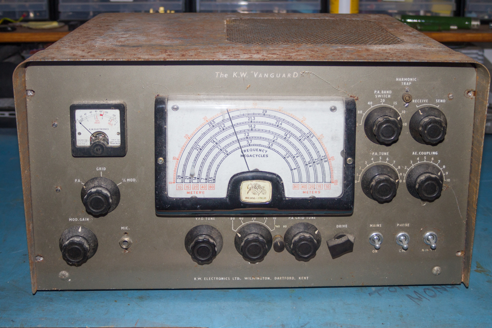
KW Vanguard Face Plate Removal and Other Metalwork
OK, this is where I kind of mess up a bit, but I will still show you where I went wrong so I hope anyone repeating this process will not make thew same mistake that I did, though thankfully, it is fixable, but I am sure that there is a neater way to do this, as it gets a little messy before I get the result that I was after.
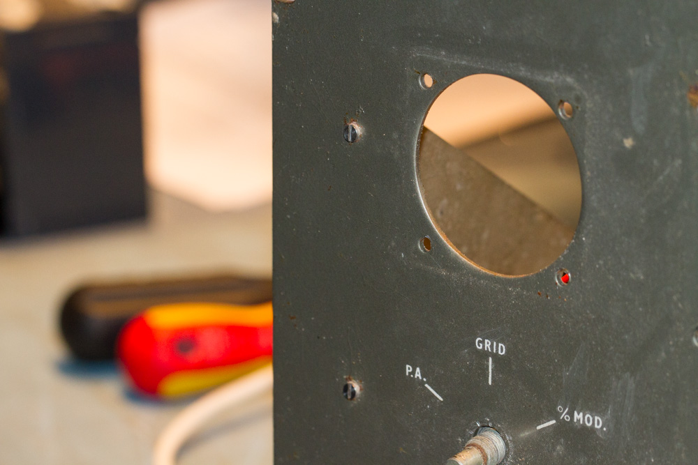
So to start to remove the face plate from the chassis I removed the two screws that fix the face plate to the screen next to where the meter was sitting.
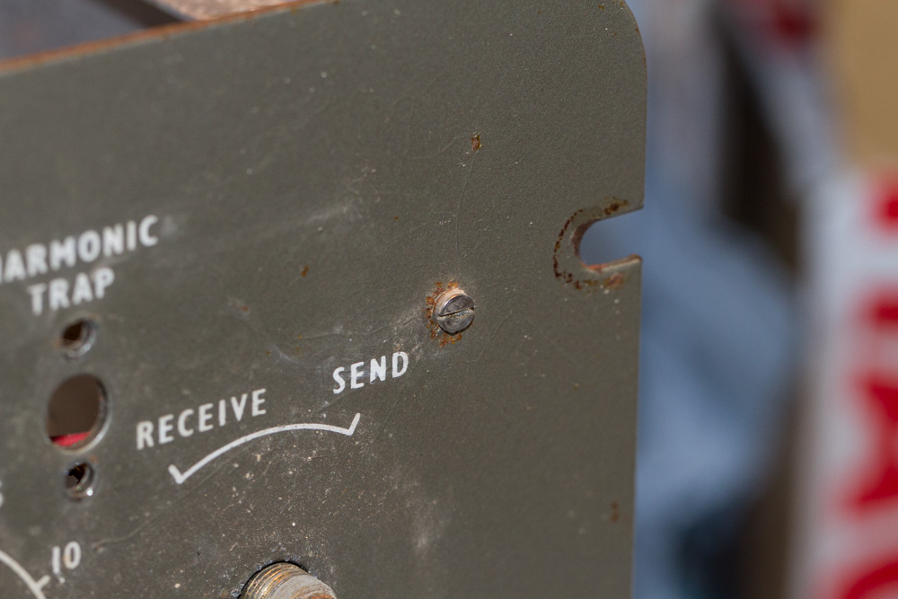
Then I removed the screw near the ‘Send/Receive’ switch on the right hand side of the face plate.
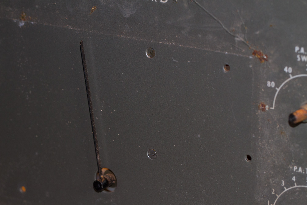
There are two countersunk screws that were behind the VFO dial that need to be removed.
Next to remove are the three countersunk screws around the ‘AE Coupling’ dial.
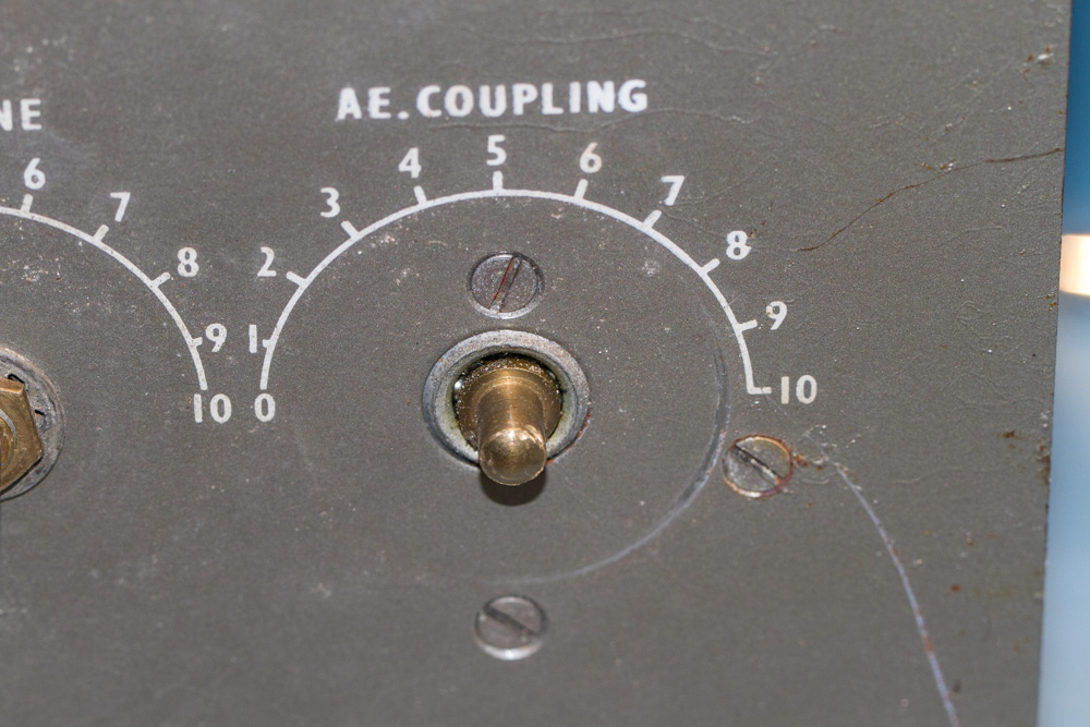
Now for the large dome head screws at the bottom of the face plate in each corner, and obviously once these have been removed the face plate will be quite loose and care needs to be taken here against any damage.
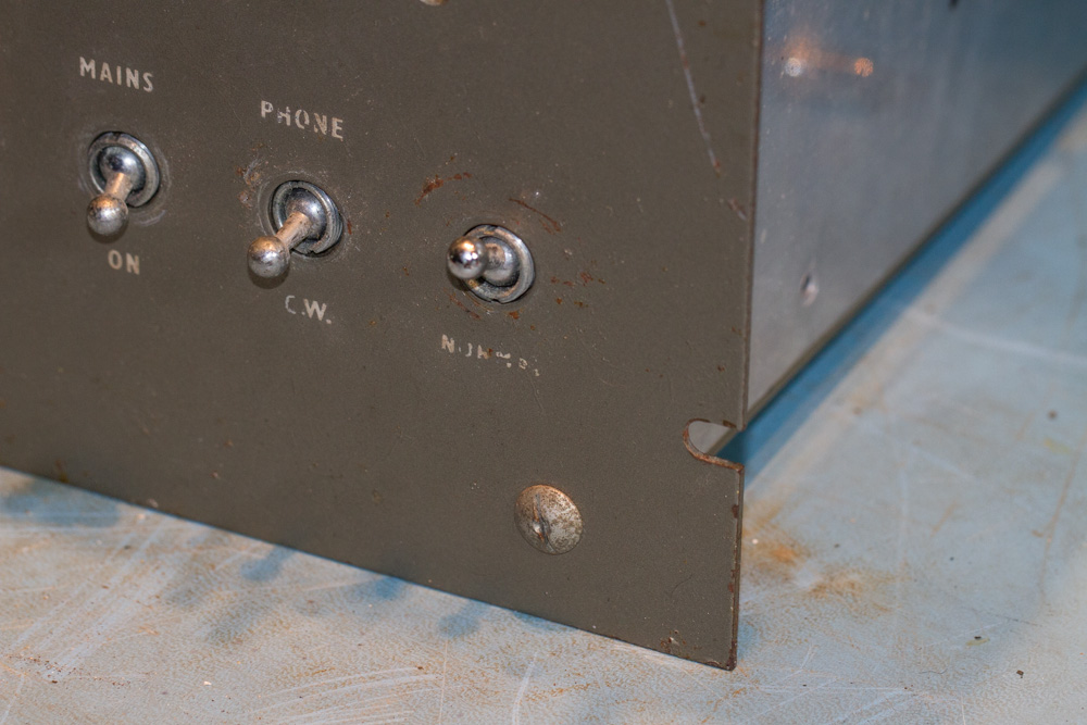
Now for the last of the large dome head bolts. As a note, make sure that you reassemble the bolts in the same rode as they came out, it may be many months before the unit is reassembled.
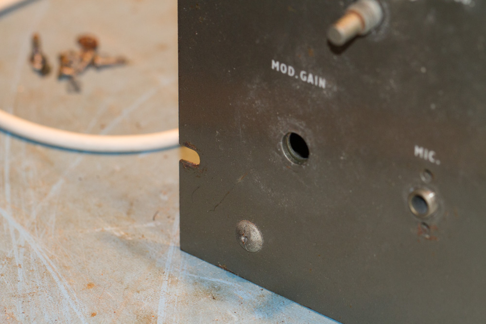
The front panel is now very loose, try not to make any sharp movements…
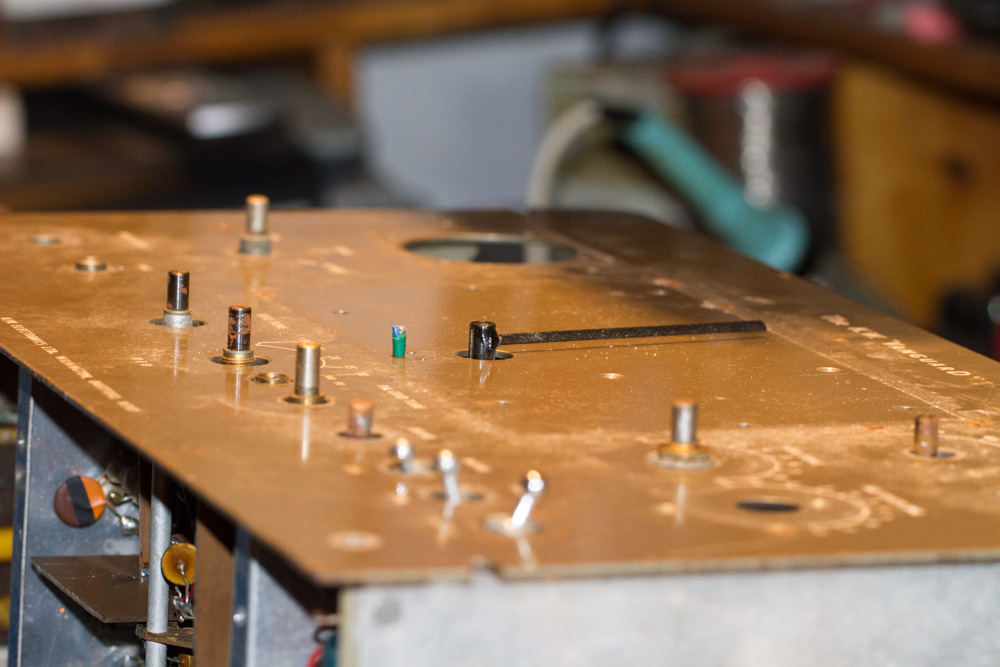
The hopeful idea here was that the face plate could be slide out without disturbing the VFO meter needle, but alas there was not enough give in the face plate due to the shielding at the rear of the unit.. As a note to all reading, Yes I had tried to remove the needle, especially as it does look to be a push fitting, but after applying as much force as I dare I chickened out thinking that to slide the face plate off and around the needle may just be the best option….
To make it possible to slide the face plate off and past the VFO meter needle I need to remove all the metalwork holding the faceplate in position, the first part to remove is the small triangular bit of shielding from the chassis.
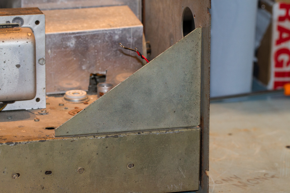
This was left in place by a single slotted bolt. and as with the rest of the bolts in this section, you will need to be ambidextrous with your fingers, thankfully I did not need to use pliers or a nut driver to hold any of the nuts on the underside of the chassis as most of mine were loose, but you will need to apply pressure to the nut to hold it whilst you unscrew the bolts. and remember to save the nuts and washers to be put away later.
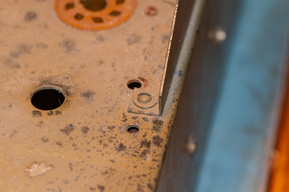
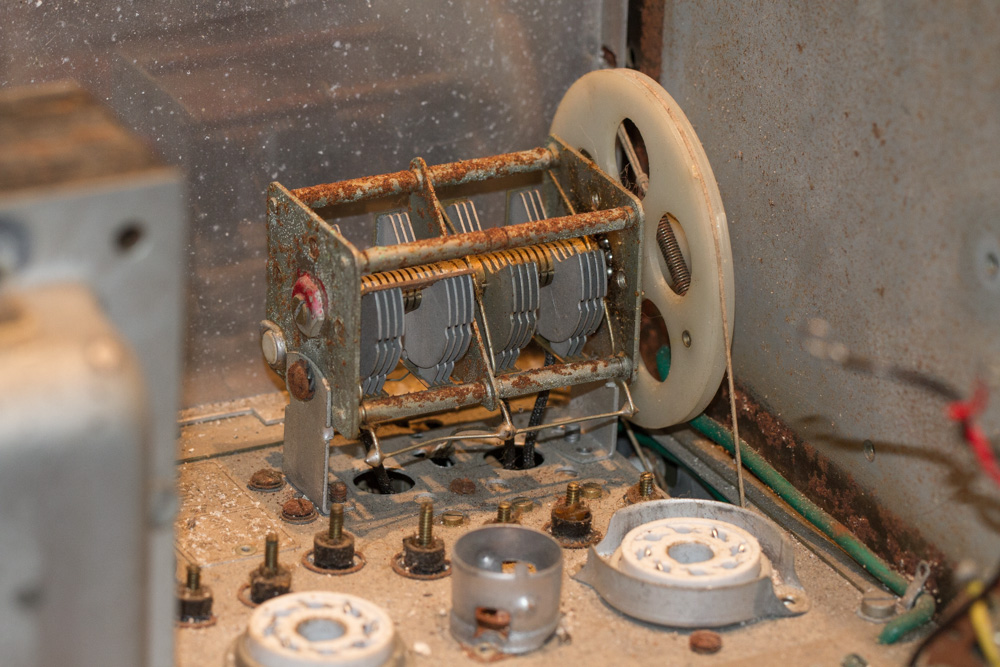
In my unit I had some poorly made bit of shielding which covered the VFO’s Air Spaced Capacitor, this was held in position with one of the Transformer bolts and was quite easy to remove.
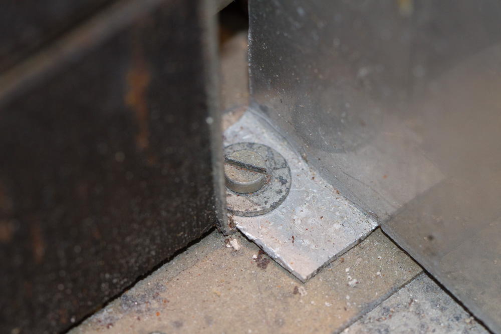
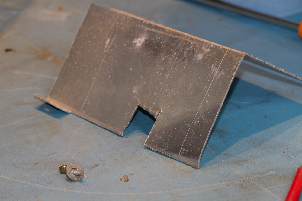
Although I will not be using this bit of shielding I will keep it as I may get one made up to fit properly and therefore this could be of use as a rough template.
Here is what was hidden underneath the make shift shield.
Now to the other side of the unit and we have to remove 4 fixings from this end shield plate to remove this from the chassis, the two vertical and somewhat rusty fixings are the first two self tapping screws that I have come across so far.
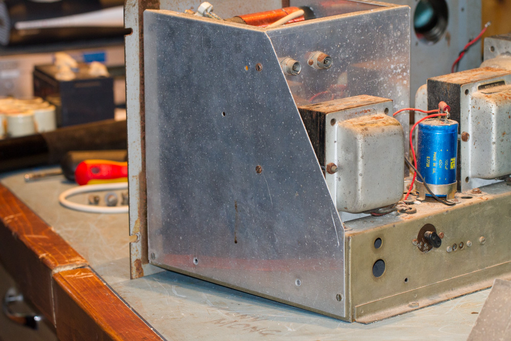
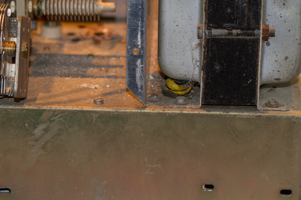
Not forgetting the last of the bolts hidden by the transformer.
Onto the rear of this box section and we have to 75 ohm sockets, I did not even attempt to unscrew these as the screws just look a little to far gone, instead I thought that I would just cut the wires on the back of the sockets.
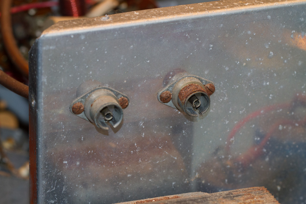
It is always wise to take loads of photos as you go, and especially of the switches and sockets that will be re-wired at a later date.
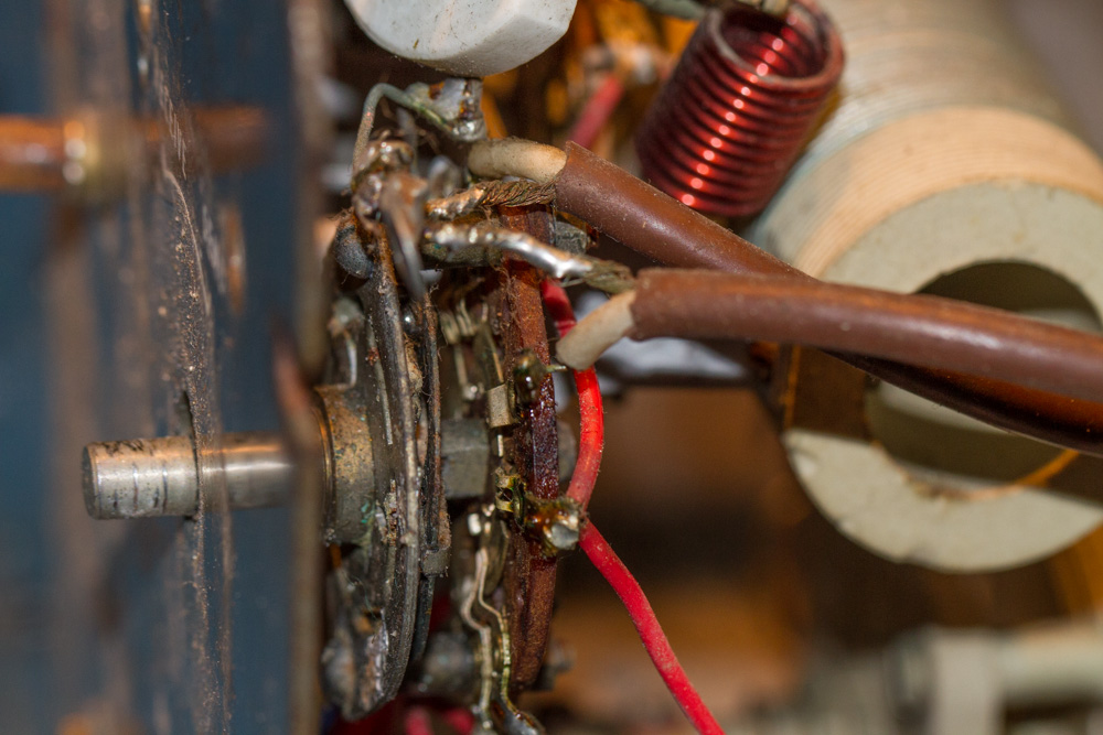
Next we need to remove the bolt that is holding the large coil inductor at the top of the shielding.
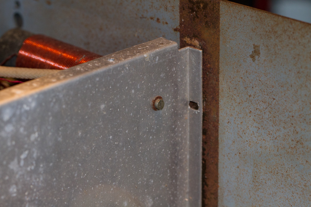
I replaced the screw in the end of this coil for safe keeping.
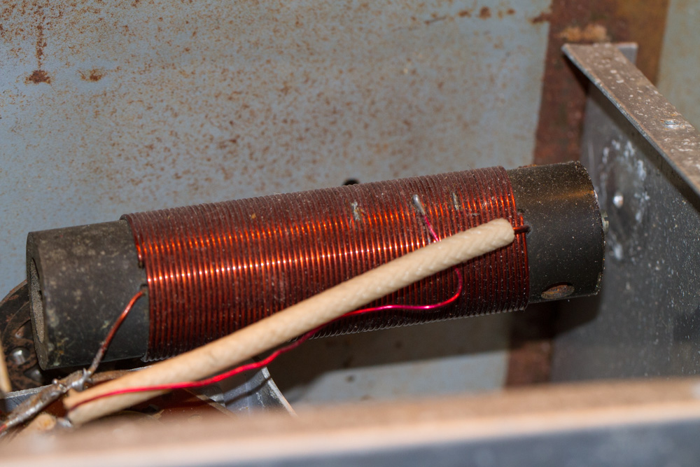
Now to remove the bolts that hold the shielding together.
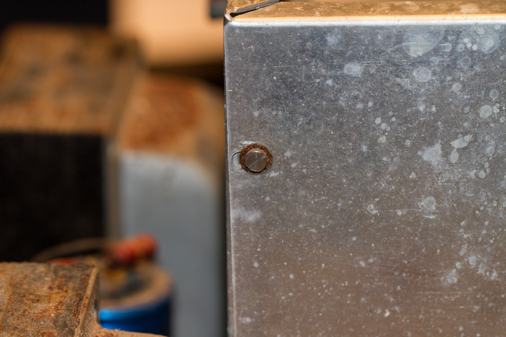
And another the bottom of the corner.
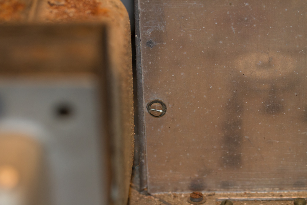
There are three bolts into the bottom of the chassis that also need to be removed to remove this plate from the unit.
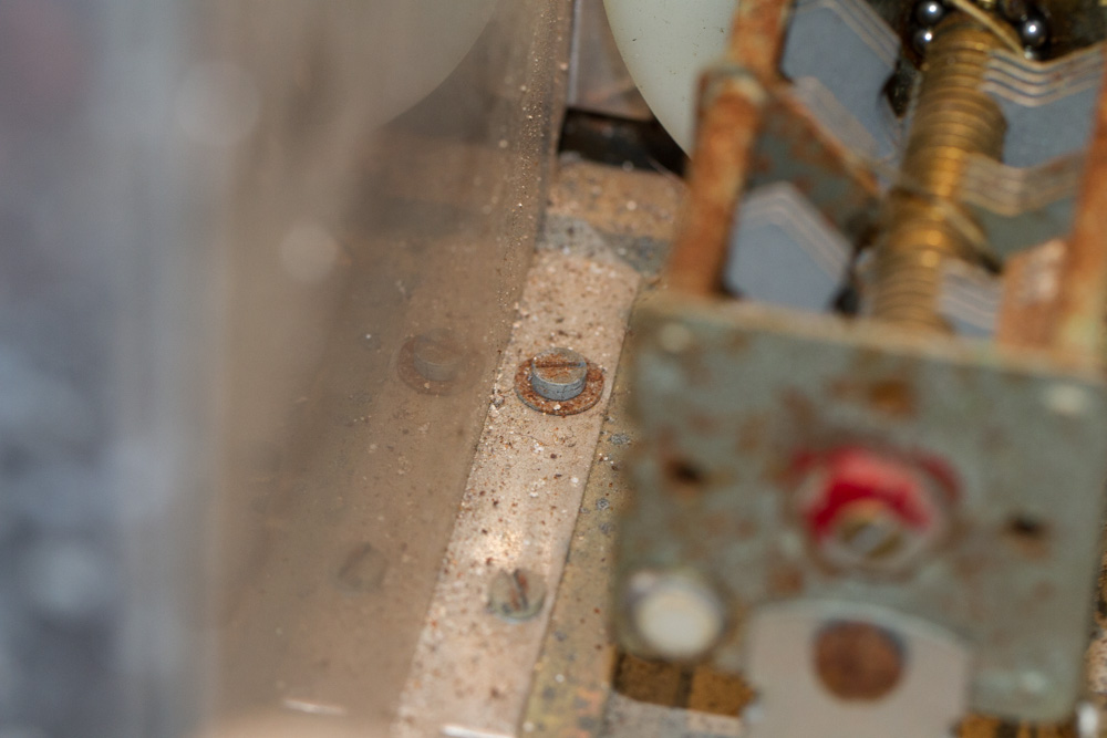
We can now remove the last of the valves in the unit (V5 – 6BW6).
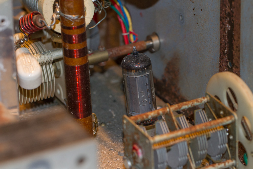
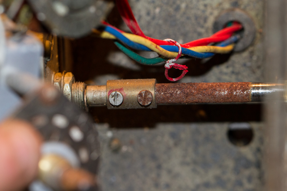
With all this removed we can finally get the the connection rod of the ‘PA Tune’ control, this can now be removed, in my case this was two steel nuts and bolts and both rusted, the first one came out OK, but I was not able to remove the rod from the connection block, the last bolt sheared off but not before loosening off the connection rod.
Now here is were it went a little wrong, and maybe there was another way to do this, but when I lifted off the face plate, I was trying my best to manoeuvre this around the VFO meter needle but it broke off whilst I was moving the front plate.
On the good side this was just soldered in place and as it came away very cleanly, I should not have a problem desoldering this on when I start to rebuild this unit.
So as a side note, I think the way that I went about this was far from perfect, and there is possibly another easier way to do this, but as I did not see this, I ended up breaking something, maybe I could have taken more care in removing the front face plate, but it will all turn out OK in the end, and at least the most important items are still intact, if not perfect, i.e. the Meter and the VFO Dial Face Plate.
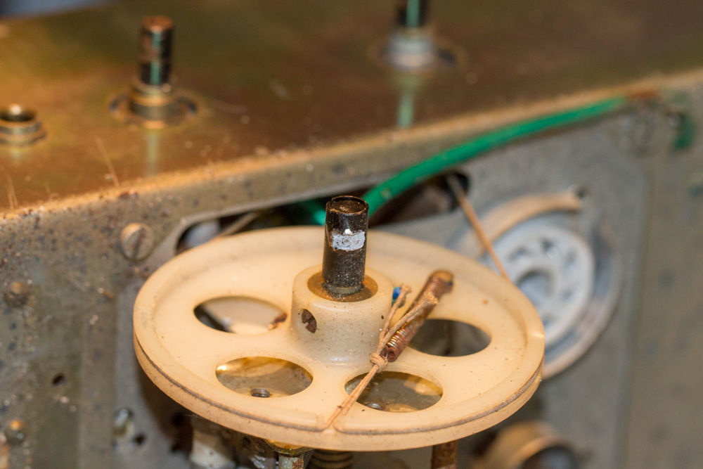
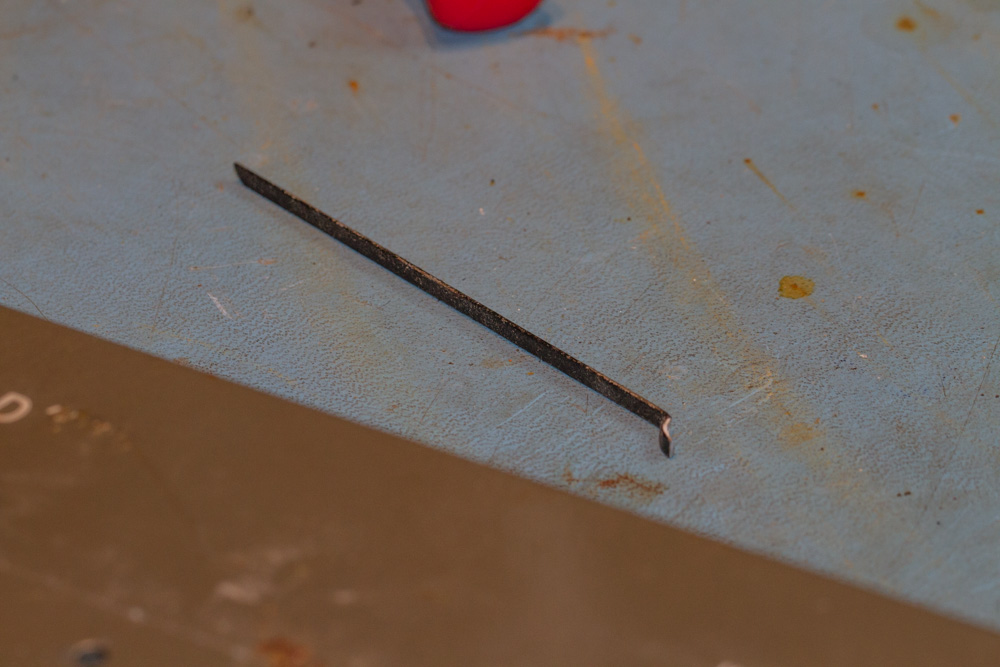
And what’s left…
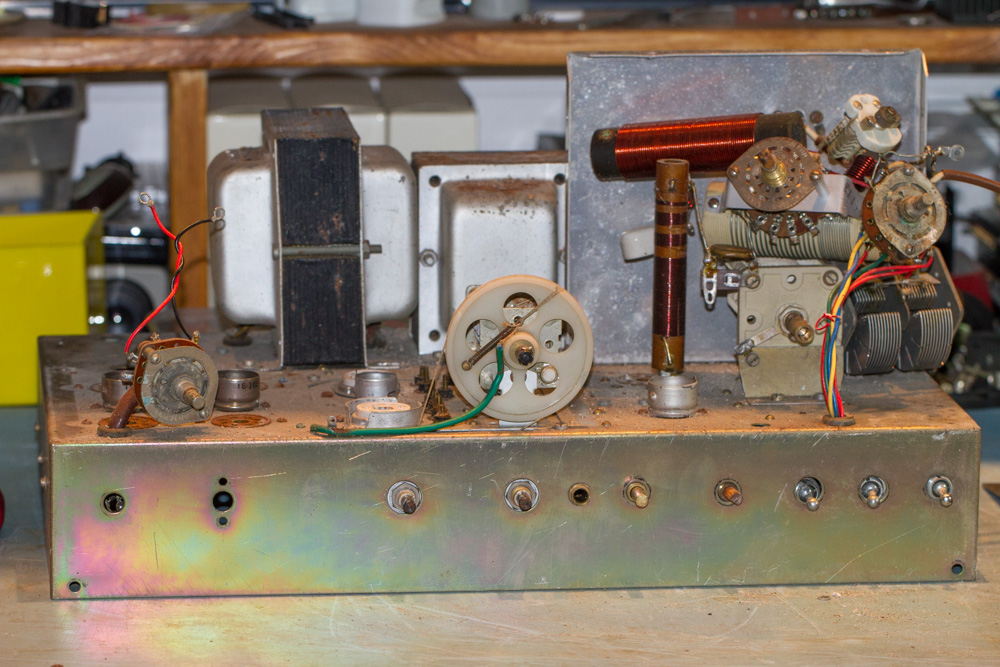
Now I must apologize for what’s to come…
Just after this I had a VERY large cast iron water tank that was situated above my office decided that after about 130 years of faithful use it did not want to work anymore and decided to split and empty the contents over my then office, in the process I lost all of my Amateur Radio equipment, my Computers and most of my test equipment as well, sadly I was not insured and as I am retired as well it has taken me now some time to get back to this and other projects.
This happened in 2014 and I am updating this in March 2021 in the middle of the Covid Pandemic and with a slight hope that my new office nearly finished and hopefully soon to be operational, so with a little luck I can get back to this project soon, and hopefully carry on from where I left off.
Last Updated : 31st July 2024

