There are not many Radios that I have not come across, but there are a few that I still would love to get again, I would love to still get some of the old CB’s that I once had, such as the Hy-Gain V and the Ham International Concorde 3, these have still alluded me. I have also tried to look for an Old Sailor HF SSB and VHF FM Radio, these just seem to vanish, I never even see them on eBay. From my brief time in the army, I would love to get hold of Plessey PRC-320 which I remember carting around the countryside during Basic Training and then later I got my hands on the PRC-319 sending DMHD (Often just called ‘Dim-Head’), But going back a lot further, I remember owning a Hammarlund Receiver, I cannot remember the model, but that is not important, I have always loved these old Boat Anchors since then, but I never came across them for sale, and since moving to the Isle of Man that hope became a little forgotten, until I was talking to a very good friend ‘Bob’ MD0CCE who just happened to mention that he thought that he still had one in his garage that he was willing to let me have and possibly restore.
My First Look at a Hammarlund HQ-170A
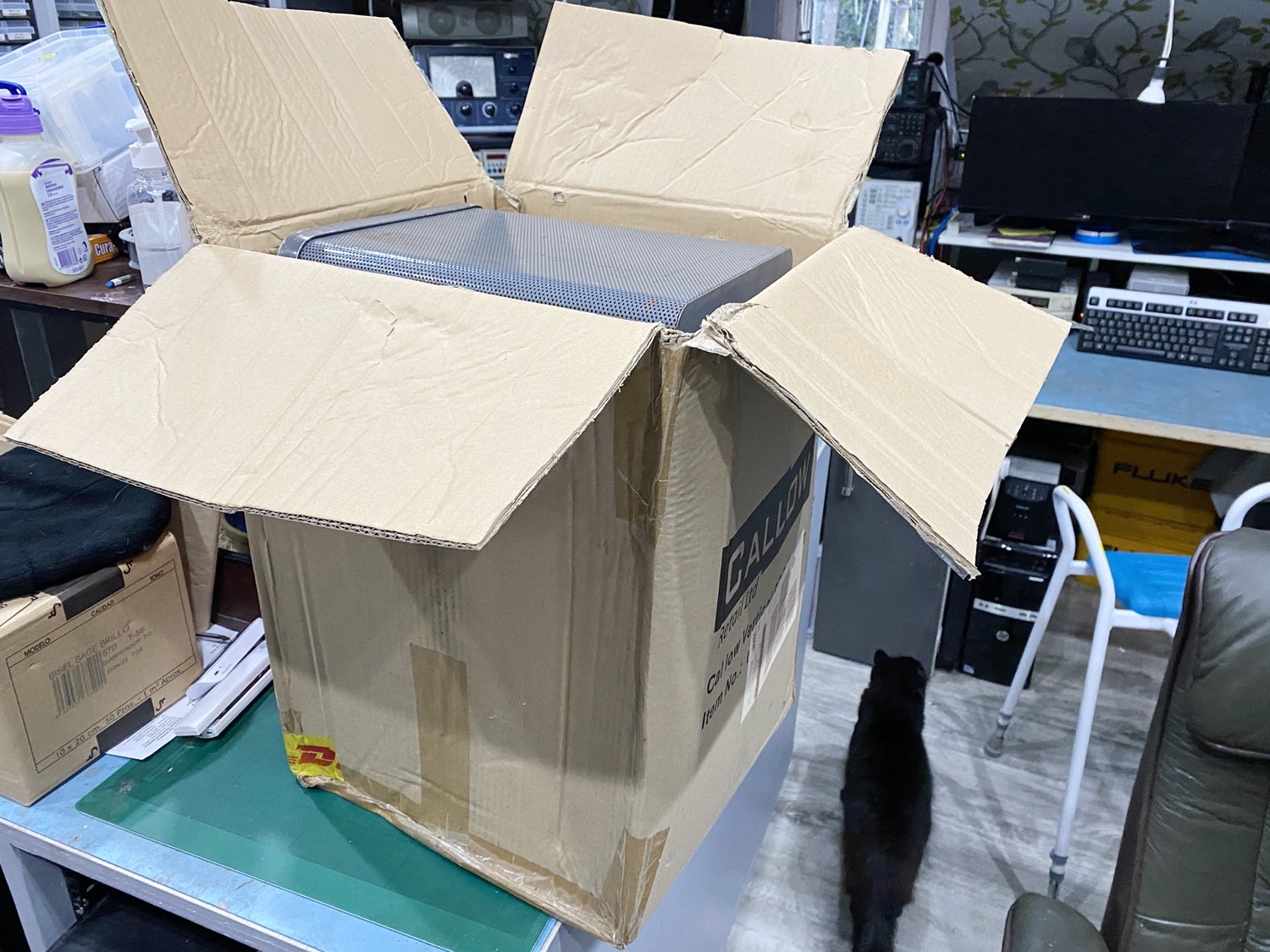
First Look at the Old Boat Anchor.
Now for a Good look around this old Receiver.
The Old Boat Anchor was plonked on the Lazy Susan and given a quick once over to see what was ahead of me.
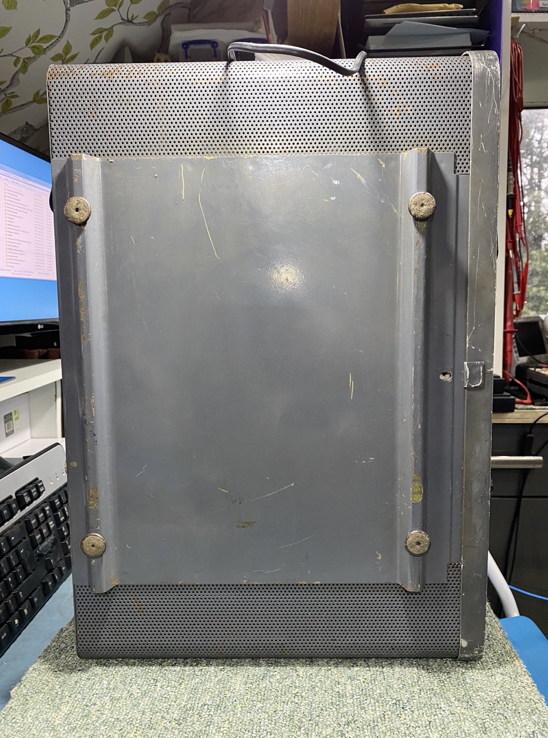
The Underside looks OKay.
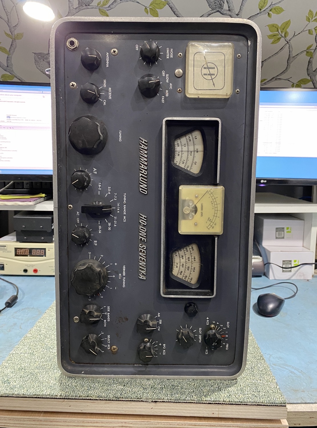
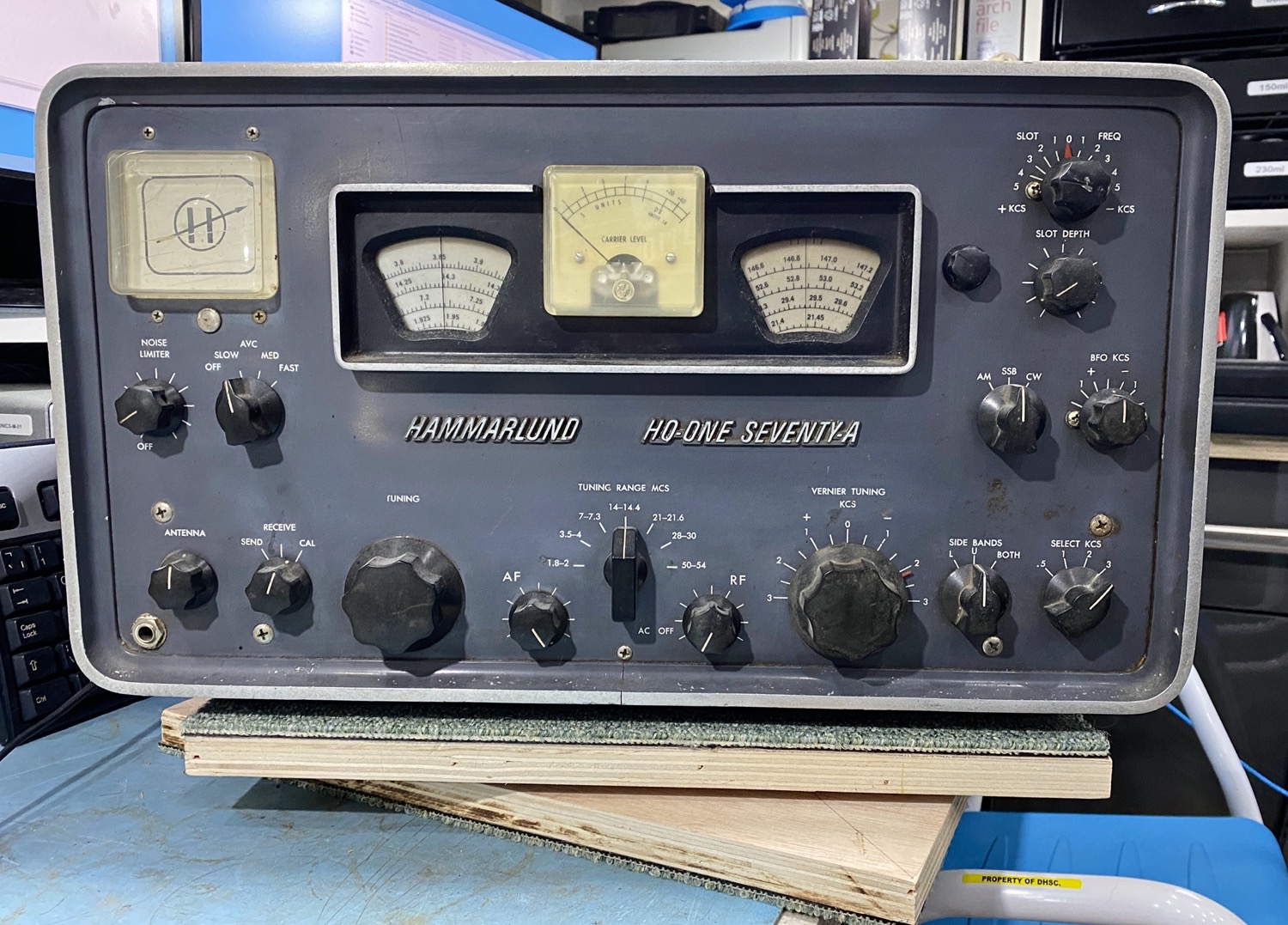
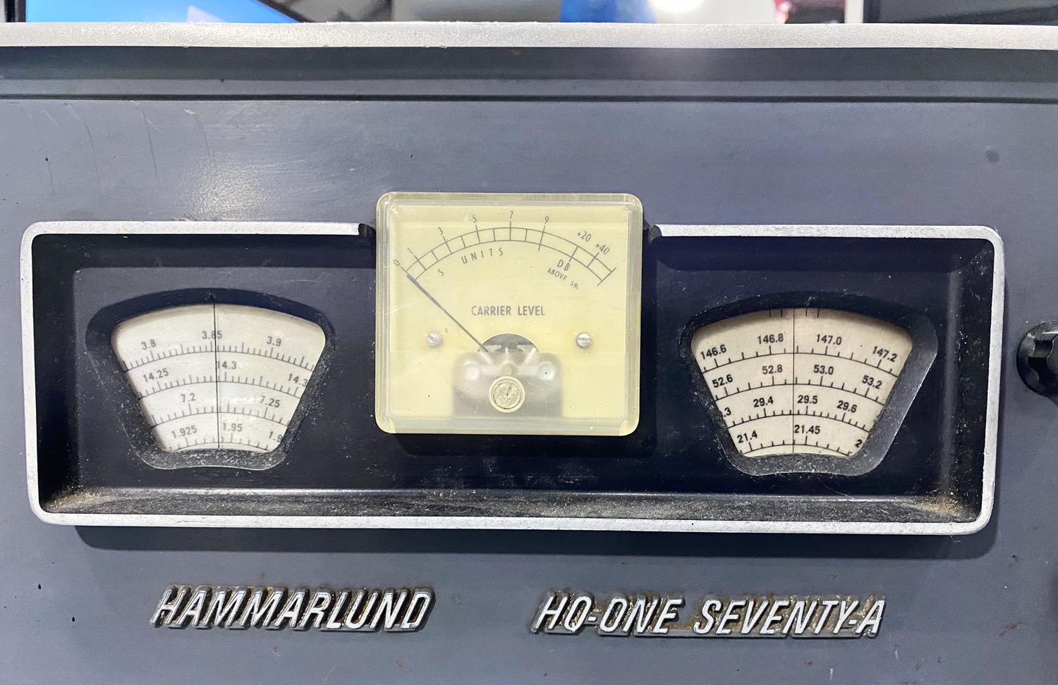
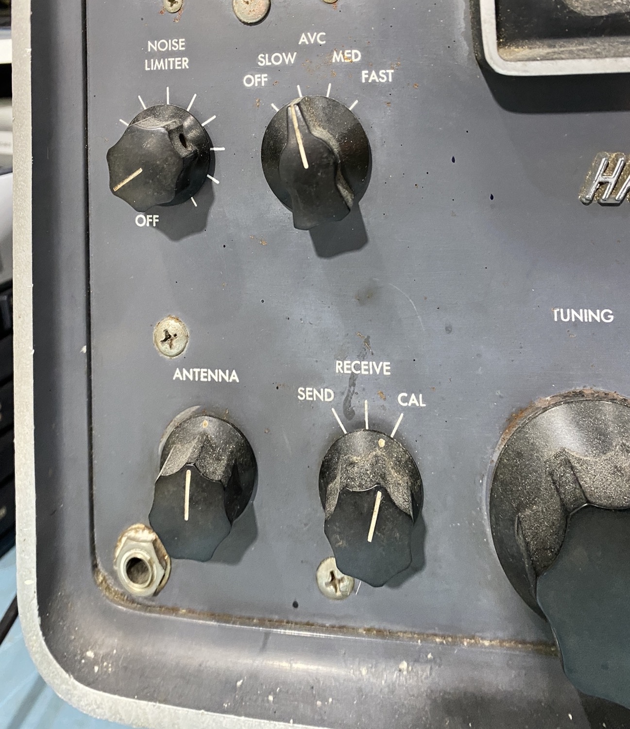
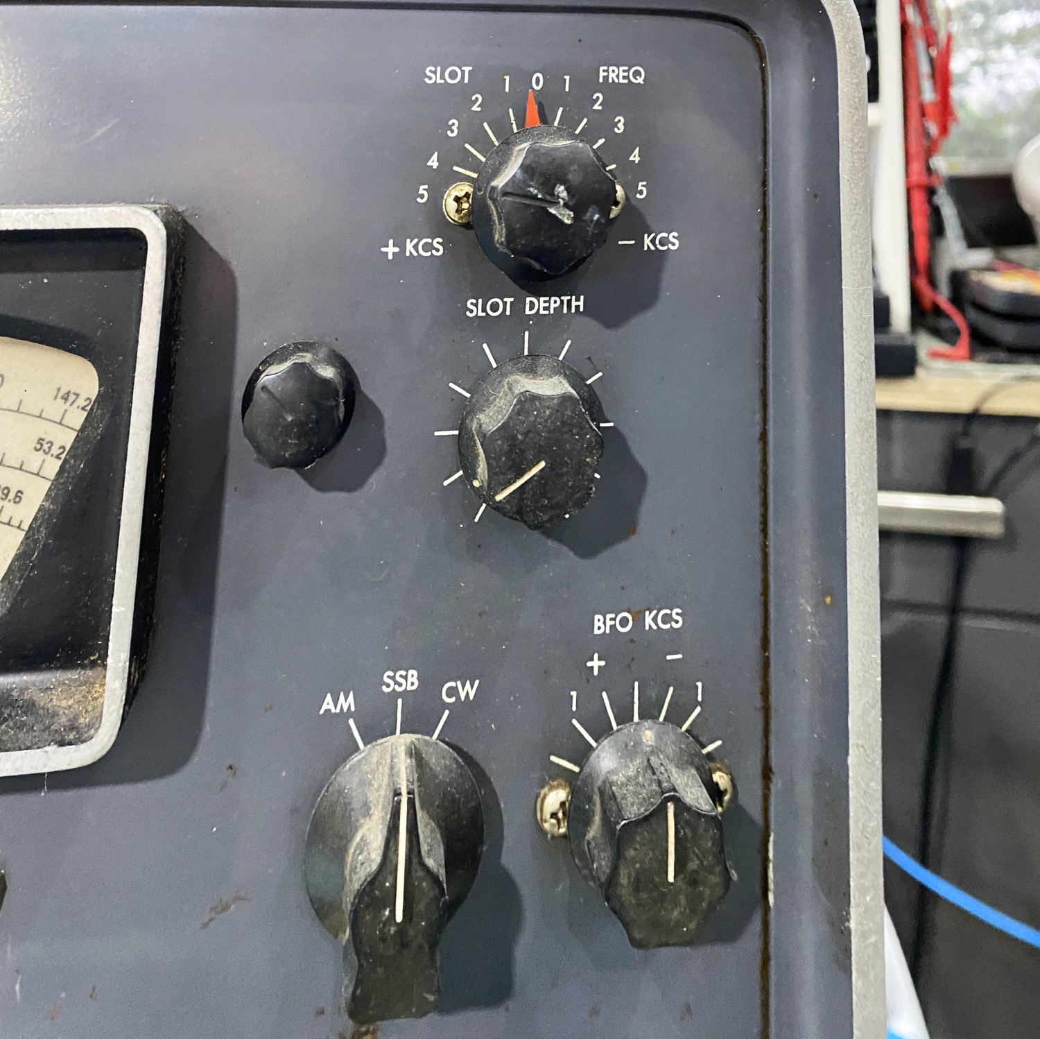
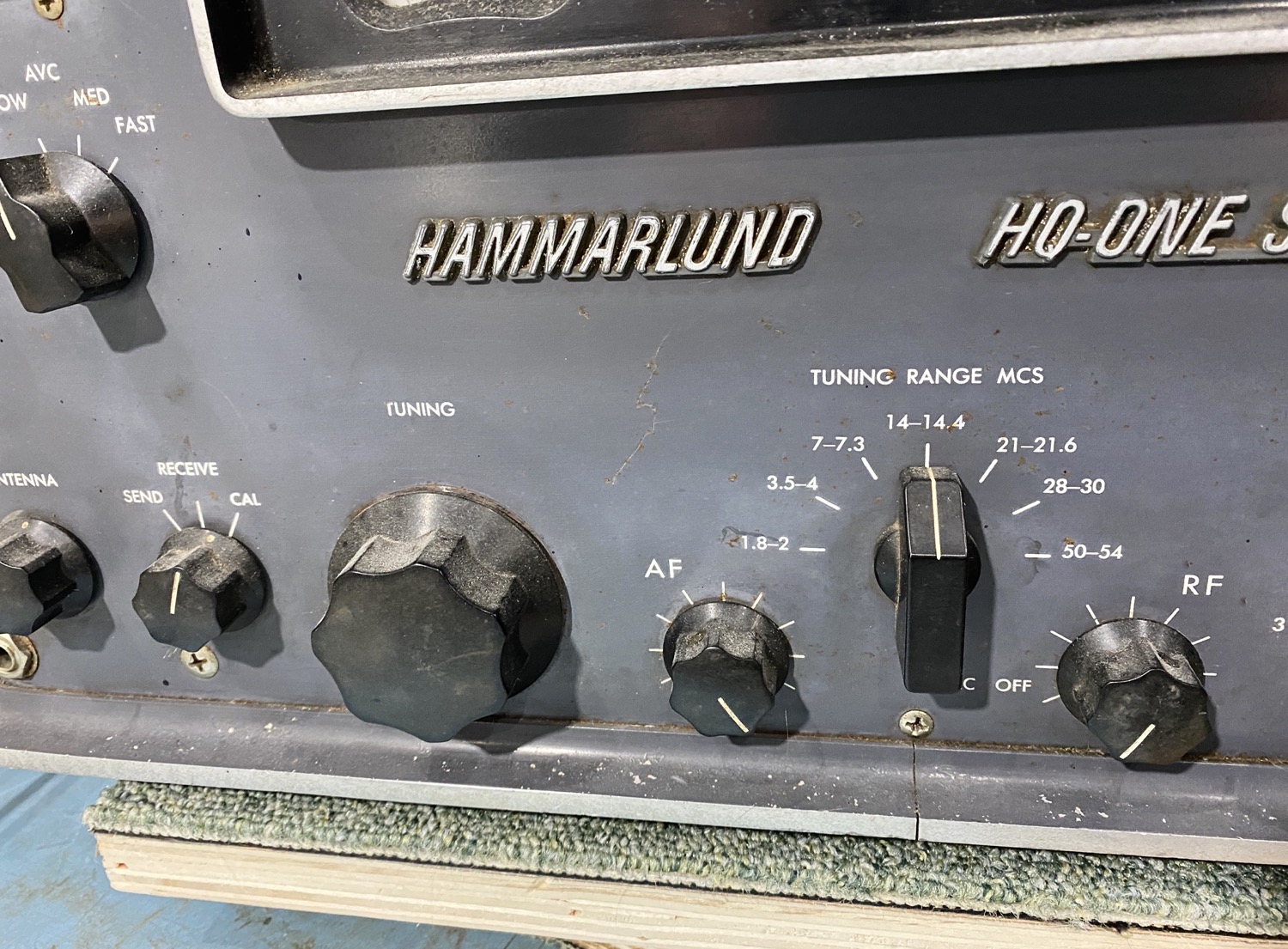
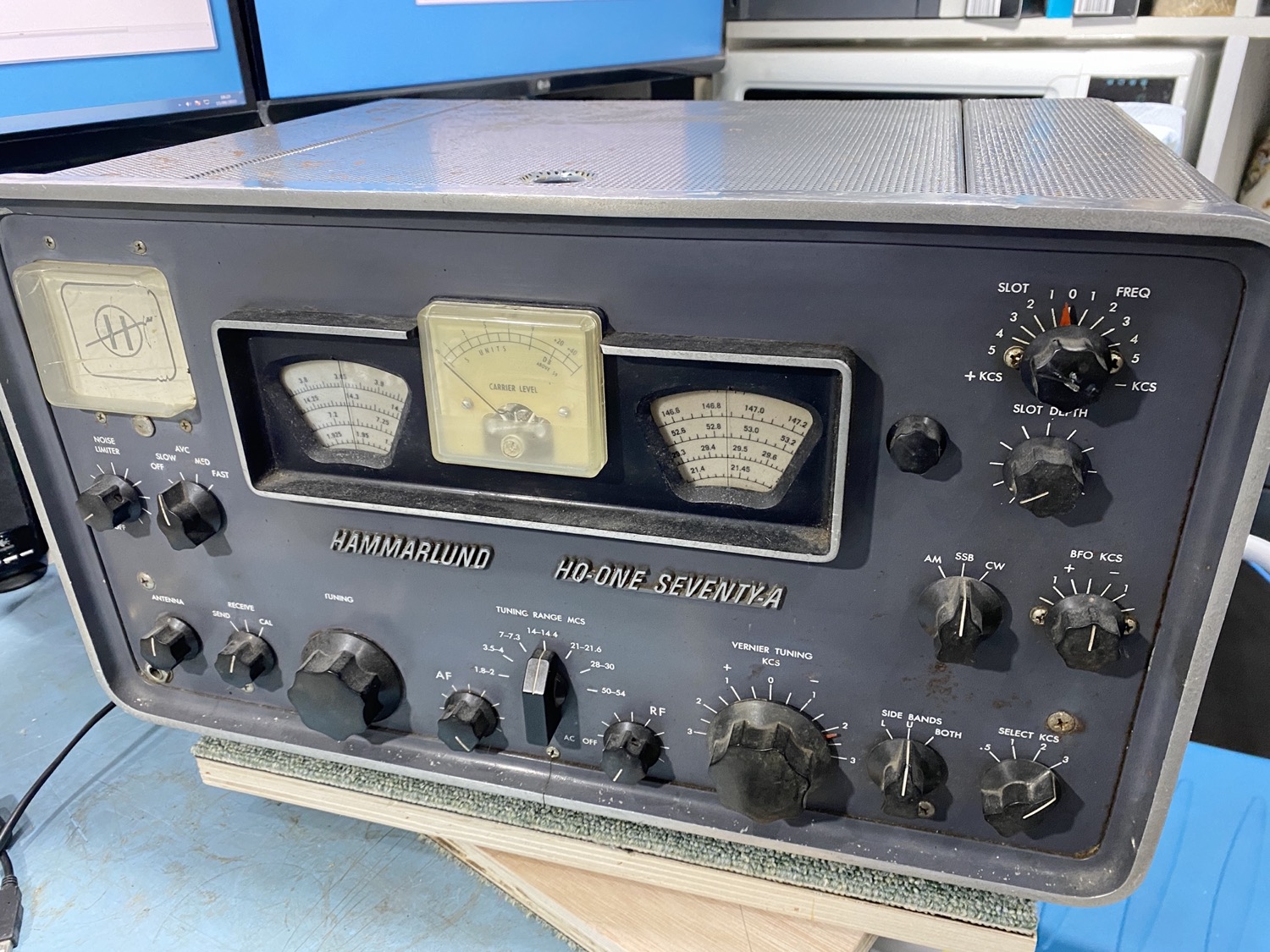
My First Good Look at the Front Panel.
She is far from Mint but I think she is lovely and worth looking after, she was thankfully not kept in an old shed or cold attic, but a temperatures controlled environment so she has been kind of well cared for, and she looks that she has had a hard early life, and what do you expect, it is an old Boat anchor and most of these get sadly thrown out these days, thankfully this one had made it’s way to me so it will get a little care from now on till I leave the planet, I just hope that I can stay here for that long.
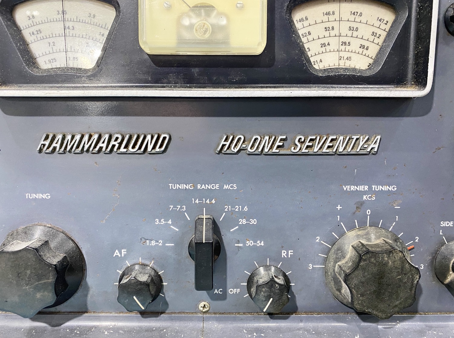
I have only given it a quick look, but it looks as though I do not have to get any replacement knobs at this stage, which is a big bonus, I still have a couple of old radios that are waiting on such items after 10 years of waiting for these items to appear on eBay, etc.
She is a little tatty, but beautiful, I have seen a lot worse.
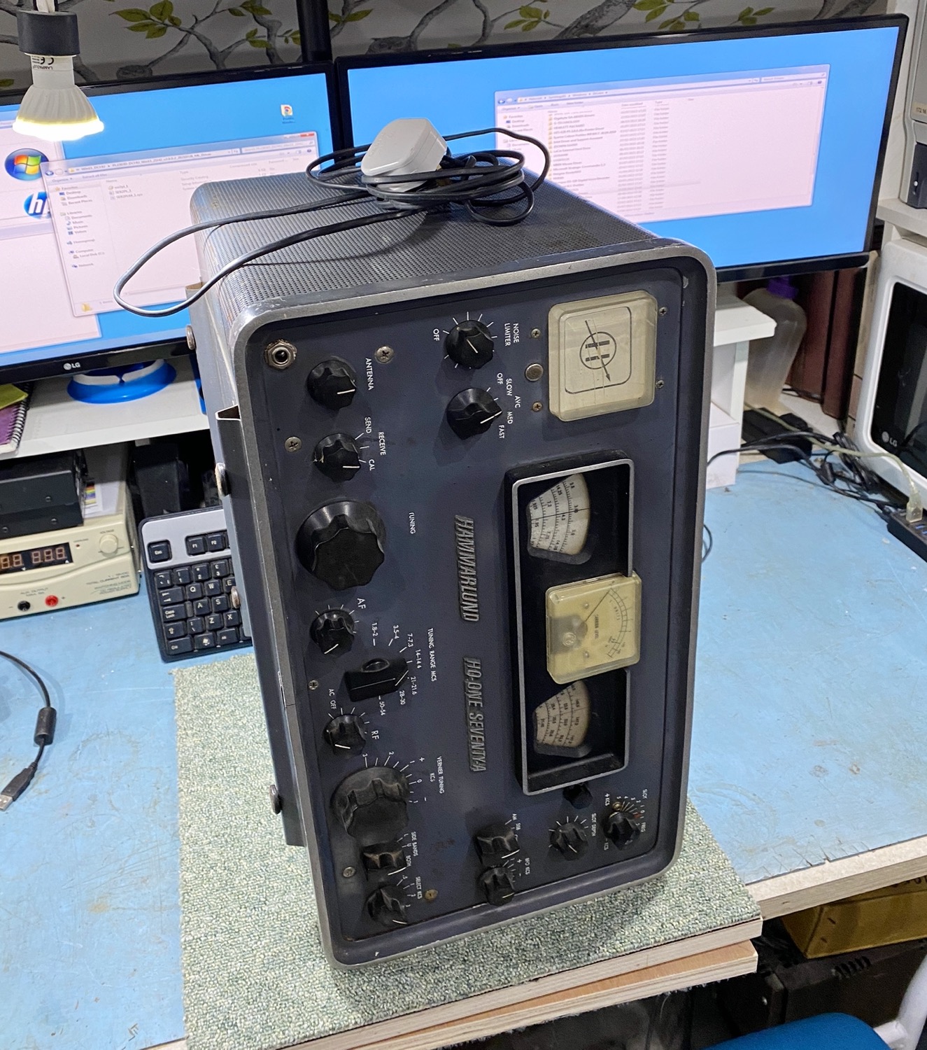
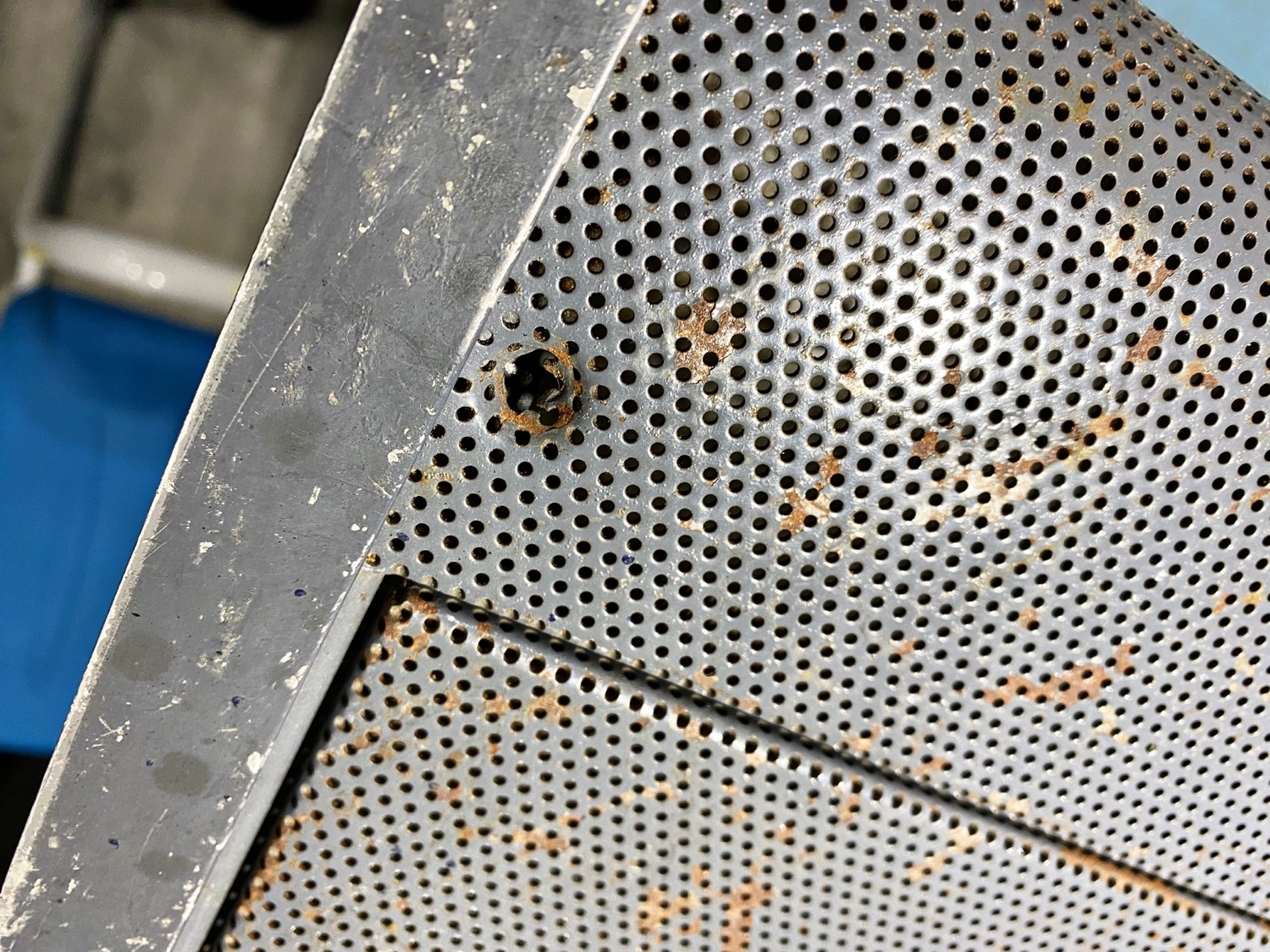
I then gave it a quick look over the outside, there are some holes where some items may have been installed in the past, or where there might have been options waiting to be installed to.
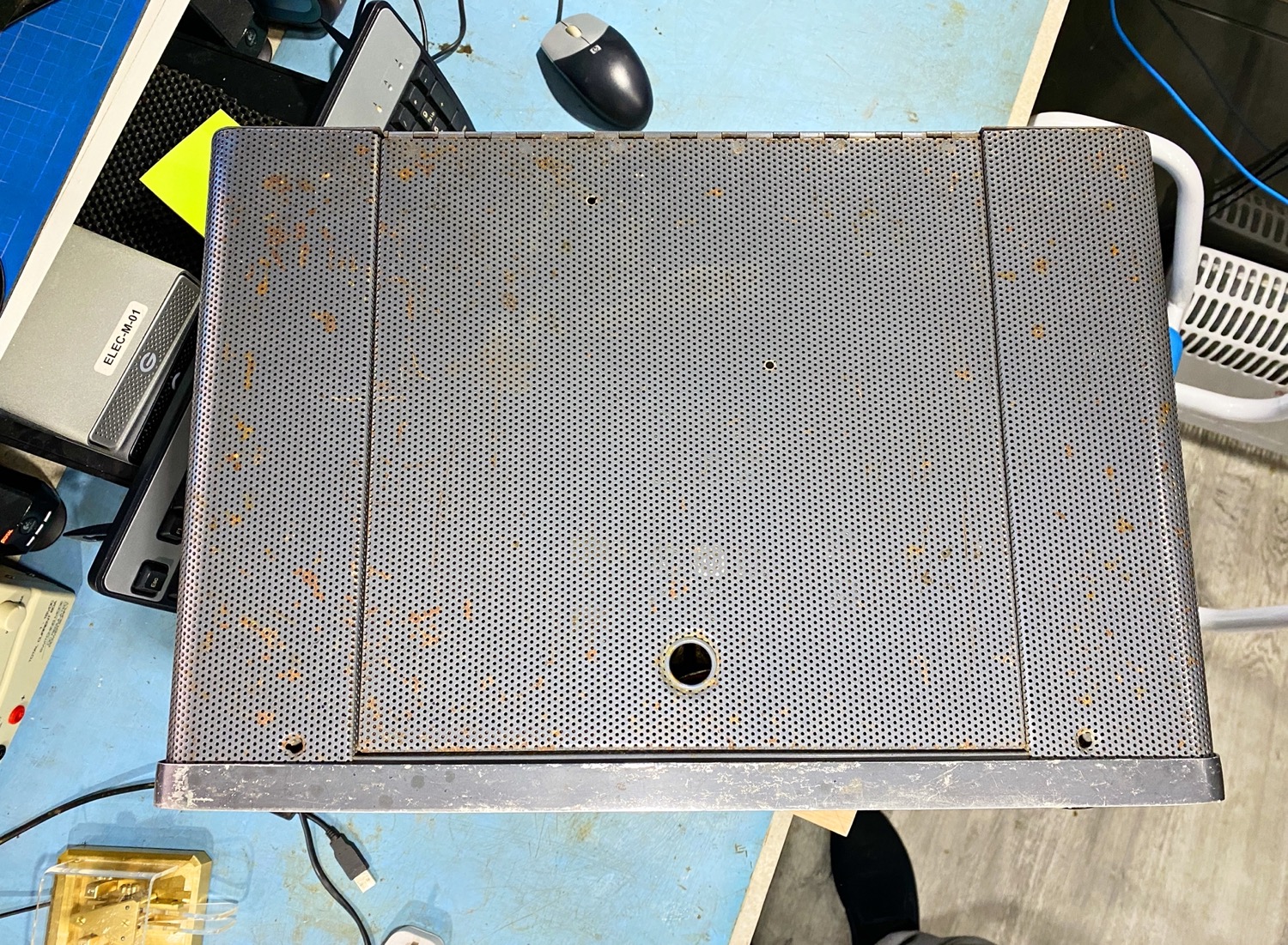
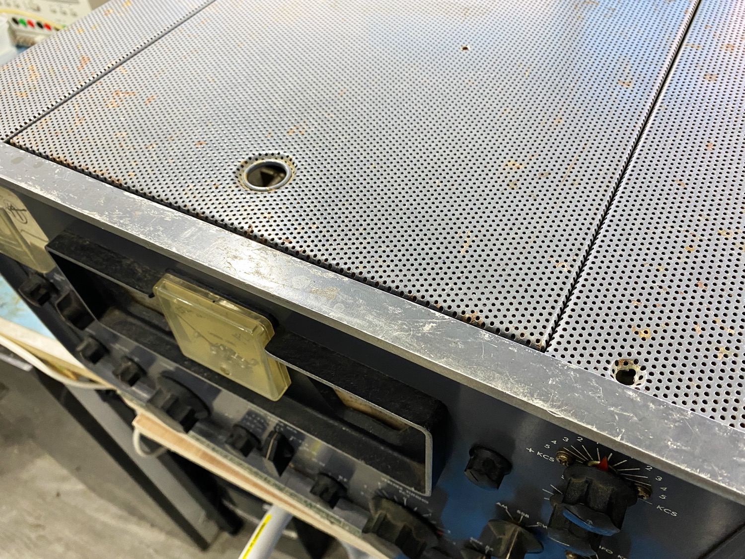
The Top Panel.
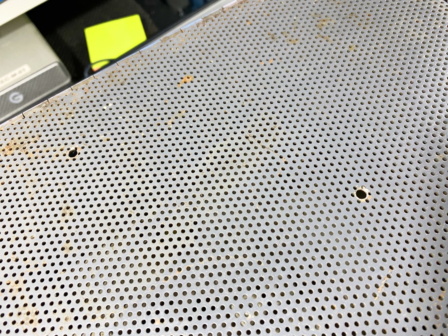
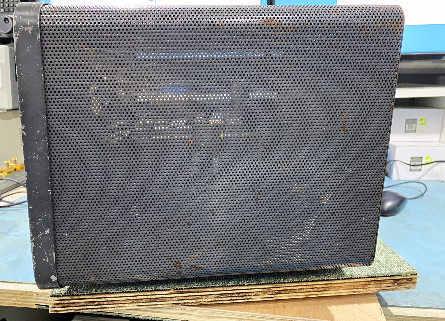
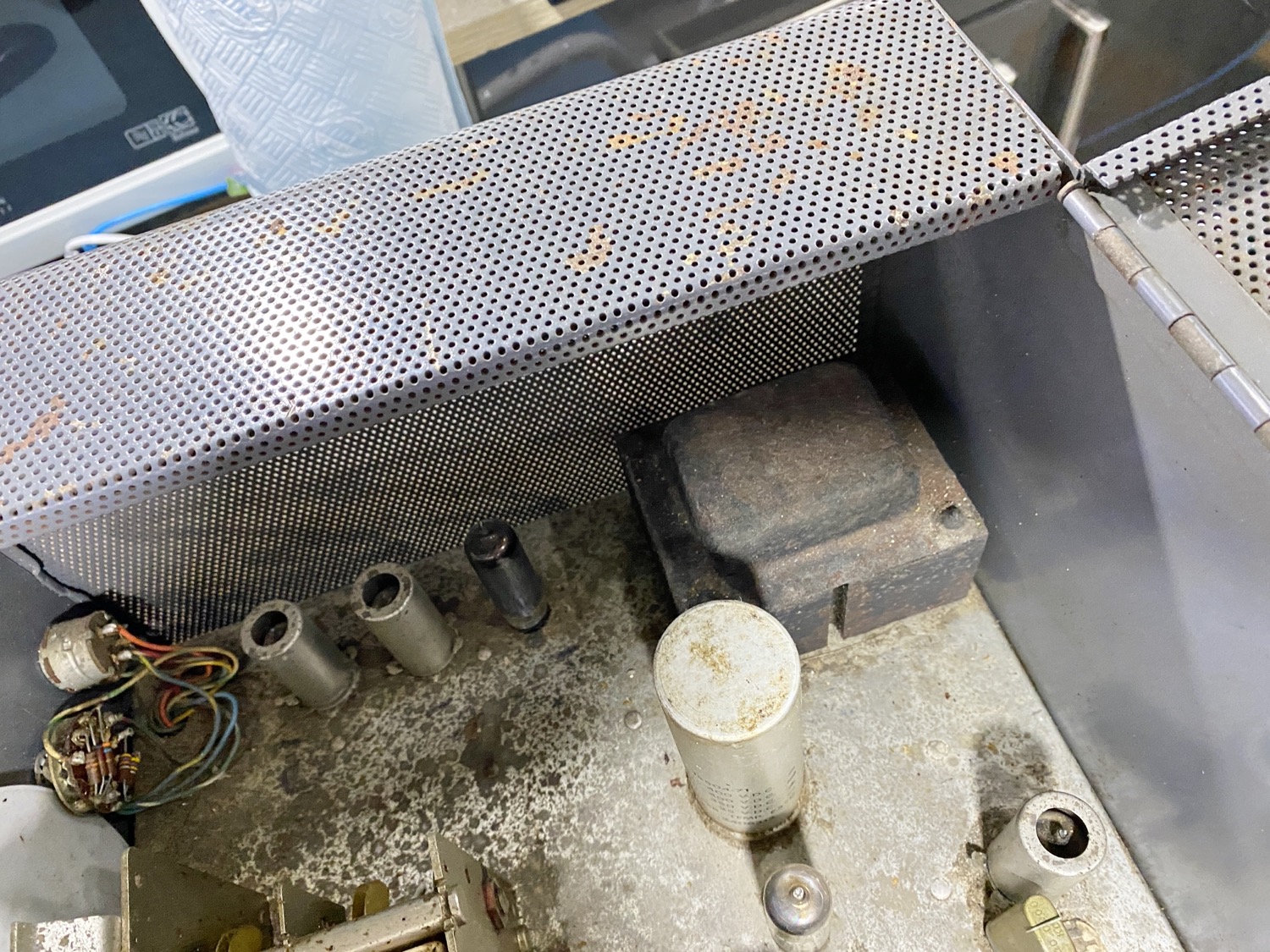
Possibly Holes for an Internal Speaker to be installed.
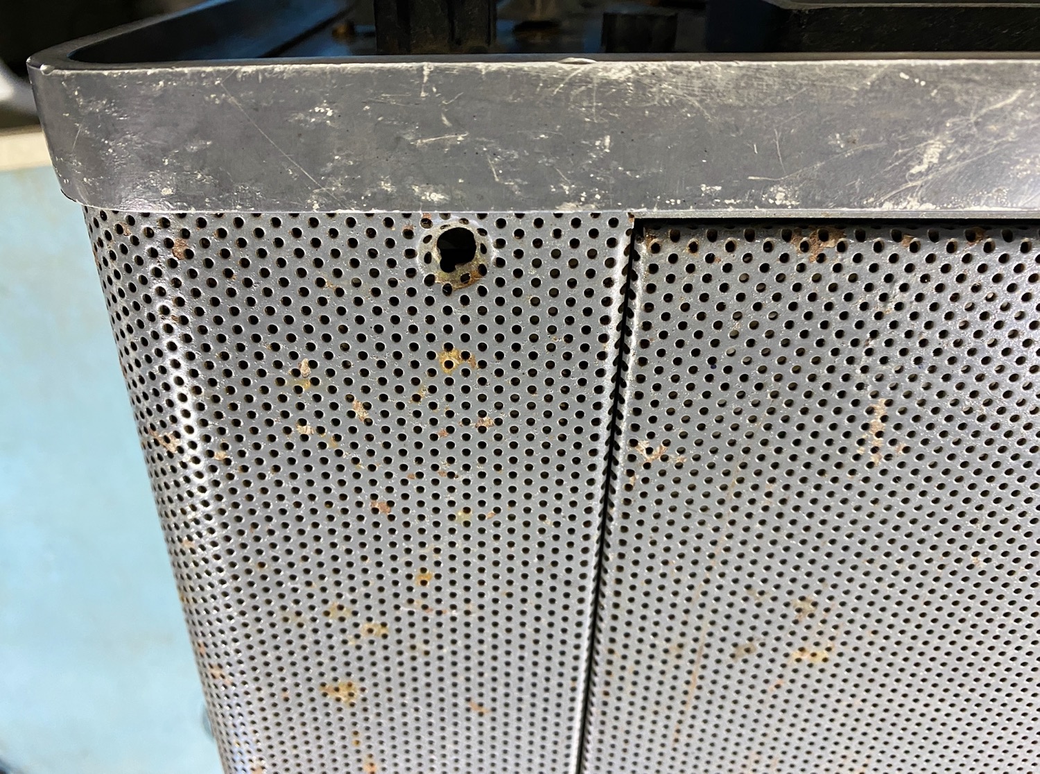
Either side of the lid opening are holes where something was possibly installed to.
There is a bit of spraying to be done.
Both Sides are understandably showing signs of wear.
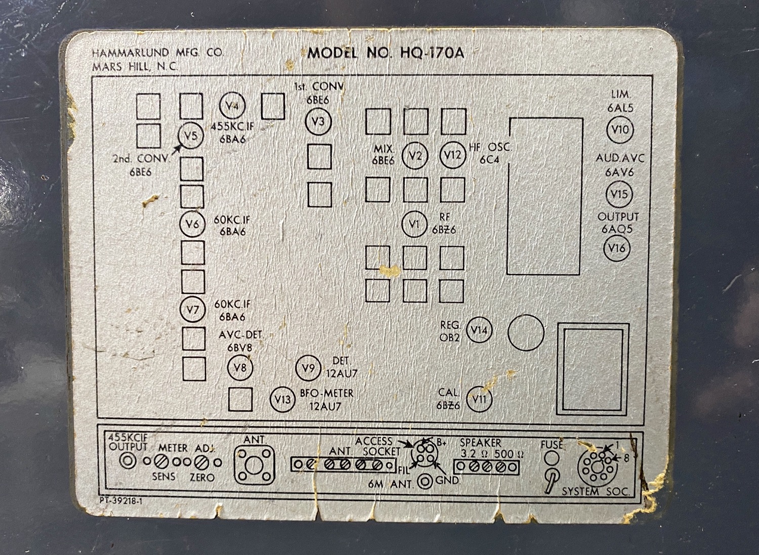
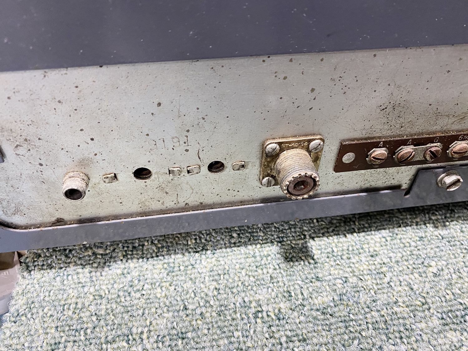
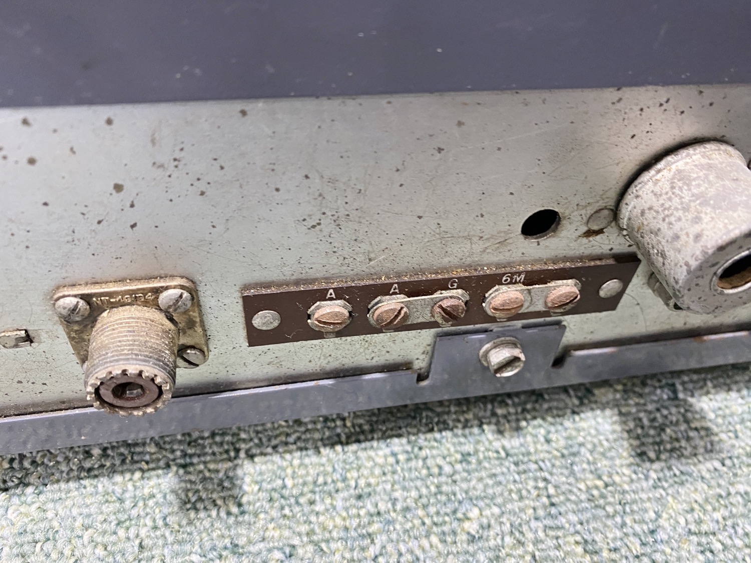
The diagram stuck on the back is fairly intact.
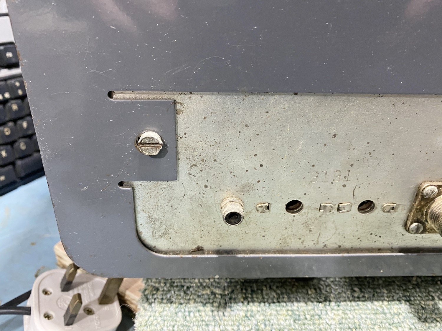
I will need to check in the manual but on the far right of the rear panel there is a Voltage Selector which is possibly missing a plug that would select either 120v or 240v.
From the look at the two old screws that hold the chassis in place, it looks as though it has not been played with too much.
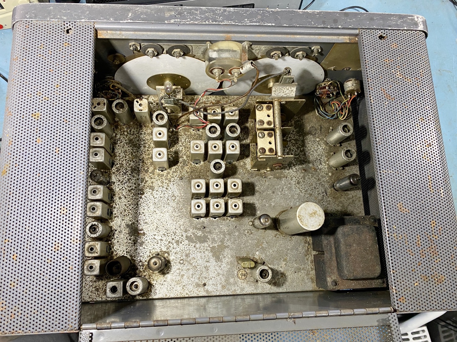
The first look at the guts of the receiver.
The insides of the receiver first look as if it could do with a good clean, the chassis is pitted and possibly a little rusty in places, but far from a right-off, it could be as simple as a quick ‘Bead-Blast’ and a polish which will save around £500 which is the cost of a new replacement chassis.
A Closer Look and it is really looking good.
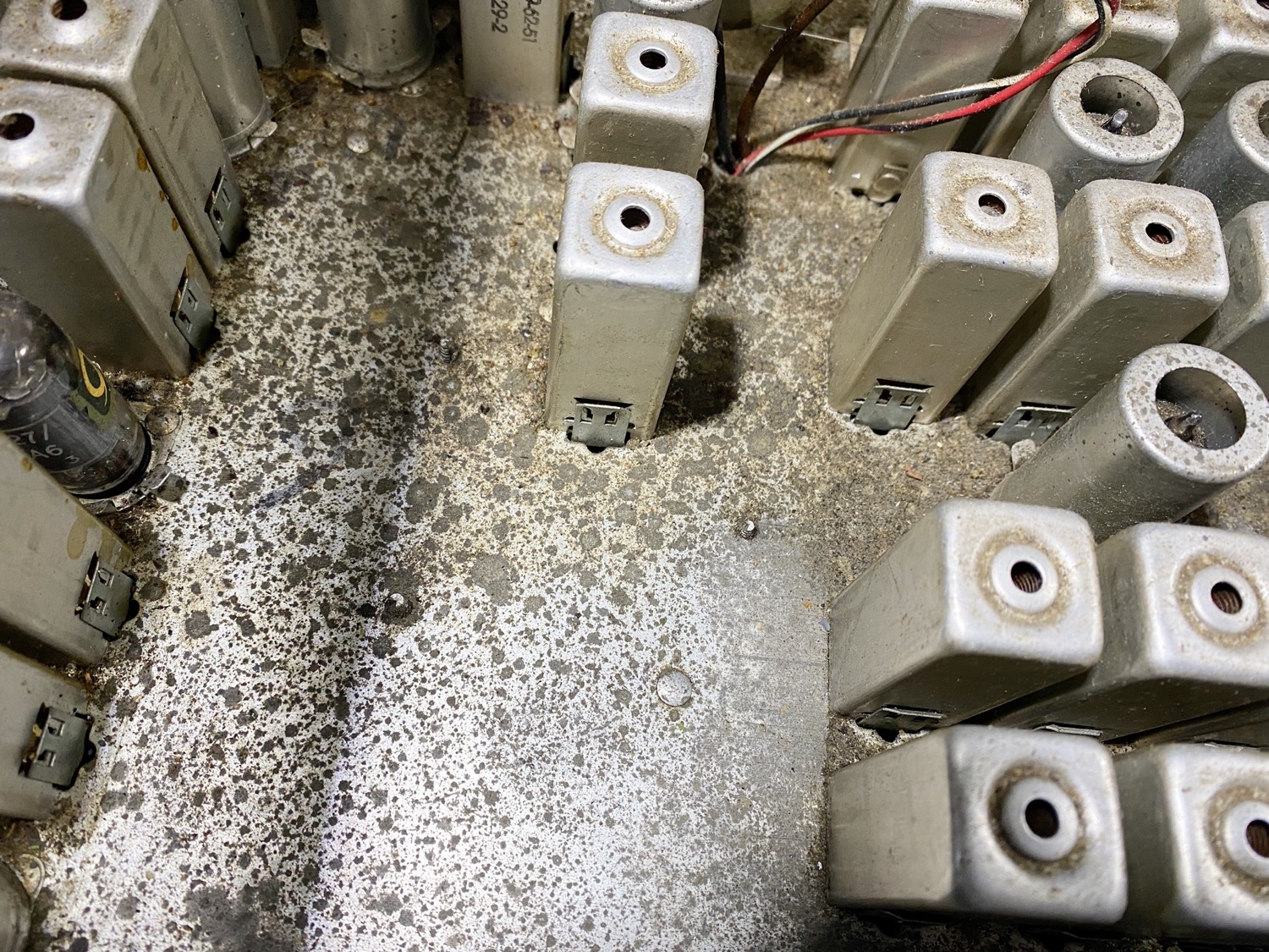
The Top of the Chassis is generally looking as though it really just needs a good clean.
I am only giving it a passing glance to see if anything is missing such as a bulb here and there but it is looking very good and generally a good clean and a polish may get this baby as near to running, I have not looked at the bottom of the chassis of course which is where I expect quite a few items will need to be replaced such as the dreaded ‘Capacitors’.
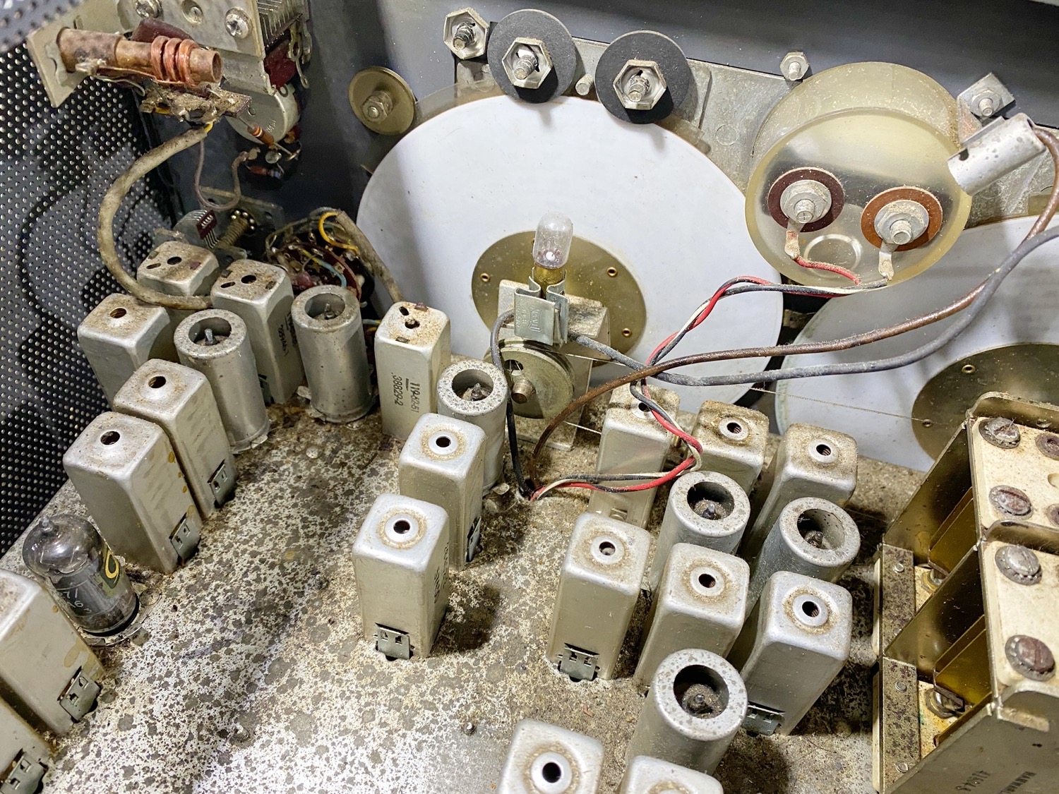
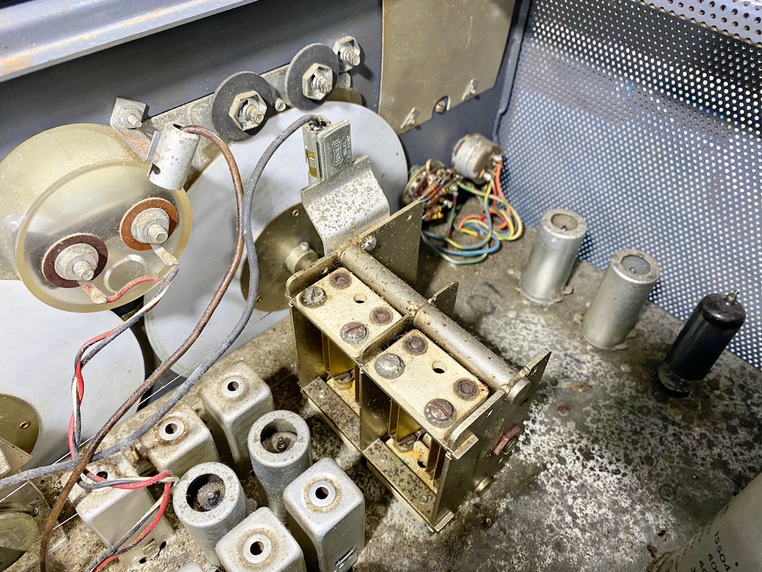
At first glance I am very happy.
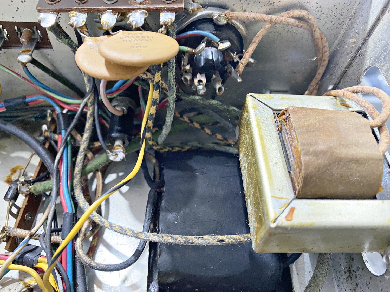
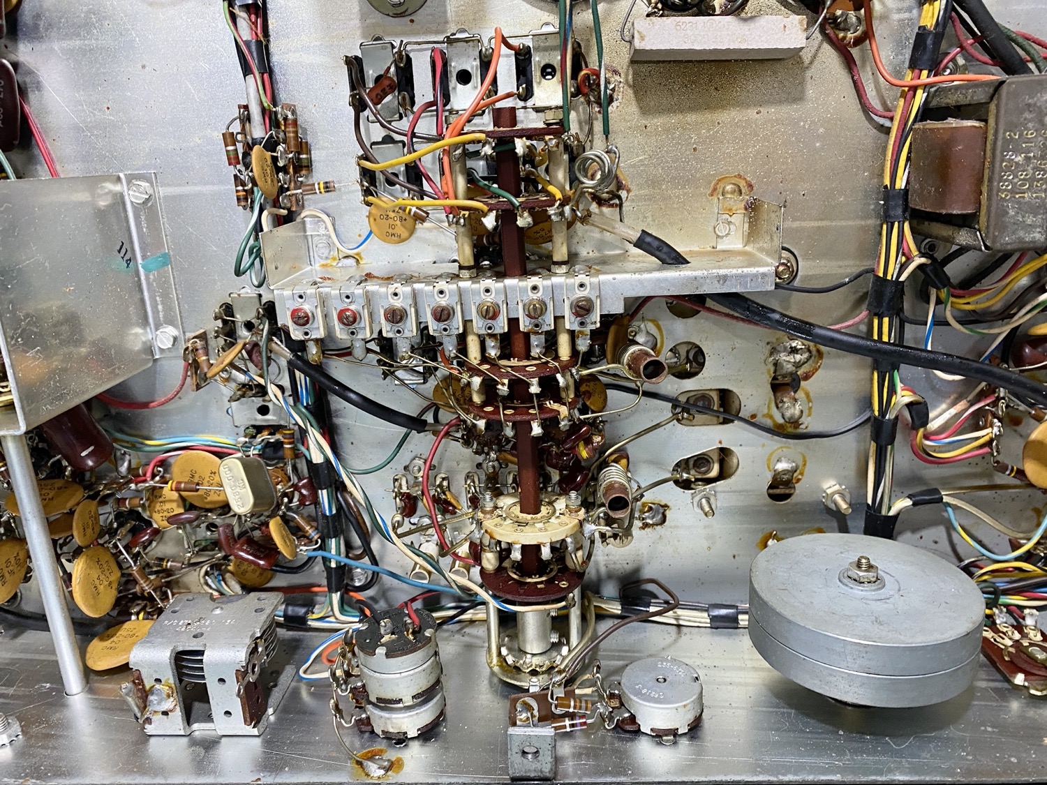
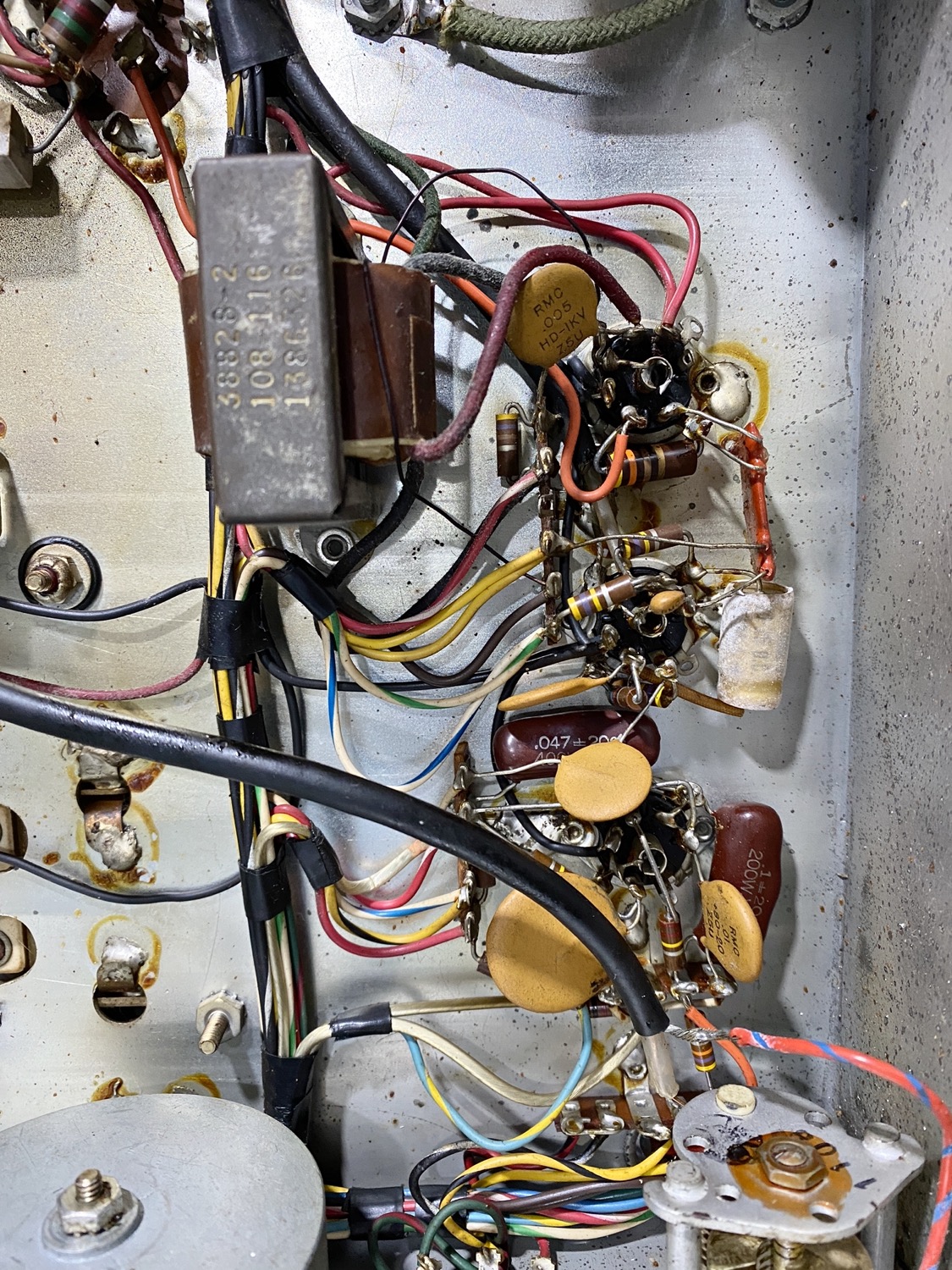
Another thing that I will need to check over is all the cores inside of the square cans, hopefully they are all intact and have not been damaged., there are a lot of Paper Capacitors on the underside of the chassis, there are some very useful video’s that I came across by an American Radio Ham under the name of Charles Smith (KV4JT) which are well worth checking out.
A Closeup of the top of the chassis looks very good actually, it is appearing slightly pitted, but I cannot see any rust spots at all.
I will take a look at the bottom of the chassis soon, please bear with me, I am getting very tired lately from this bloody cancer, but I will update this page soon.
Let's Open Her Up...
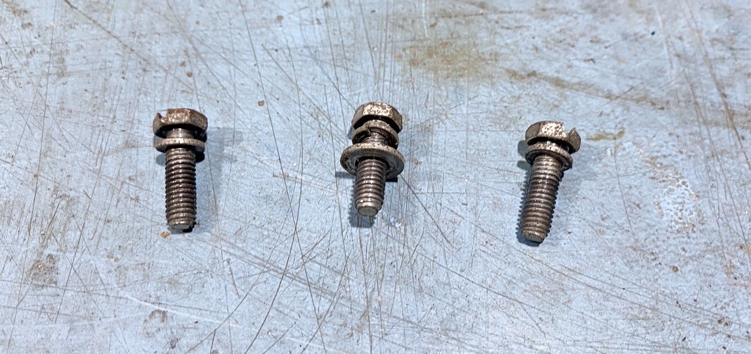
As far as getting into the receiver, it was just as simple case of tacking out the three screws on the back, for some reason the middle screw had an extra washer on it, the holes in the back of the out-case are the same size and yet only this middle screw has a washer on it, just wondered why?
The Three Screws that Hold the Outer Case in Place.
Removing the Outer Case was just a simple case of removing the three screws and being careful with the mains wire.
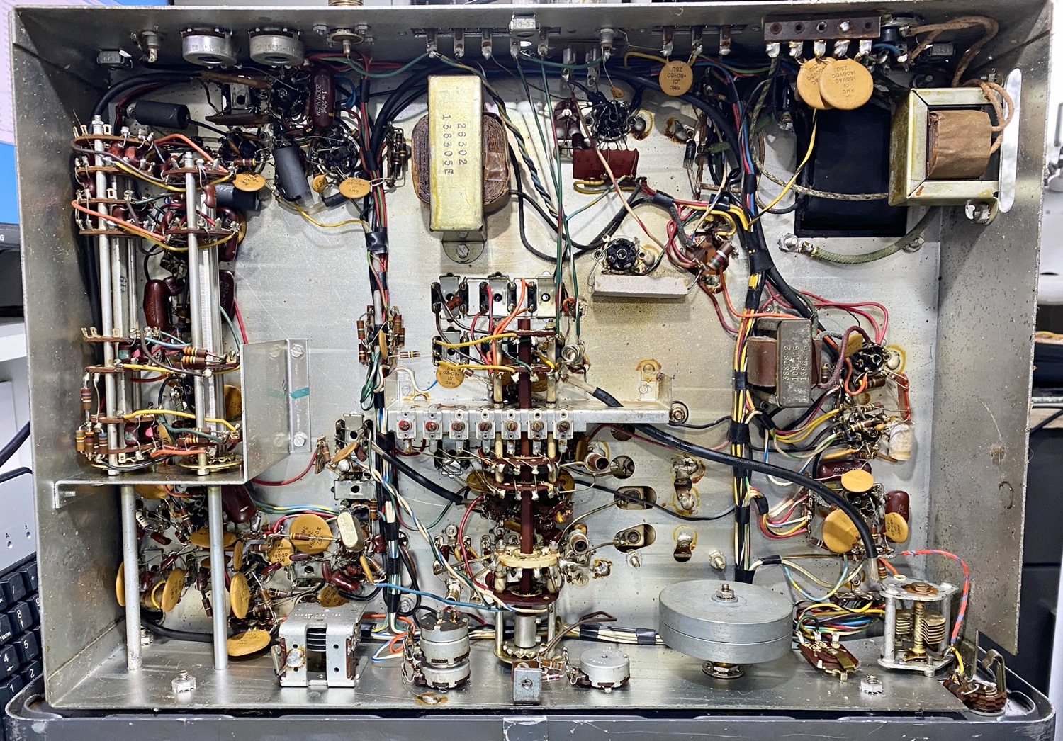
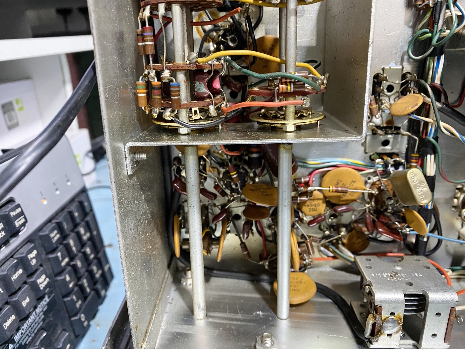
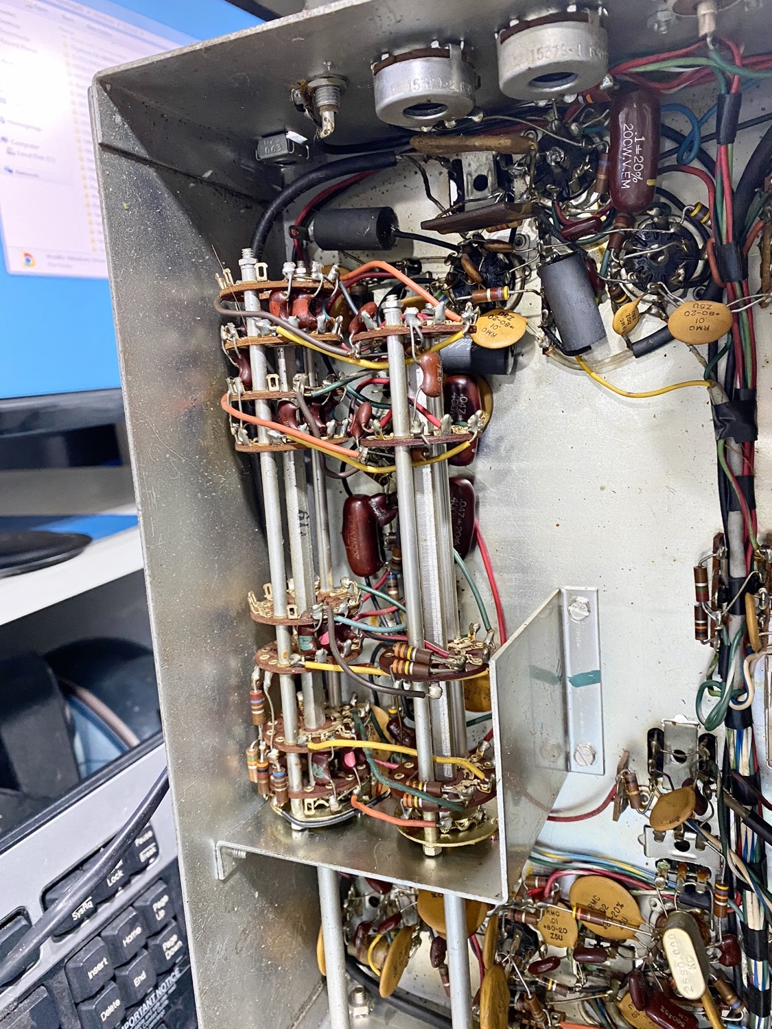
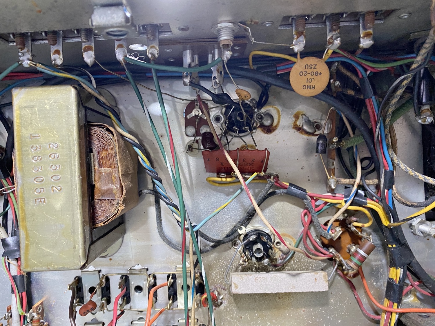
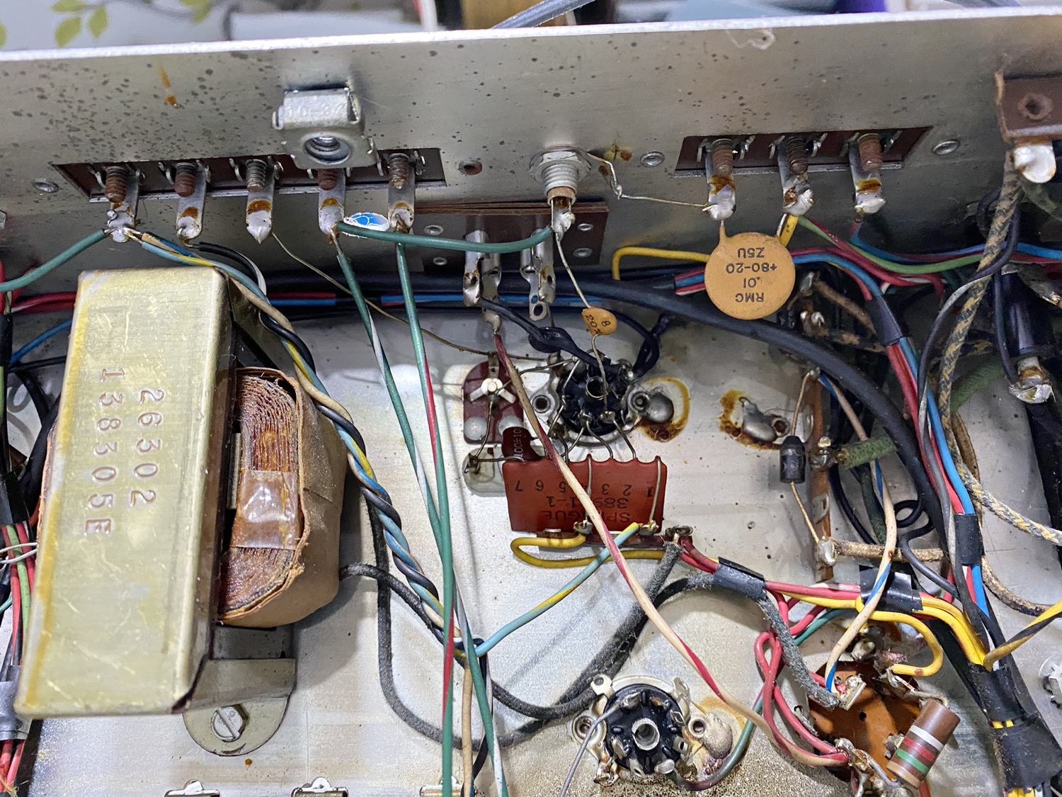
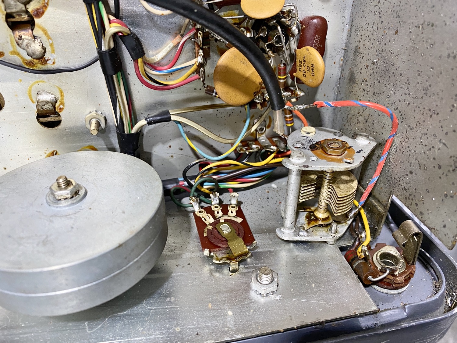
The Underside of the HQ-170A.
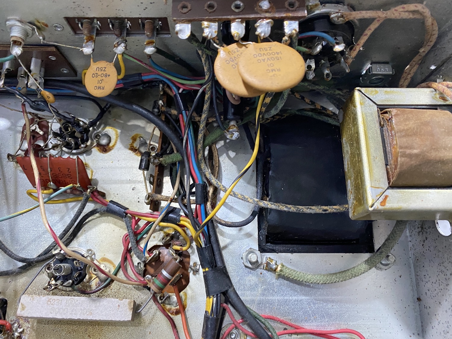
Once I could re-arrange the chassis on to the lazy Susan and get my first glimpse of the underneath of the chassis I was really surprised to see the difference between the underside and he top which is open to the air, this could possibly make the restoration a lot easier to do, here are a few photos so that you can see the condition of the underside.
Now I really need to look at what is the best way to proceed here, I was just going to break this down like I have done in the past with a lot of the KW Radios so that all I am left with is the chassis which would make it easier to clean and polish but it takes a lot of time de-soldering, unscrewing, and removing all the parts. I am sure that I will still have to check and remove most of the known bad capacitors, I do not think it is worth me making this a true solid state receiver by replacing all of the vacuum tubes with transistor’s, I would prefer to keep this as original as possible.
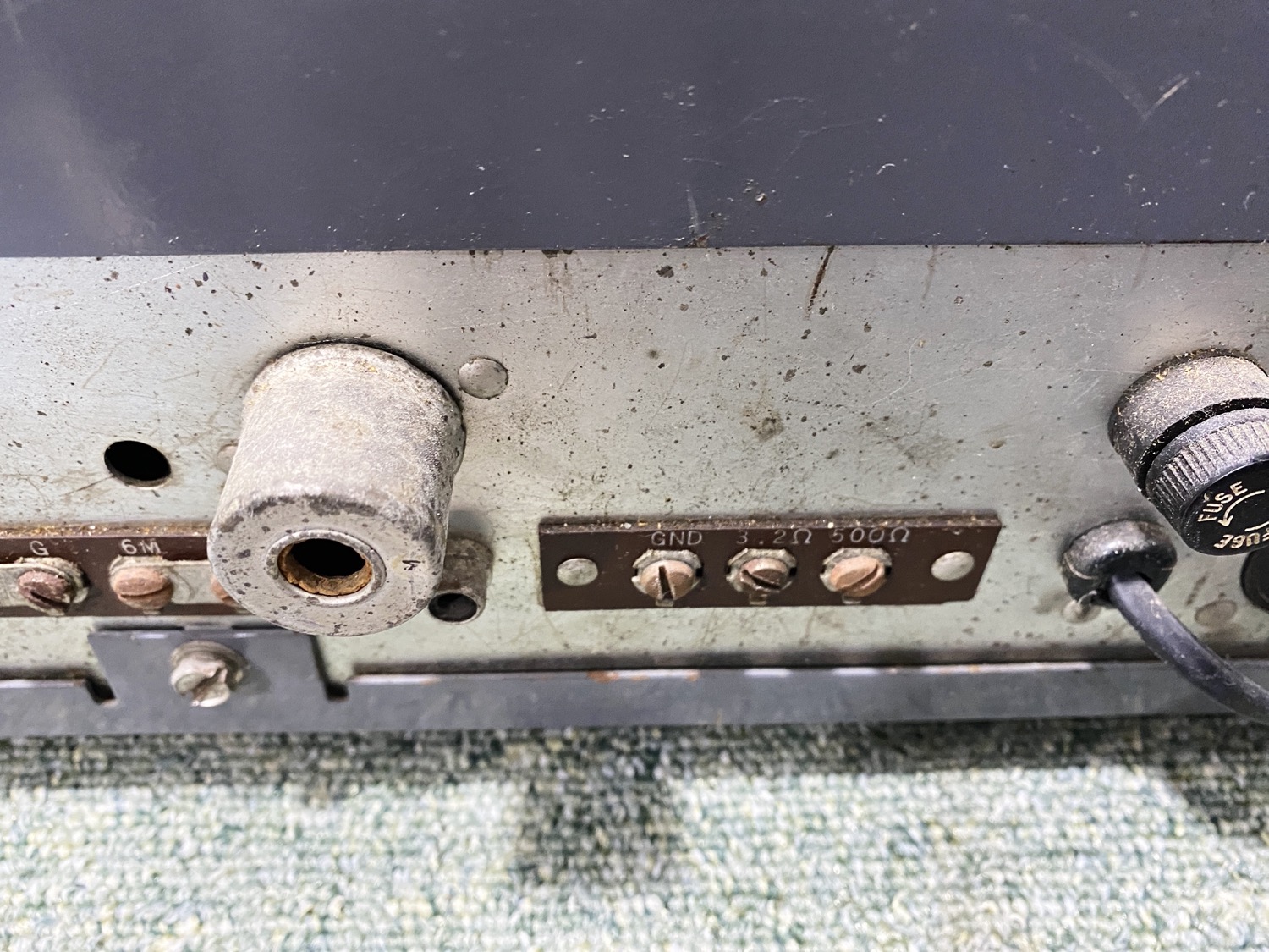
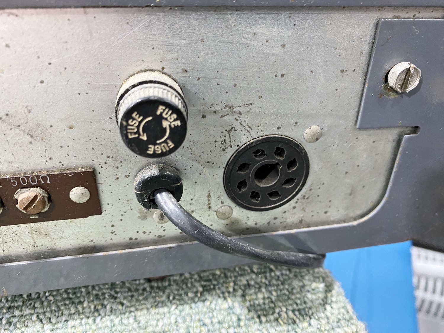
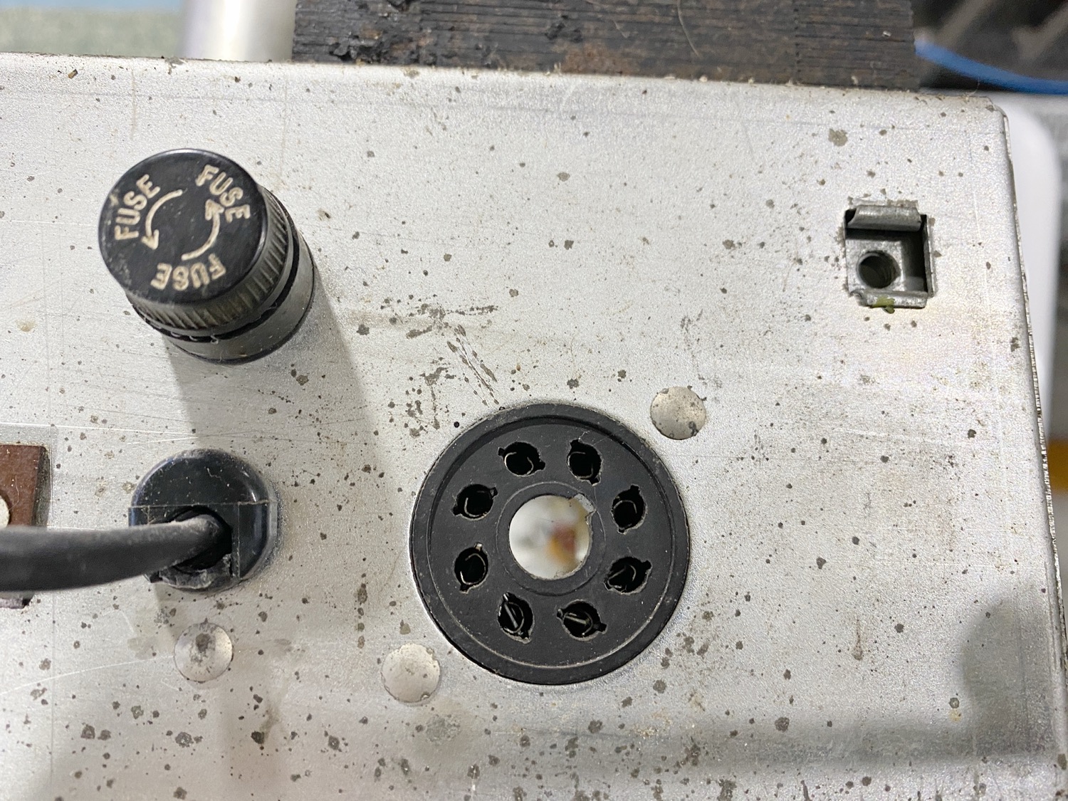
The Voltage Selection Socket with a missing plug??
The Rear of the Voltage Selector.
The Voltage Selection is ‘Still’ giving me a little stress t present, trying to locate a good copy of the schematic is proving to be a challenge, the unit came with it’s original ‘Hammarlund Power Cord’ which is a 2 wire cord and is obviously old, I should replace this as it is older than me, my worry here is that even though it has this old cord, it also has a UK mains plug on the end, maybe I am just over thinking this at the moment, but you will understand why I am a little worried about this empty voltage selection socket.
Lets do something Silly...
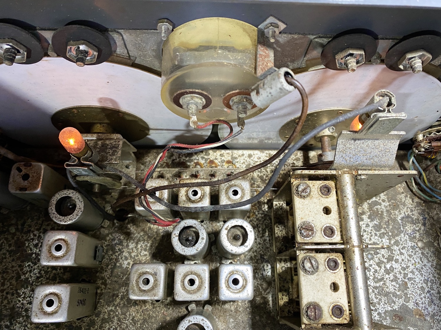
After seeing the underside of the chassis, I took a bit of a punt and decided to see if I could warm her up. With a missing speaker I knew that I would not get any sound out of the unit, but at this stage I was not really after listening to the audio, I was just wanting to see if it would light up a few bulbs and see if the meter would show a little movement, from the look at the top side I do have a valve that has a totally black glass on it so I bet it will need to be replaced, and there are a few capacitors and maybe the odd resistor that will need to be checked before I will be totally happy.
That said I am fairly happy to apply some power and warm her up over a few hours whilst connected to a bulb tester and using a variac to bring up the power slowly.
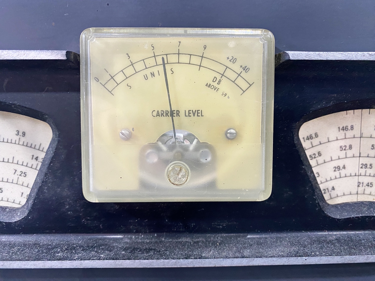
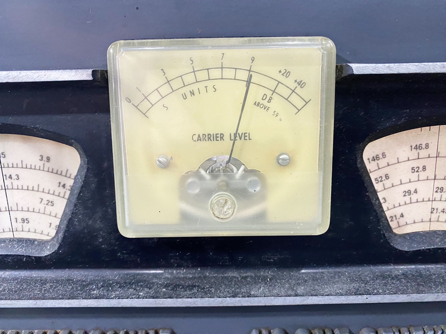
I switched it on and slowly brought the voltage up, after 6 hours I had the voltage up to 60v and I started to see a faint glow in the bulbs and we had a little meter movement, a few more hours later and I was up to 90v, the lamps were now glowing a lot and the meter was practically full swing, so I am wondering here is she is set to 120v?
The Meter at 60v AC Applied.
The Meter at 90v AC Applied.
And at nearly 120v the bulbs look OKay, so is this unit set to 120v with no plug inserted?
So, I am left with a few questions, I brought the AC input voltage up to 120v and left it there for about 4 hours, we sore no smoke and heard no loud noises from exploding capacitors, etc. I decided to leave it here until I can find a good schematic and think about how I am going to clean the top, I will see about a replacement clock for the blank on the front panel, and I will replace the power cord as well. It will be the cleaning that will take a while, in the meantime I will be looking for some good manuals to help me get through this.
Questions So Far
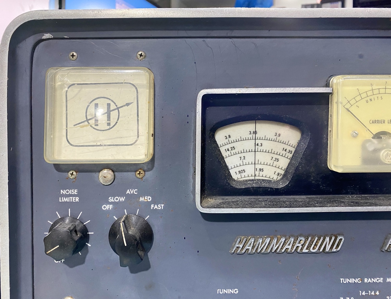
Why is there what I presume after a bit of internet trolling, is a missing clock on the top left of the front panel, It will not hinder the restoration but I think I will have to try and hunt one down.
I Presume there was a speaker fitted to the top of the outer case, if so I need to look for one, this could take a while me thinks.
What are the two holes for at the front of the top cabinet either side of the opening for?
Is there a plug that I need for the voltage selection at the back of the unit.
What Input AC Voltage is this unit set to?
I Need the Paint Code for the Hammarlund Grey so that I can get a rattle can
Hammarlund Paint
It seems that Paint Colours have changed somewhat since I was painting bike, back then it was all millilitres or weight, now it seems to be just the nearest name for the nearest colour scheme, I suppose it’s because I am after a rattle can as opposed to mixing it for spraying.
So all that I need to do now is get a rattle can from MotoWorld and some rust killer, then give this a good but light scuff up and then get the Rust killer on to the small areas and once dried spray up the entire outer case and possible the outer edge of the front panel but I will need to apply some tape first and file down he areas that are rough, hopefully then it should look very nice.
I am now retired and living on the Isle of Man, my background is as varied as it gets, ranging from Information Technology to Graphic Designer and 3D VFX Artist, using and teaching Autodesk Maya, Softimage, and Smoke, one of more enjoyable positions. Since Moving to the Isle of Man I try to keep myself to myself and work on the house, I don't do much with regards to Amateur Radio or Electronics anymore, but I am still interested in the hobby and may well get back into it one day....
