Well, we know that it works, it has been a while stick in a box, in fact I cannot remember just how long, so what could be wrong with this little beast, surely nothing too bad, well early signs are not good, but after a small amount of cleaning we may just have a small and simple restoration, Yeh right! We know how those start.
I cannot remember what the build date of this one was, but it has one of those old foil PCB’s that you know have issues with lifting of the tracks with age, especially if something has been spilt on them, but at this stage I was amazed at just how clean it looked so far.
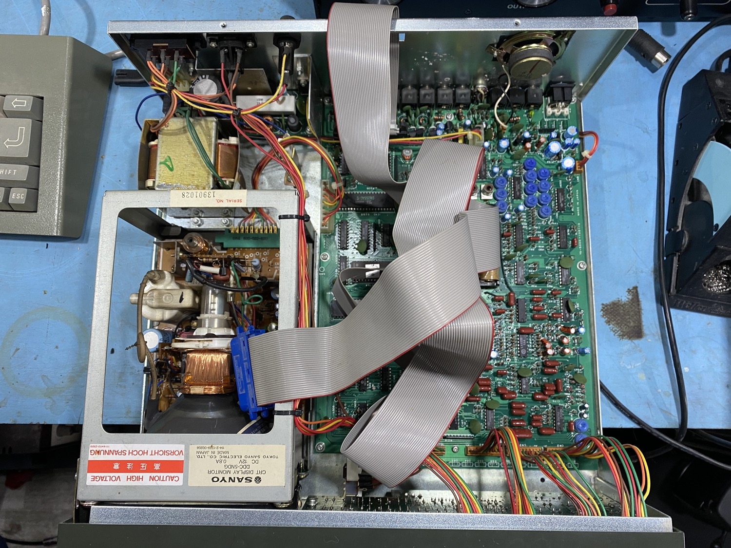
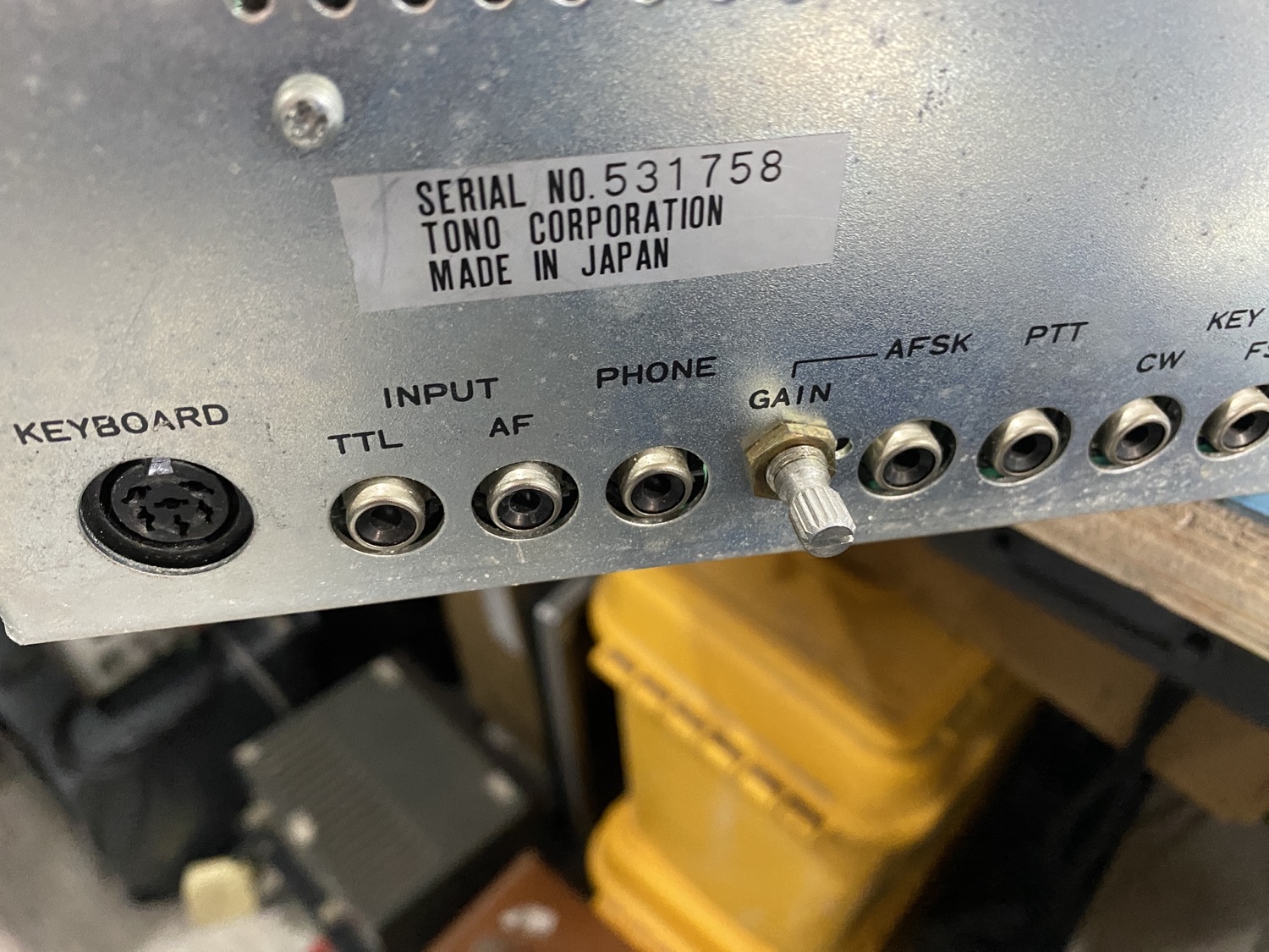
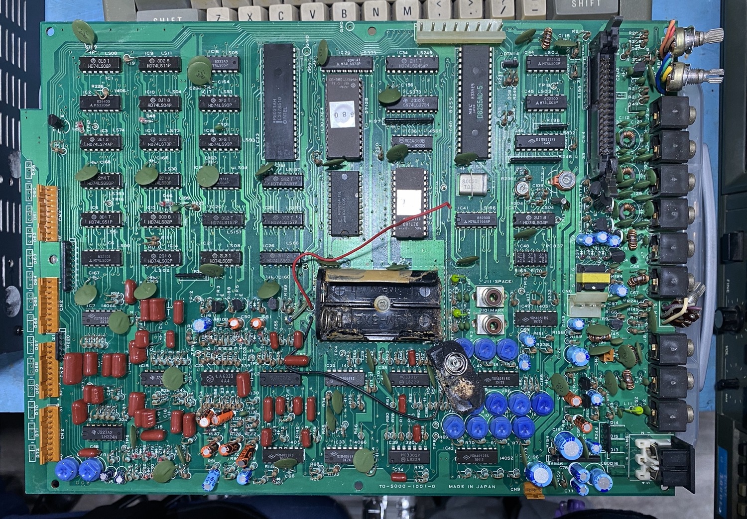
TONA THETA 5000E Sender Reader - First Look with the Lid Off, Inside - So Far So Good.
I did not notice the 'Elephant in the Room' at this point.
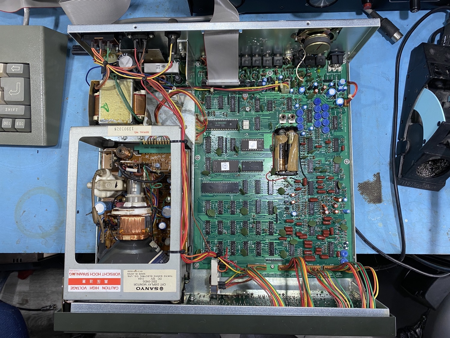
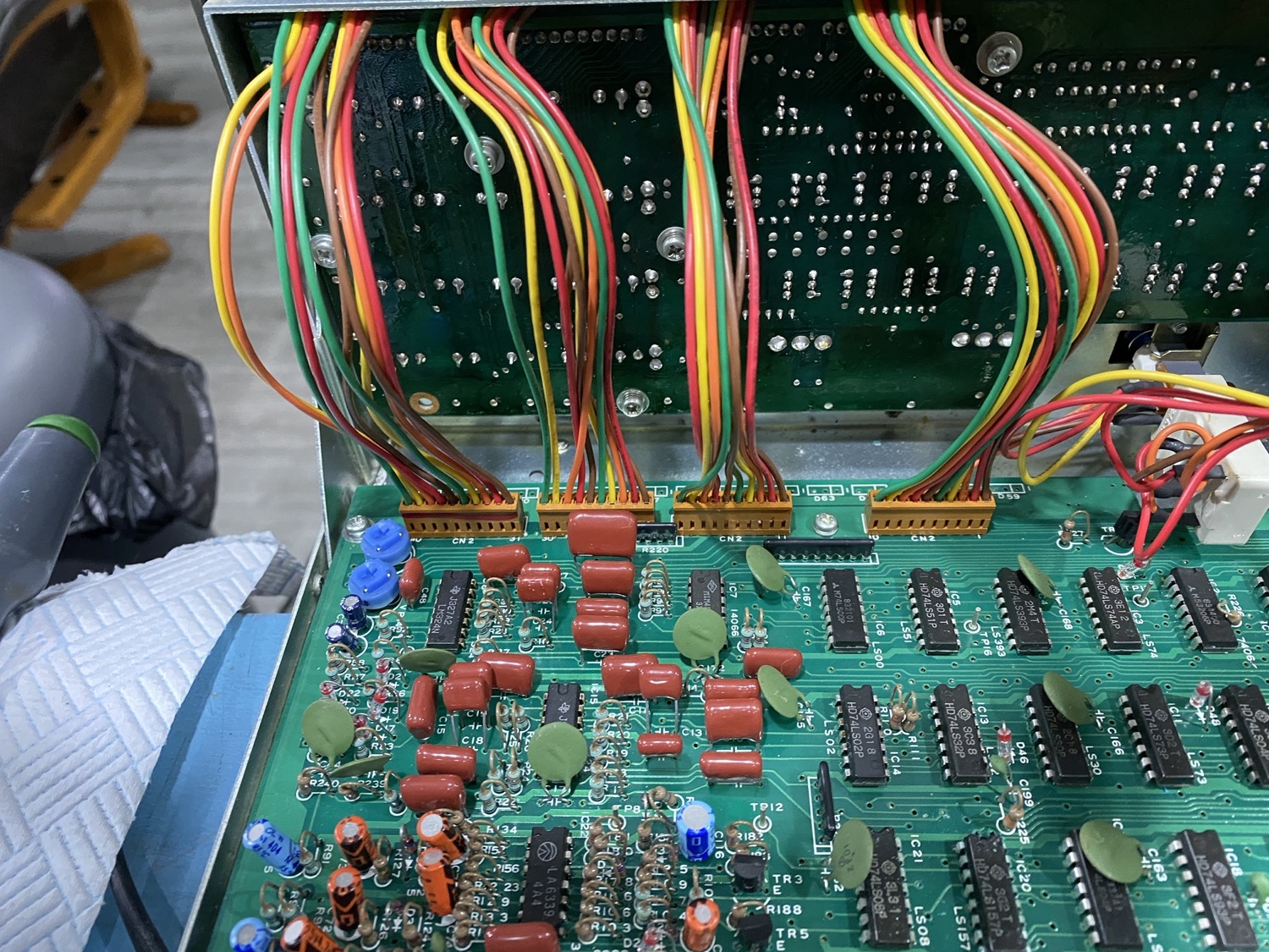
The Board is looking very clean.
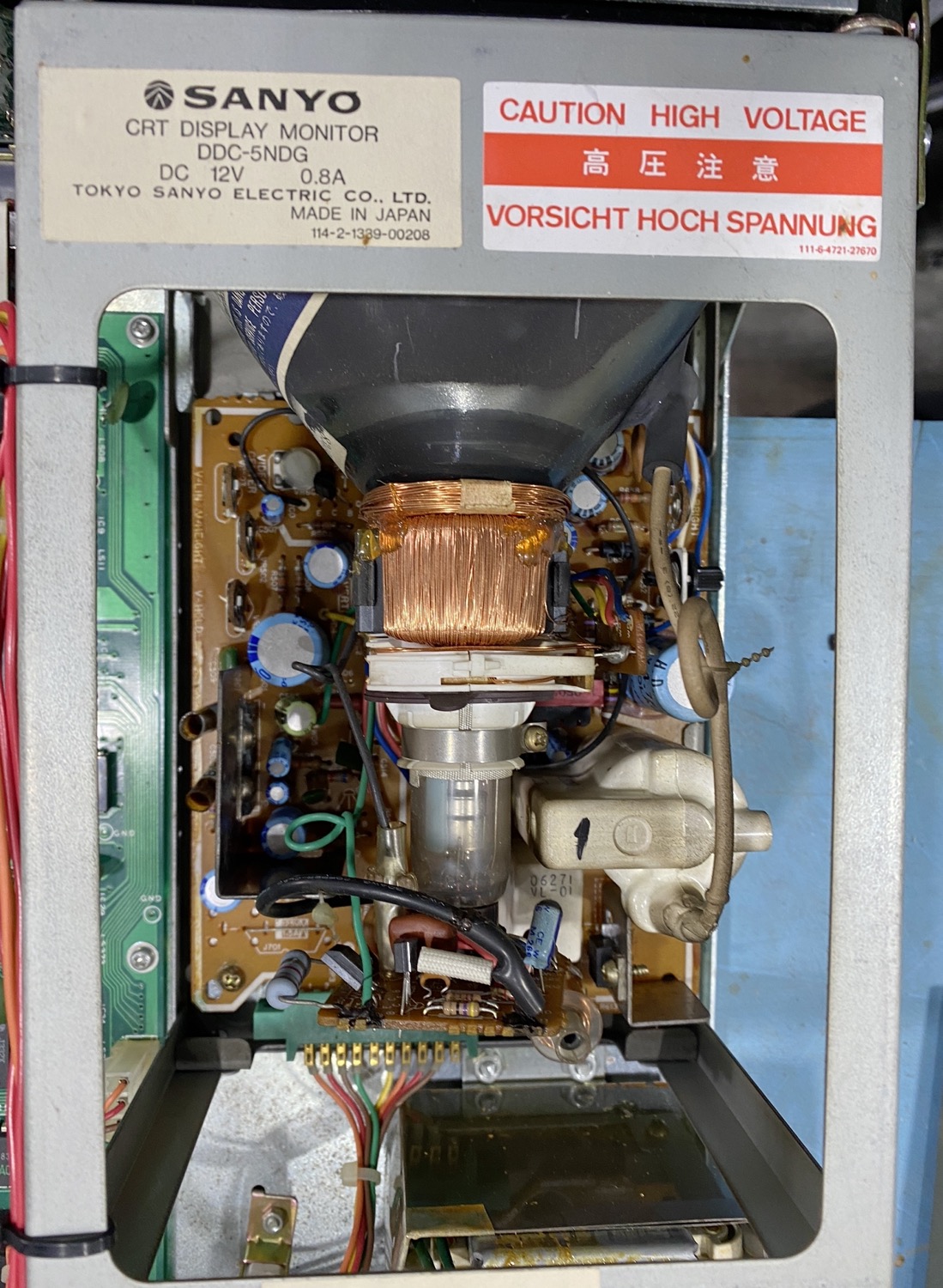
The Tube Section - Looking Very Clean
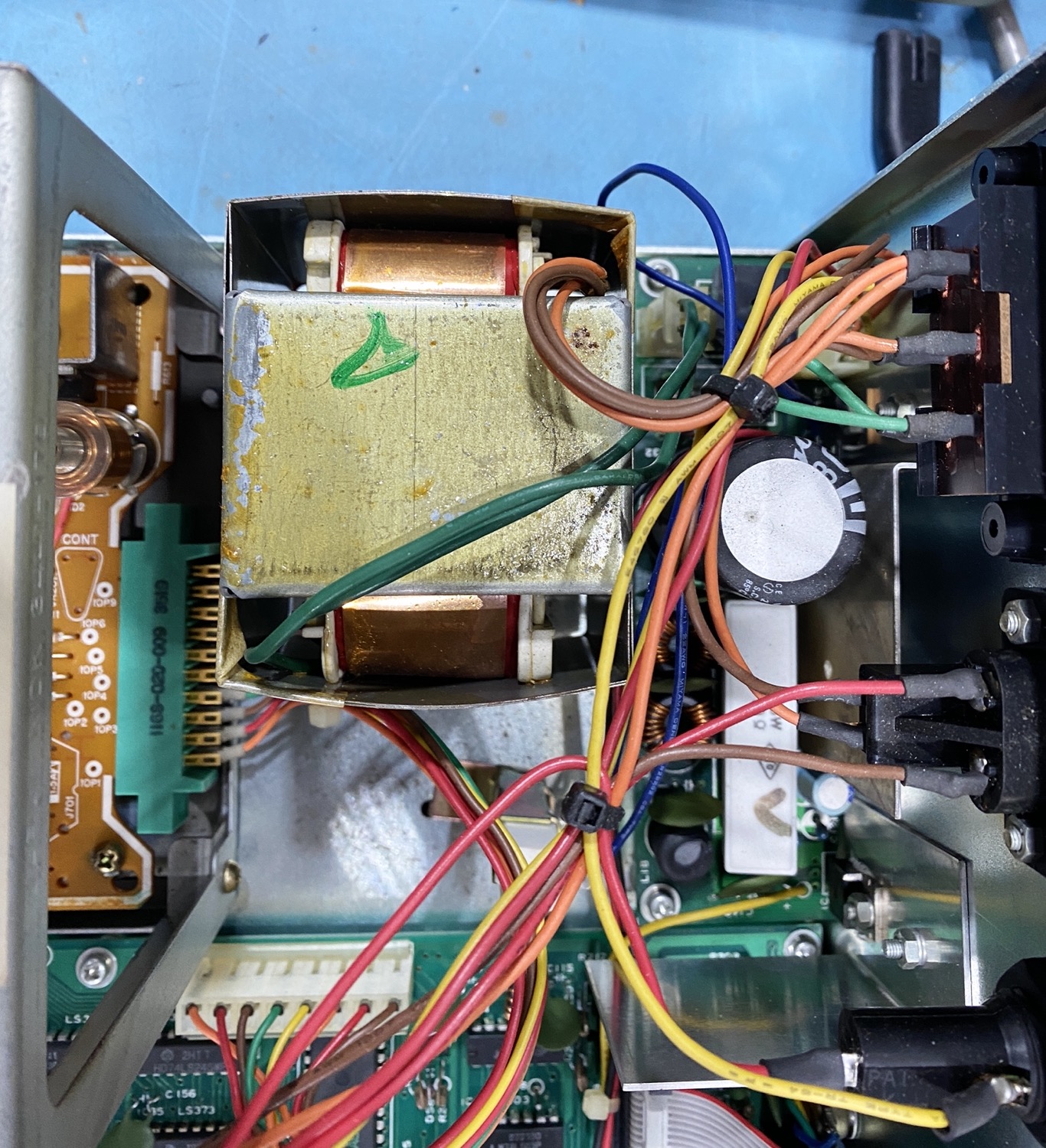
The Powers Supply Section.
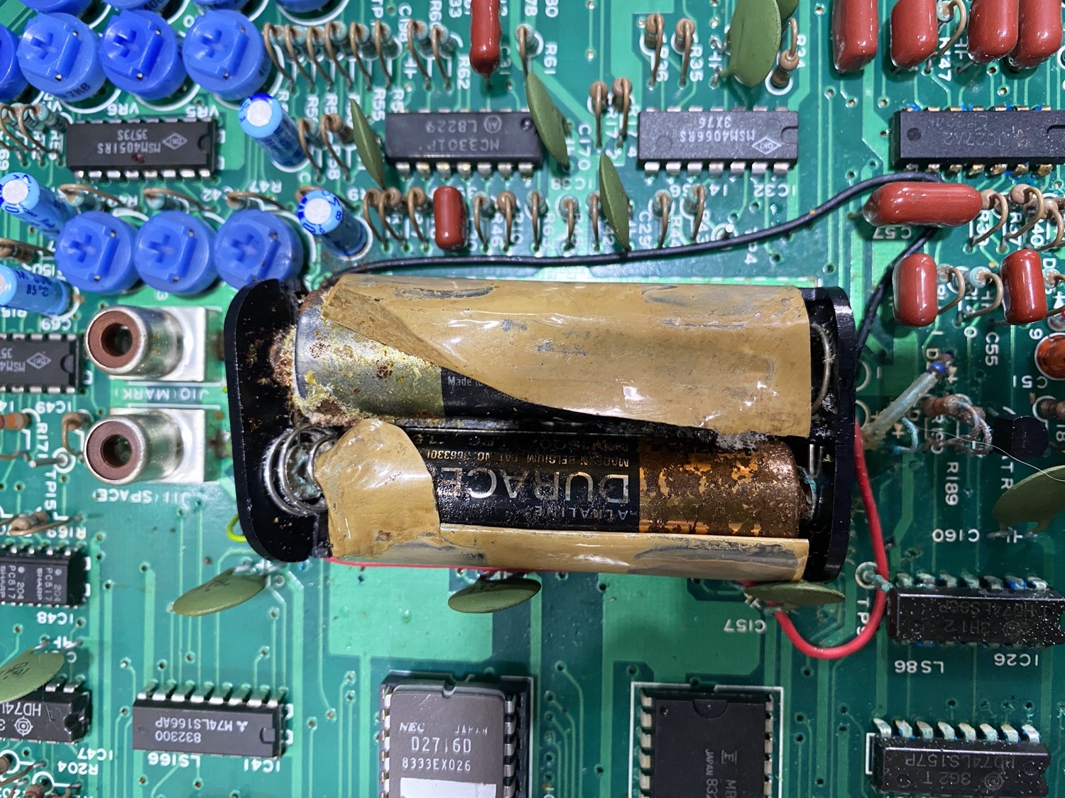
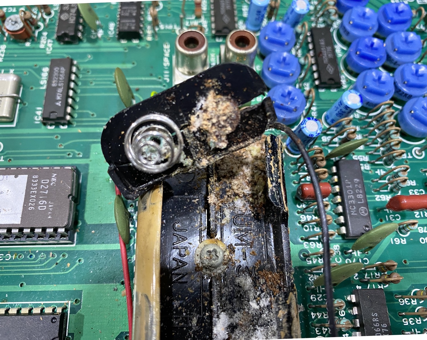
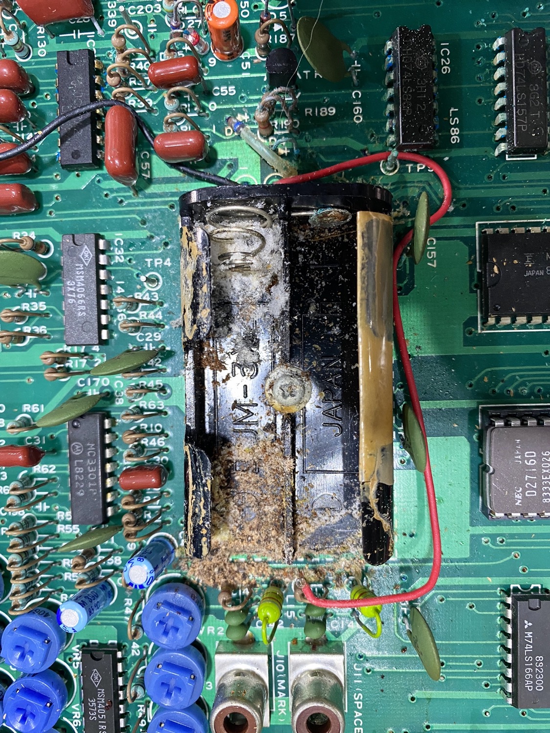
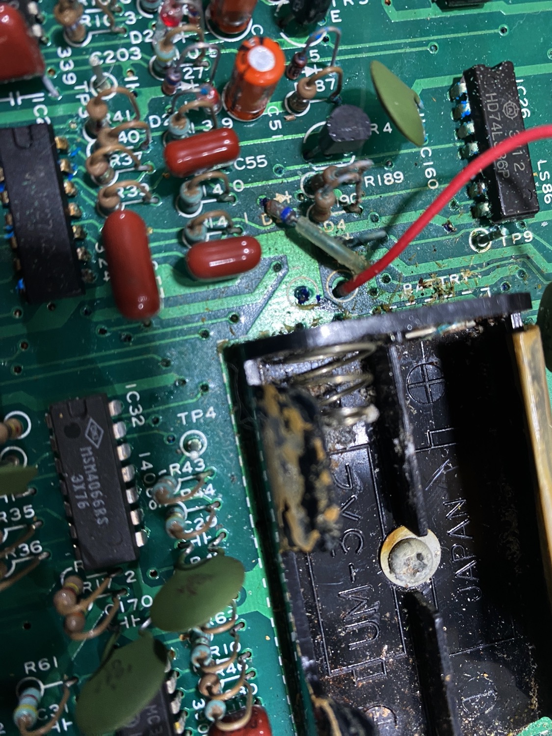
Meet the 'Elephant in he Room'
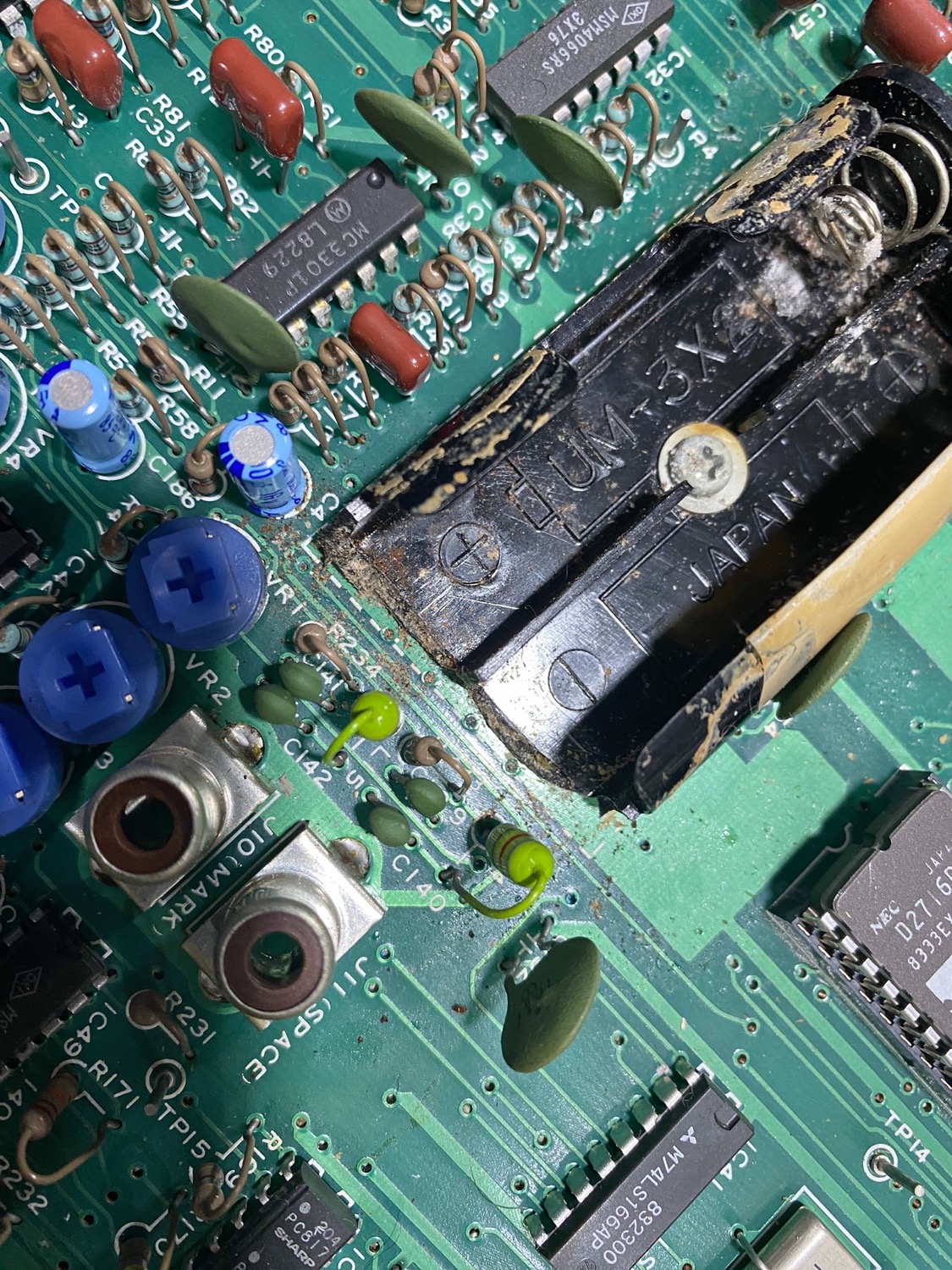
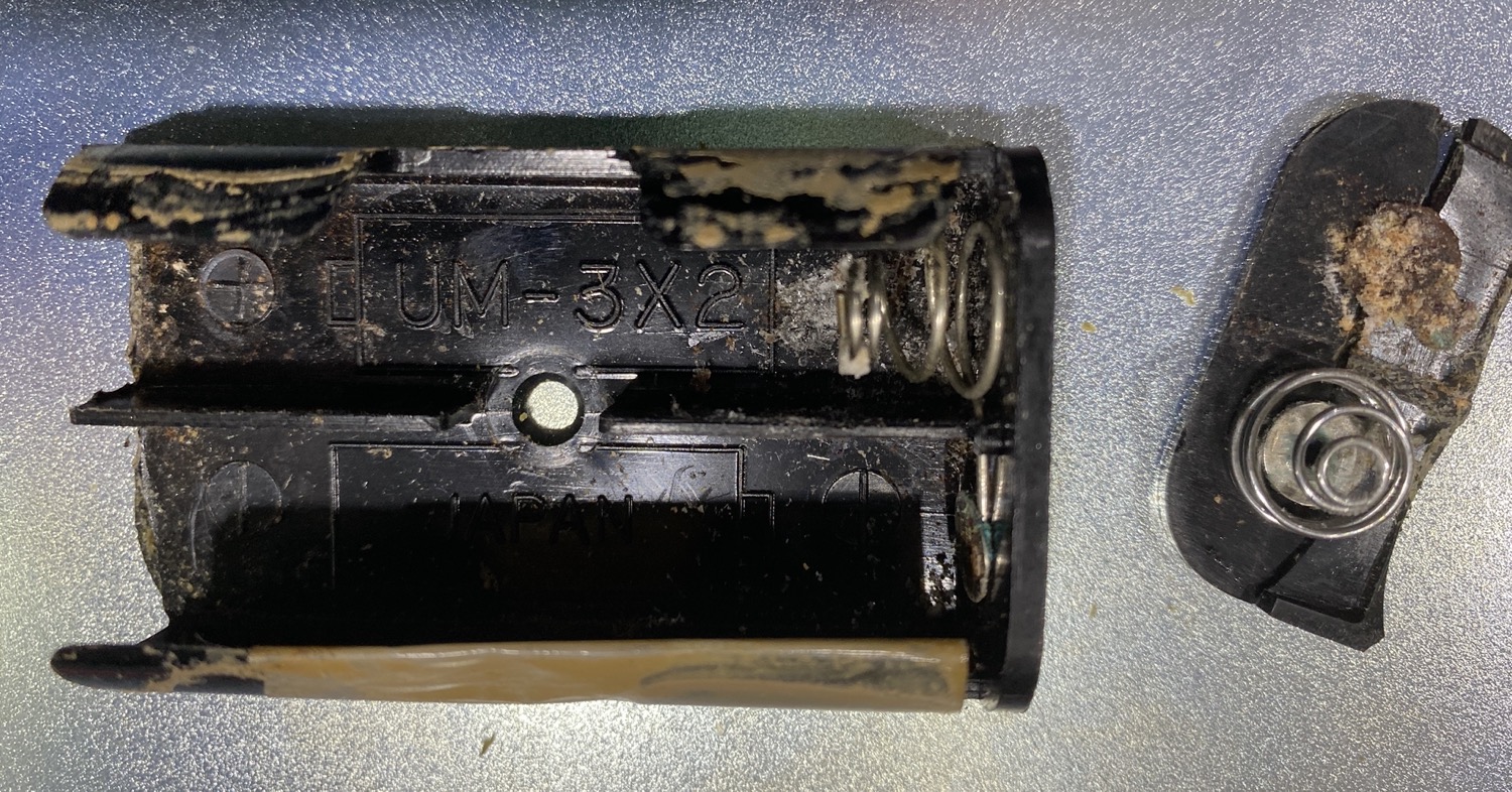
Yeah this is not looking good, and from looking at the Battery Holder, this is not going to be Pretty.
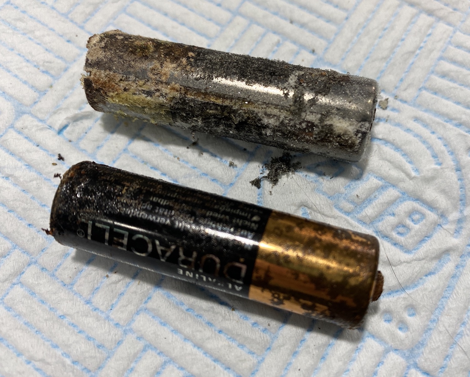
You can see that both have split and started to mess up all around them.
The Batteries Expanded as well as Split, Taking out the Battery Holder.
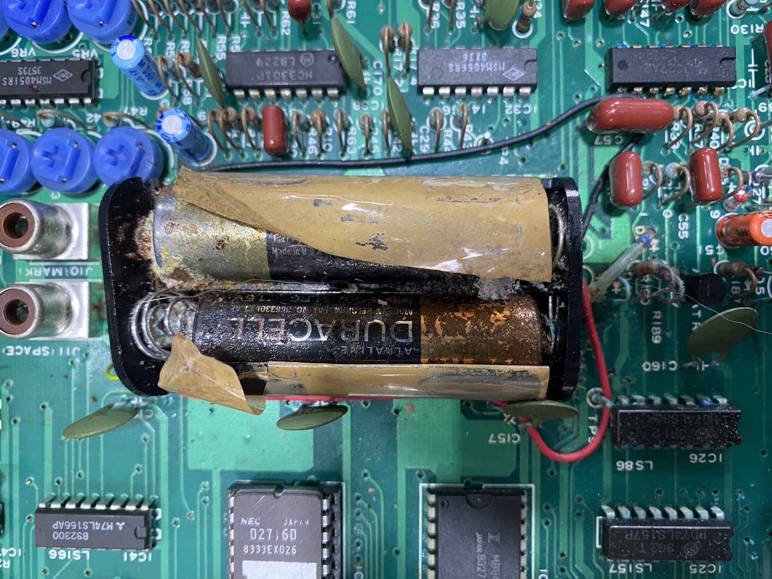
Over the years of working with mid 80’s Restorations, I have grown to hate Battery Acid, Nothing is ever as good at ruining a Restoration, but in this case it looks as though we have got there in time.
So What is left is a Mess, with some of the contents of the batteries making to the PCB with obvious consequences.
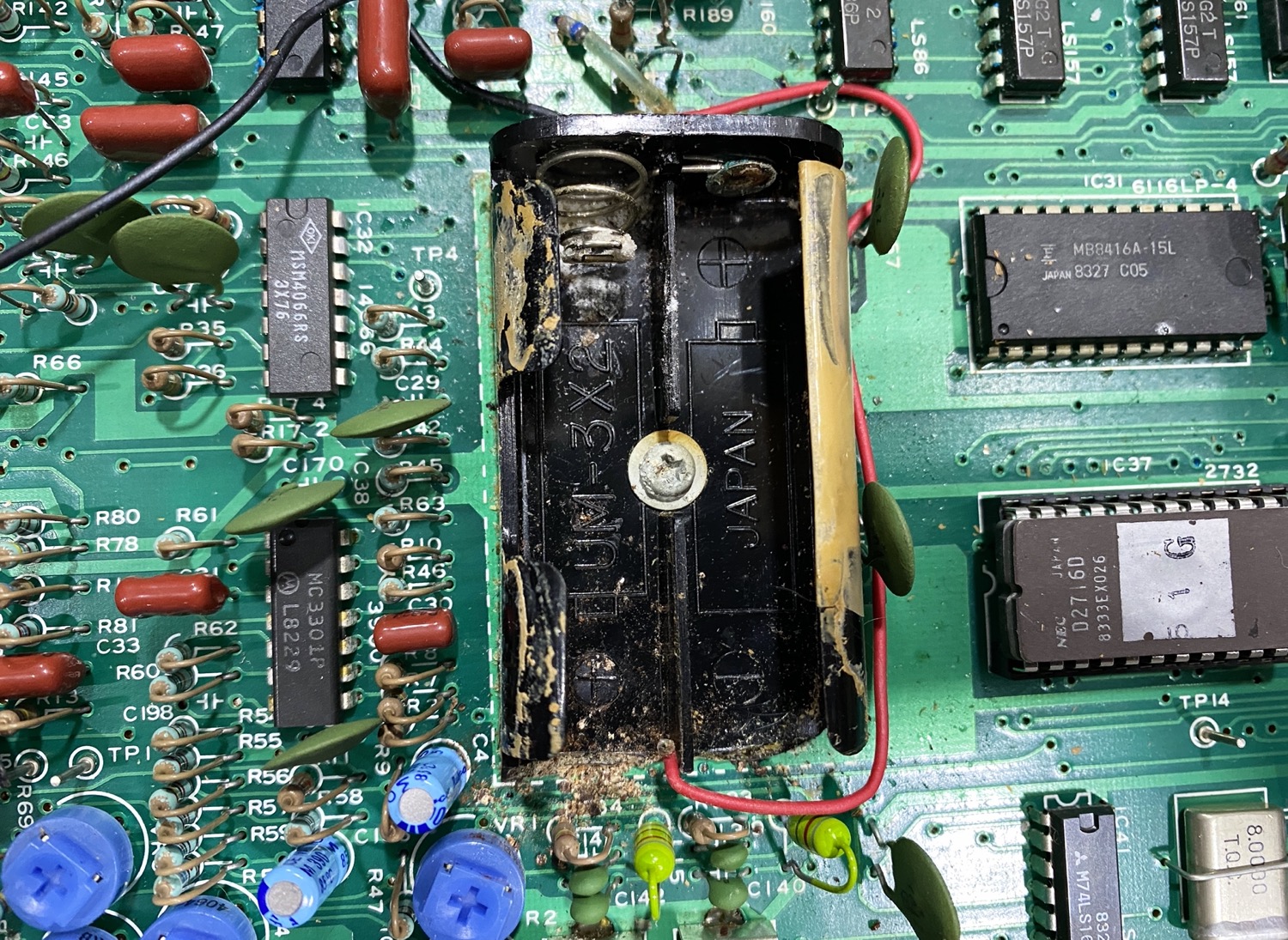
After a quick hoover and brush things are looking a little more hopeful.
At this point I was looking hopeful, but I then got scuppered at the first step, I thought that I could take a screwdriver to the Battery Holder and just undo the screw that is holding it in place, but I got thwarted here.
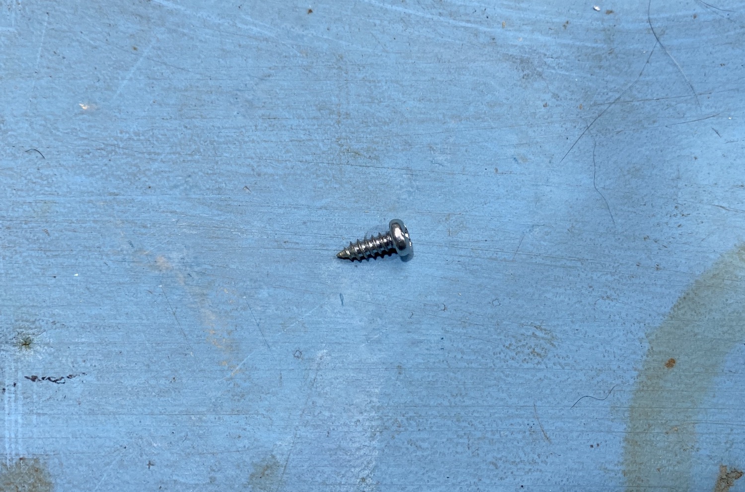
First off that is not a Phillips screw, as with all the screws in this unit it is what is very common in Japan, or at least it was back in the 1980’s, it is what is called a JIS Cross Head Screw, Using a Phillips Head Screwdriver on JIS Screws will only destroy the heads, especially if they are done up tight, you need to use a JIS Screwdriver or bit to undo them, Nowadays in the 25th Century we can usually find them for sale at a stupid cost, I found a nice little set back in the 80’s from CPC consisting of 4 screwdrivers for about £70, You can find them cheaper nowadays but be beware, if they are cheap they may not be real JIS but fake ones, there are a lot of sets coming out of China at the moment that are cheap Phillips sets, not properly hardened and will only last a week anyways, buy something proper from a good dealer.
The First Problem
It was not the ‘Rounding’ of a screw head that stopped me, I tested a Phillips, and you get the feeling that it was not exactly right, so I reached for my trusty JIS which fitted perfectly, but sadly for me this was the start of a load of other problems.
Sorry about the poor photo, blame it on Apple
If I was not already starting to make a list of things that I should not like about this restoration and finding that I have already filled up one whole page of rude words, I then find I have a few more issues with this unit.
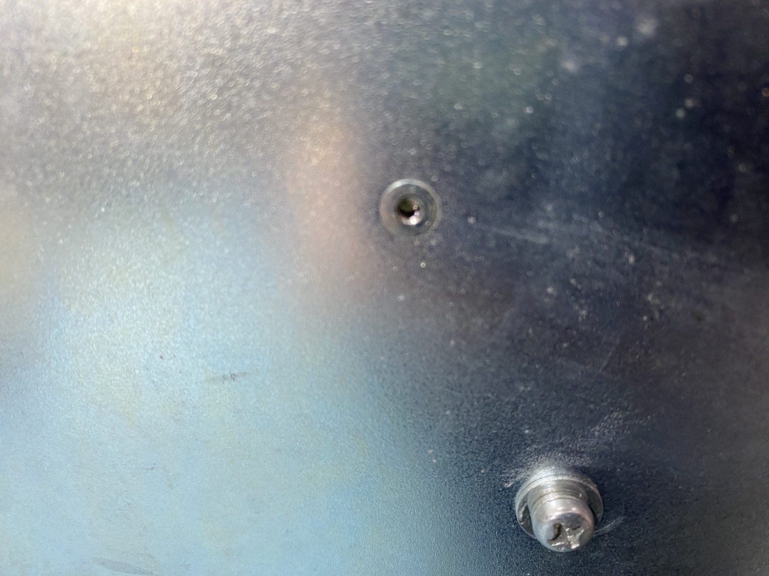
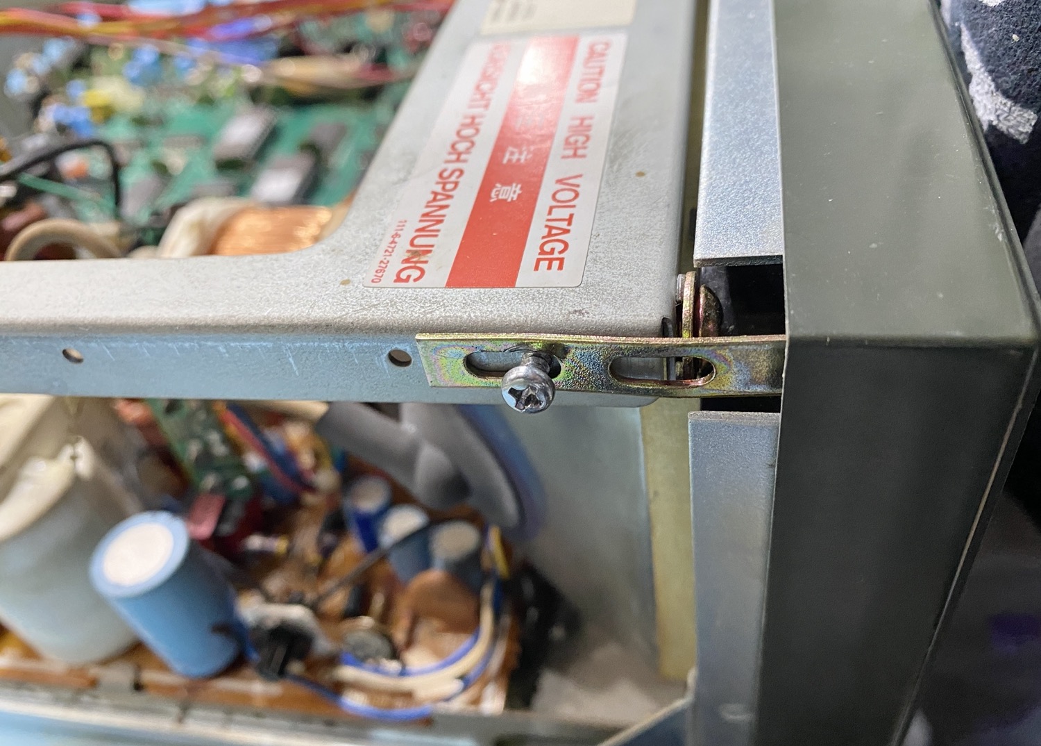
I have only once come across this before and that was with an old cheap PC case, I mean most people would normally use a tooling firm to CNC Weld in some screws for the Turrets to mount to, or maybe even just have some square holes in the based to affix with some clip in turrets of some sort, but the cheapest method I have come across before, is maybe what has been used here, It is like a rivnut, and normally they stay in place as in they do not rotate when you try to unscrew the screw from the other side, but in this case when I tried to remove the screw from the middle of the battery holder I found that the entire rivnut was also rotating so I am going to have to have a rethink here.
Bloody Cheap Riv Nut Risers, just what I wanted...NOT!
There is a hole in the back of each which shows a thread, so I may try screwing in a small screw that would hopefully just apply enough friction to hold the rivnut just long enough to hold the rear of the rivnut long enough for me to unscrew the fastening.
Well Maybe Take the PCB out!
So as I cannot seem to stop the rivnut from rotating when I try to undo the screw it looks to me like the only possible solution here is to try and take the entire PCB out somehow, to do this should be quite easy, yes there are a load of connecting wires, but it is not really too difficult, so I am going to attempt this.
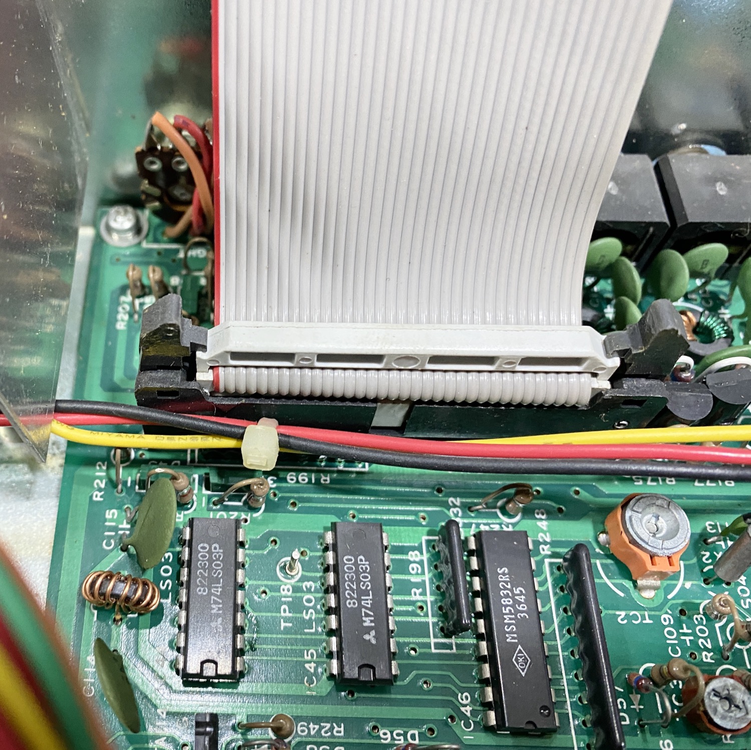
First job is to disconnect the ribbon from the board for the Printer connection.
This one is a prod from the past, the good old IDC connection more commonly used for Old IDE Hard Drives in computers of old.
Next one of those horrible connections to the Display, these are always horrible after a lot of years, they seem to just harden
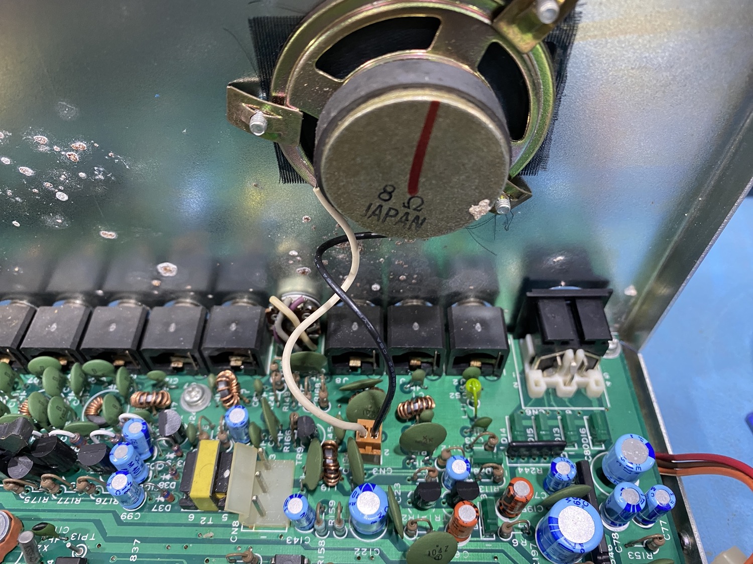
Just a standard 2 pin connection for the internal speaker.
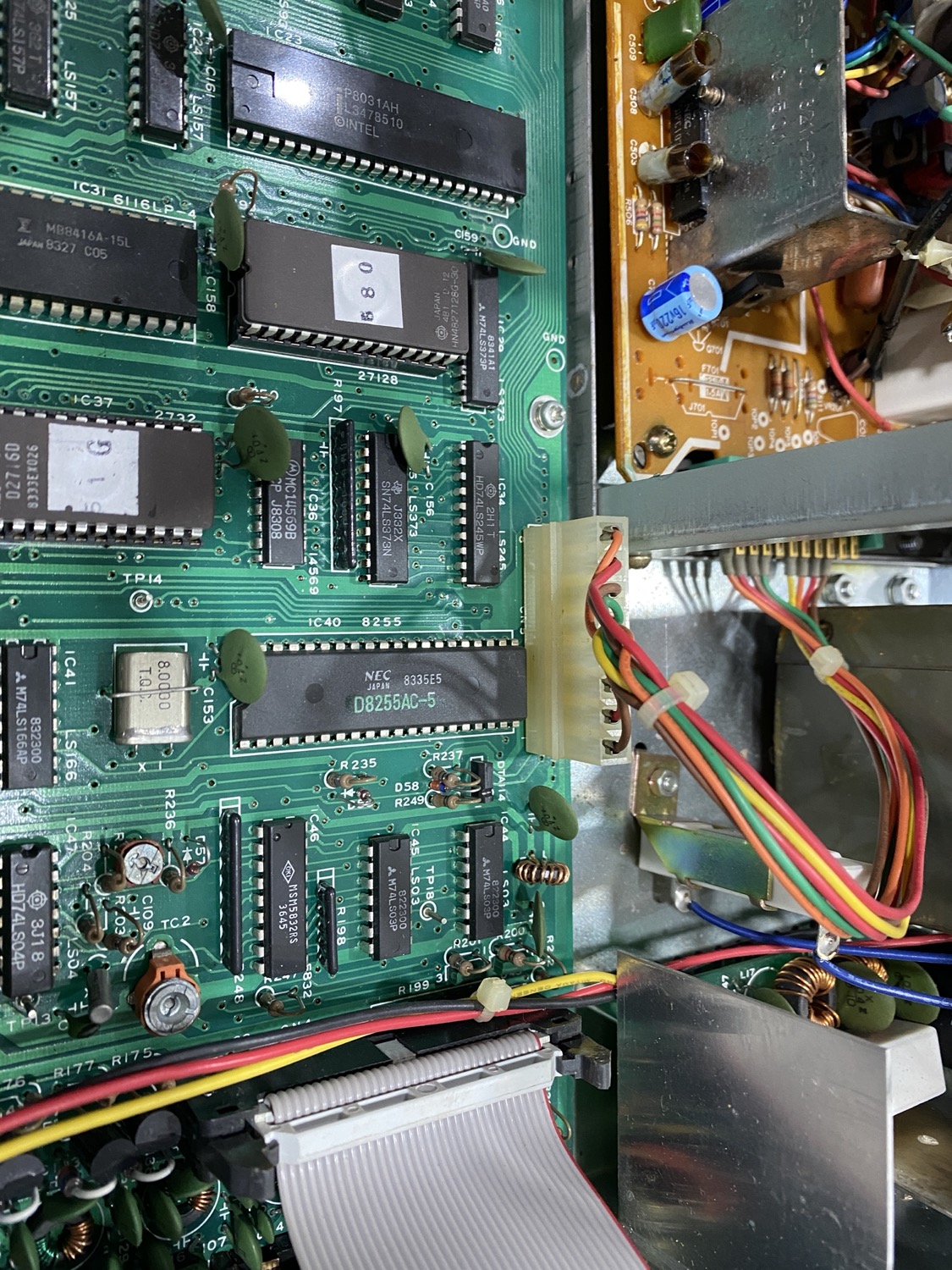
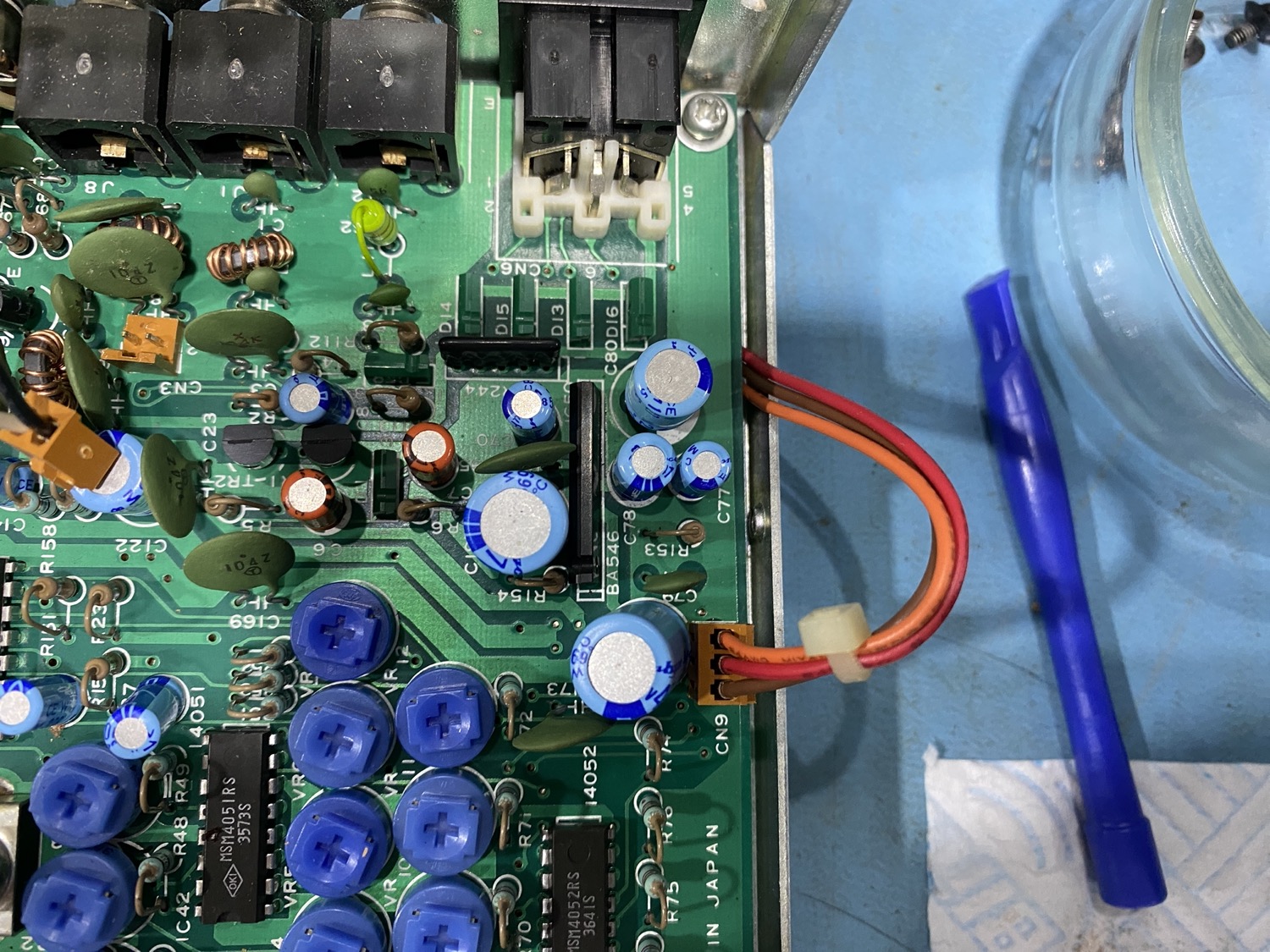
There are a few other small and 3-pin connections.
The Links to the front panel have the most connection, so with loads of photos taken, these can be disconnected.
The main power to the board can be just pulled and locked into place for the minute/
On the rear of the unit there are 3 10mm locking nuts that need to be removed before we get the PCB out, to do this was just a simple use of a 10mm Nut Driver, and like all of the other screws, placed in a small pot safe, and as I have a load of cats trying to send me around the twist, and they just love a small pot of screws, that can be knocked off this safe area and then chased around the floor for hours of fun at my saneness.
Opps, Stuck
OK a little Stuck and Taking a break to try and work out what I can do!
The Problem is one of those ‘Simple’ Tasks that should be blatantly obvious to anyone that is looking at this board.
I have taken all of the screws out, that was a bloody challenge, I know that I am week from the Cancer but nothing should have been tightened up that much, they must have used some sort out power driver to hammer home the screws, it took me a whole day just to sort this stage out, I was a little worried as some of the screws on this unit feel a bit soft and I was worried about rounding the heads, but thankfully they are now all free and safely in the pot of bits that is slowly growing.
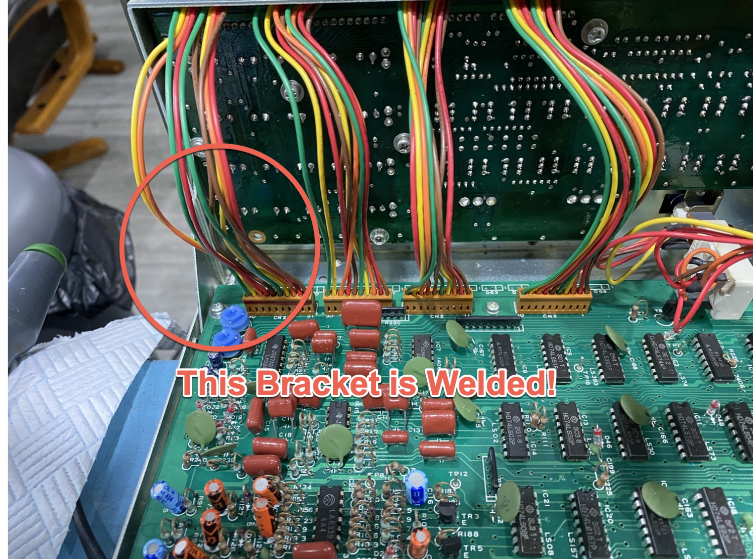
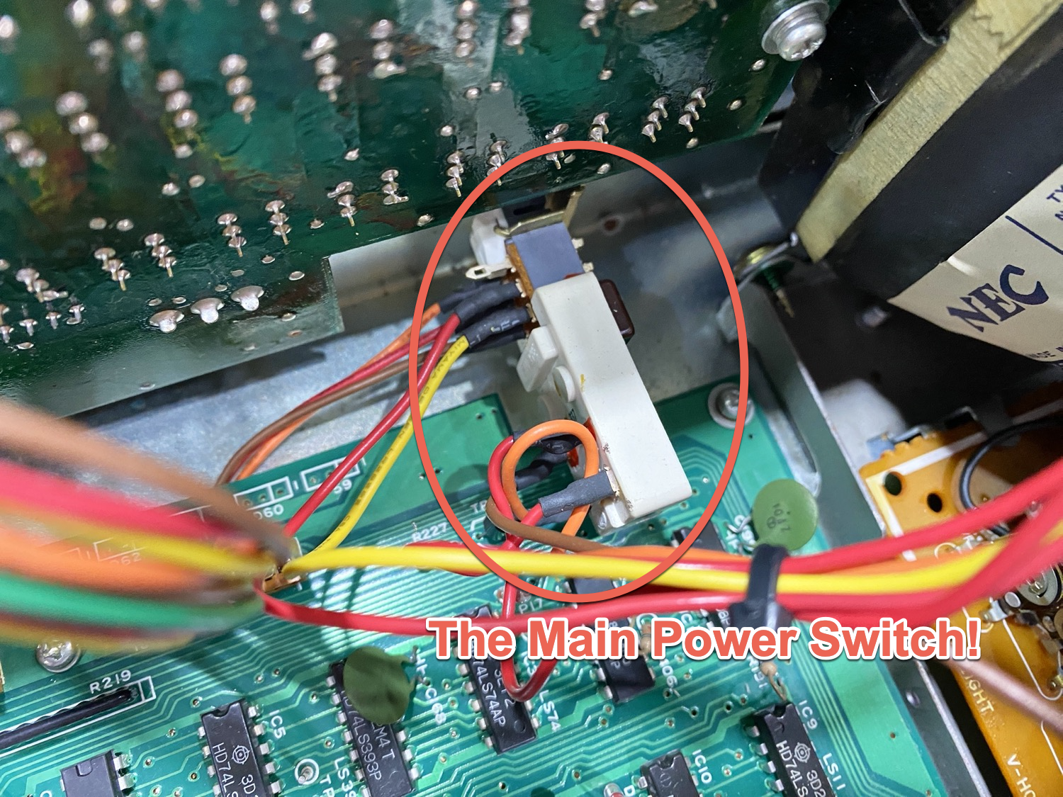
But this is as far as I have got, all of the connecting wires have been disconnected, and I can lift the board, but that is about all that I can do with this, the board is being pinned down in one corner by the Power Switch on the front of the unit, I can tilt the board in a way that should allow me to squeeze it through but for some stupid reason there is a metal plate in the corner of the chassis that is not allowing me to squeeze the board past, so I am now stuck between, actually no between, I am just stuck, the only way that I think I can get the board out is to somehow take the front panel off, but I cannot see any screws that would allow me to remove the front panel, it looks as though PCB on the front panel is hiding the screws to remove this part.
The Bracket that is welded in place!
The Offending Power Switch.
I think I must do a bit more thinking, So much for an easy quick fix.
This was meant to be Easy!
So, a simple job of removing the battery Holder, Cleaning it and then Putting the lid back on has now turned into a right mess, and what was meant to be simple is turning into a bit of a bitch.
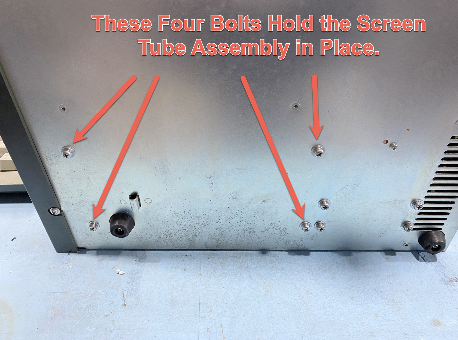
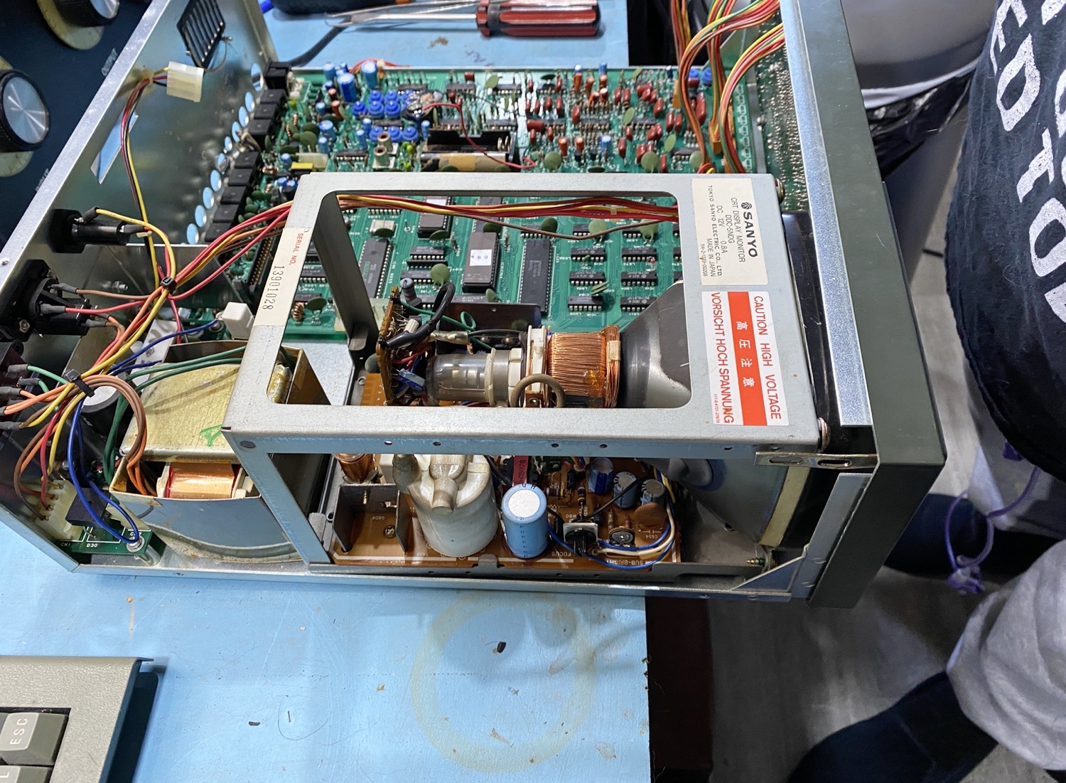
I cannot slide the board out because the Screen Tube Assembly is stopping it, well that and the Power switch, i.e. one way is blocked by the Screen Tube Assembly, the other way is blocked by the Power Switch, and working out what is the easy way to go looks like removing the Screen Tube Assembly is going to be the easiest way to go here.
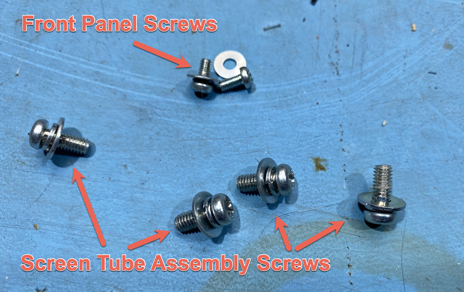
TONA THETA 5000E Sender Decoder - Front Panel Mounting Bolts
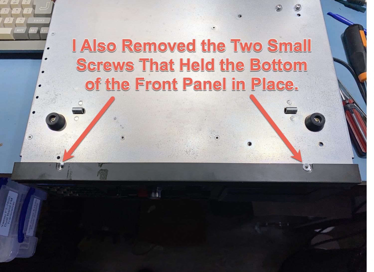
While I was removing the Screen Tube Assembly Mounting Bolts, I could not help myself in removing the 2 small screws that seem to Hold the Front Panel in place, my thinking here was if this went wrong somehow then it may save me a few seconds here are there.
As with All Restorations ‘Take Photo’s’ as you go to aid remembering when you come to rebuilding any Restoration Project, it will Help you and if the unit it ever passed on to a new owner they may want them as well, and you never know, I have started off a Restoration Project just like this and thought that it was only going to take a day or two only to find that 10 years later the build has waited for some very hard to locate parts to arrive so that you can finish the job, having a record of photo’s here is totally invaluable.
TONA THETA 5000E Sender Decoder - Screws
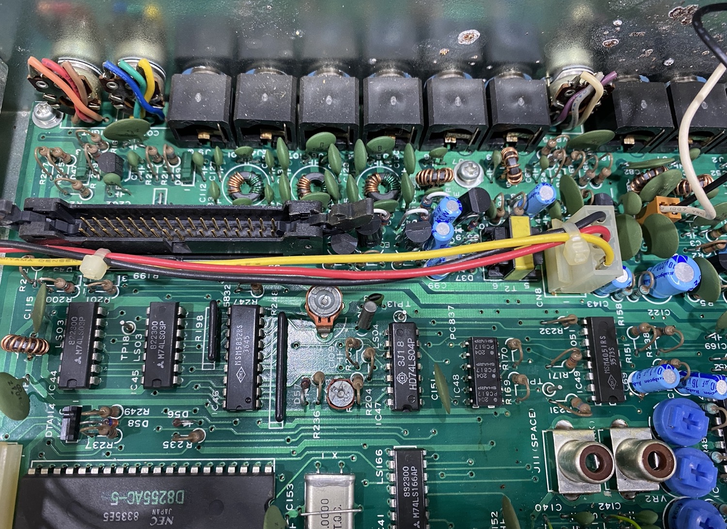
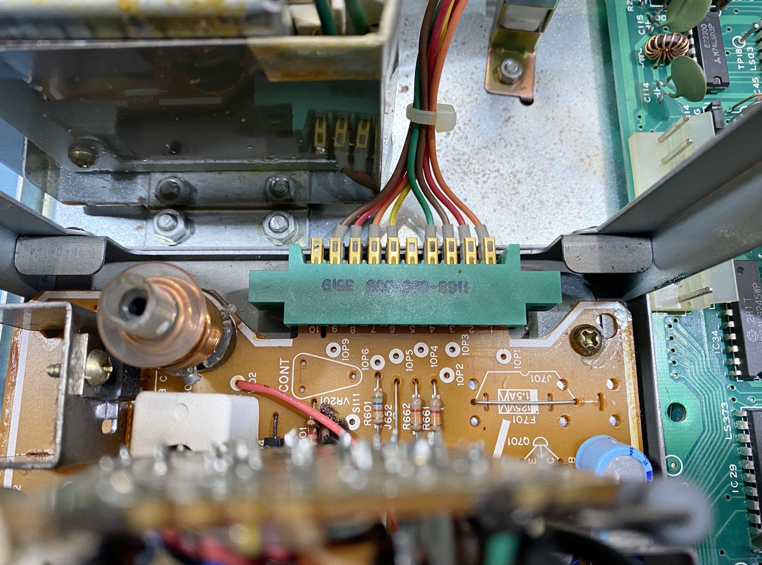
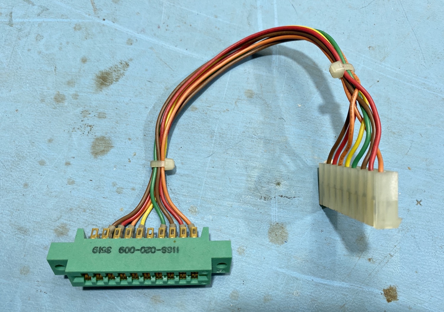
TONA THETA 5000E Sender Decoder - Edge Connector
The Edge Connector needs to be removed here. You need to be very careful here, If the unit has recently been switched on then the Tube itself will have a large voltage still held in it, its kind of like a Capacitor, that said this is a very neat way of having a tube display in a unit like this, a lot of thought went into making this Sender/Decoder, it is just a shame that they did not make the servicing a little easier, anyway back to the removal, keeping fingers well away from any components, I used the head of a large flat blade here to apply pressure to each side of the ‘Edge Connector’, just apply a small amount of pressure on each side and the connector will eventually slip off the edge of the PCB.
At this point it would be a very good idea to give this a good clean, even though they do not have to suffer like most edge connectors of this age, anything that is removed from anything during any sort of restoration work needs a dam good clean.
You Need to Remove the Self Taping Screw the fixes the Top of the Display Tube Assembly to the Front Panel.
Self Tapping Screw
Also Remove this Screw Holding the Display Tube Assembly to the Front Panel
I Am Beginning to Hate this.
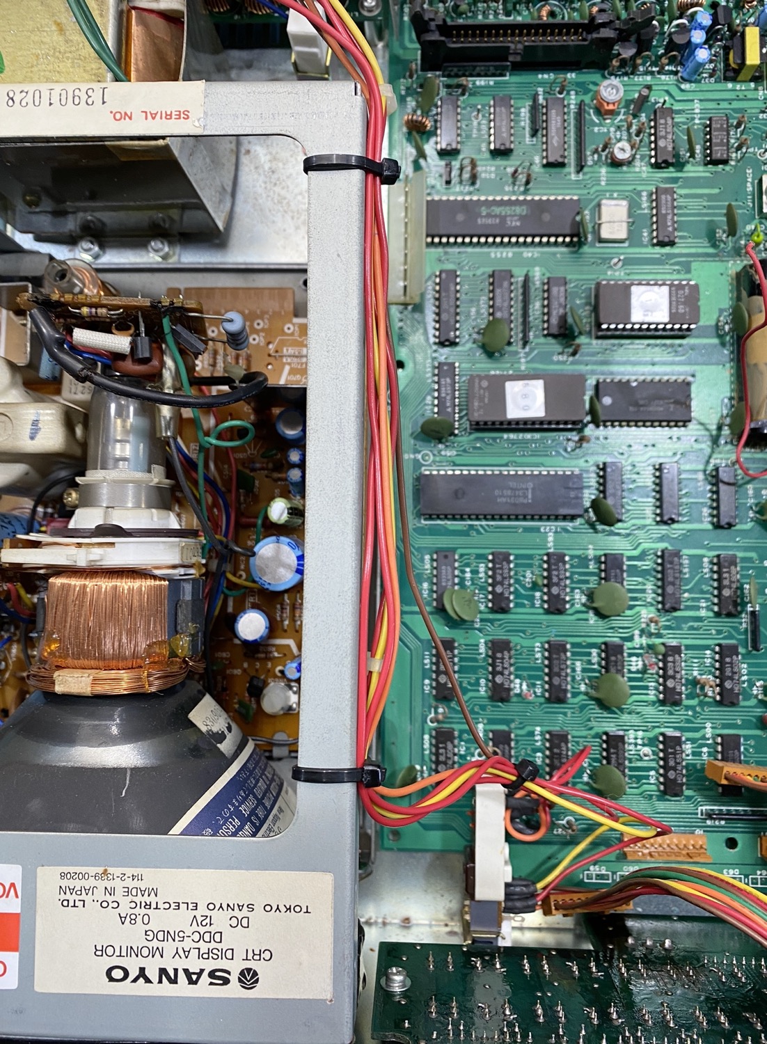
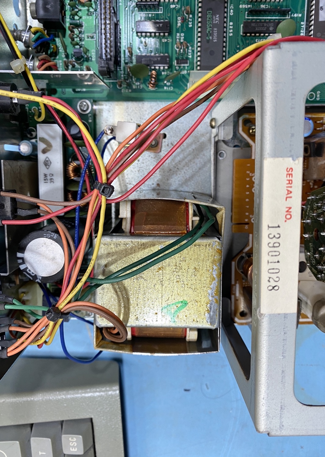
The Transformer for the Power Supply.
A 'Still' Stuck Display Tube Assembly.
THIS WAS MEANT TO BE ‘SIMPLE’, and is now turning into a bloody nightmare, Yes the Display Tube Assembly is at the least loose, but I am still unable to remove the PCB, and now I have a very delicate Display Tube to worry about.
Now for a bit of a rethink.
I am NOT in the Mood for this!
TONA THETA 5000E Restoration - The Board is Out!
The problem with the Cancer is that I have good days and quite bad days, the problem is that I have been hitting the bad more than the good, so a few days later than was meant, so I am sorry for not getting this sorted before now.
In the end it just took a bit of – ‘Oh Sod iT’ attitude and for me to get a little rough with it, that and I was not looking forward to undoing something else to get the board out and sure enough, with a delicate but forceful bit of tugging I was indeed lucky and the board came out.
The Offending Nut that caused me to strip this down. But like all good plans, they normally bite you in the bum, i.e., with the nut removed, the battery holder stays in place, which means, somebody stuck it down as well as the nut, Arrrr!
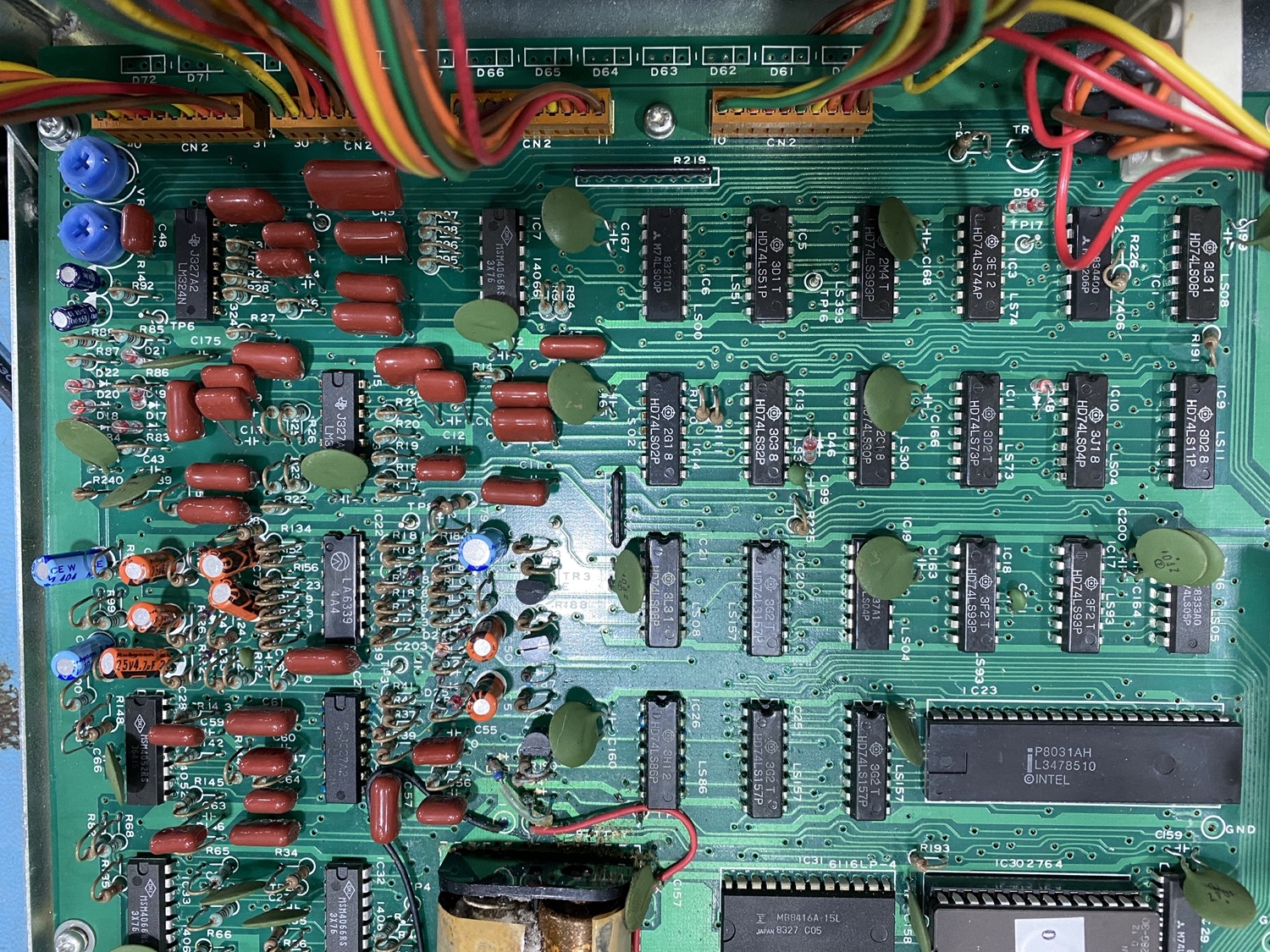
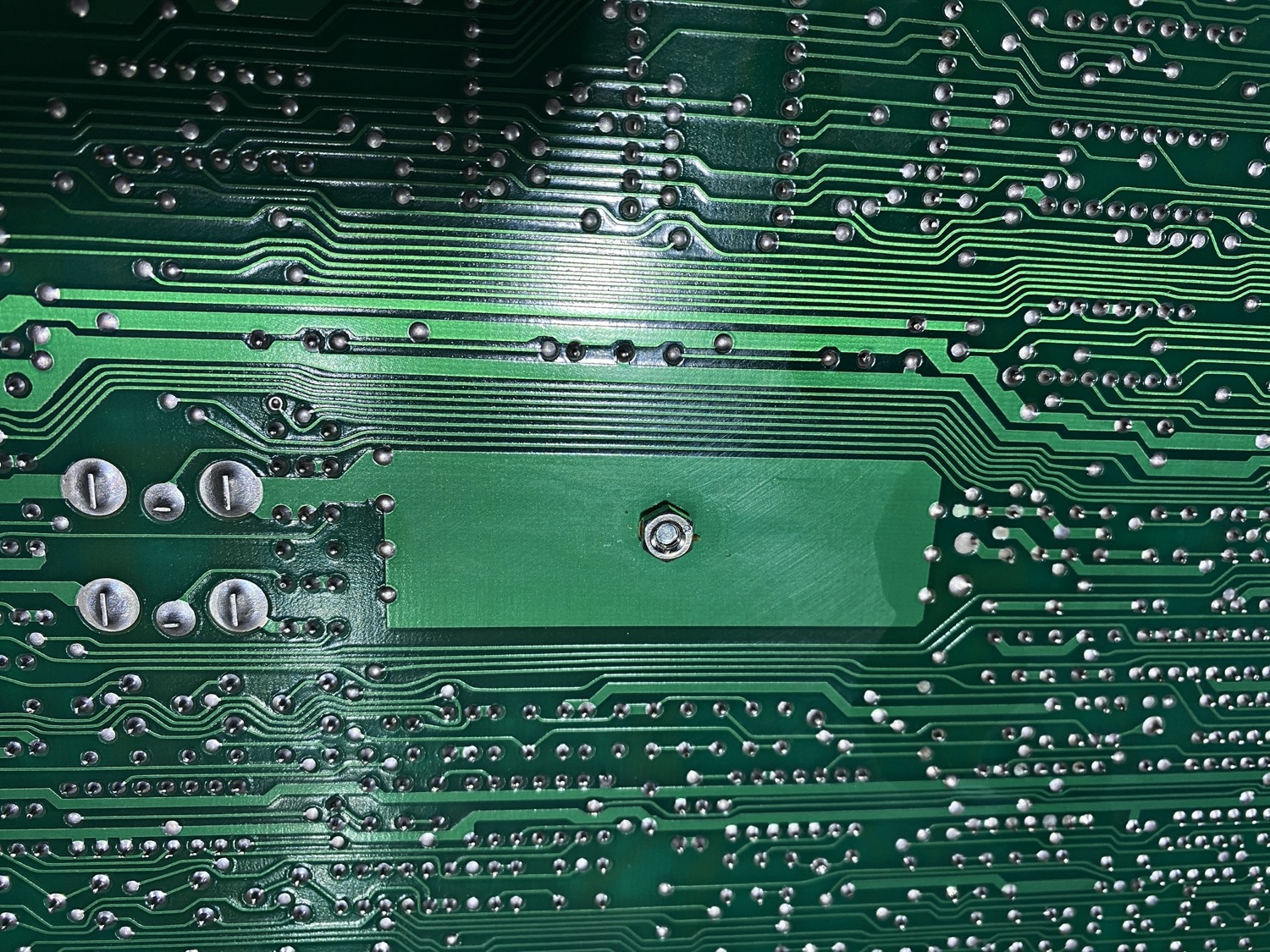
With the Board Flipped over we can see what has been causing me so much grief.
Just by chance, turning the board over, and the black wire falls off.
The Tell-tale sign of leaked batteries.
The Nut came off alright without any difficulty, but the Screw was a little more annoying, turning over the board a few times only managed to shake loose the black wire from the PCB, the screw came out eventually with a little more force from a plastic spludger. I guessed the next part – Some muppet had also stuck the battery holder to the PCB
The Battery Grip now Removed.
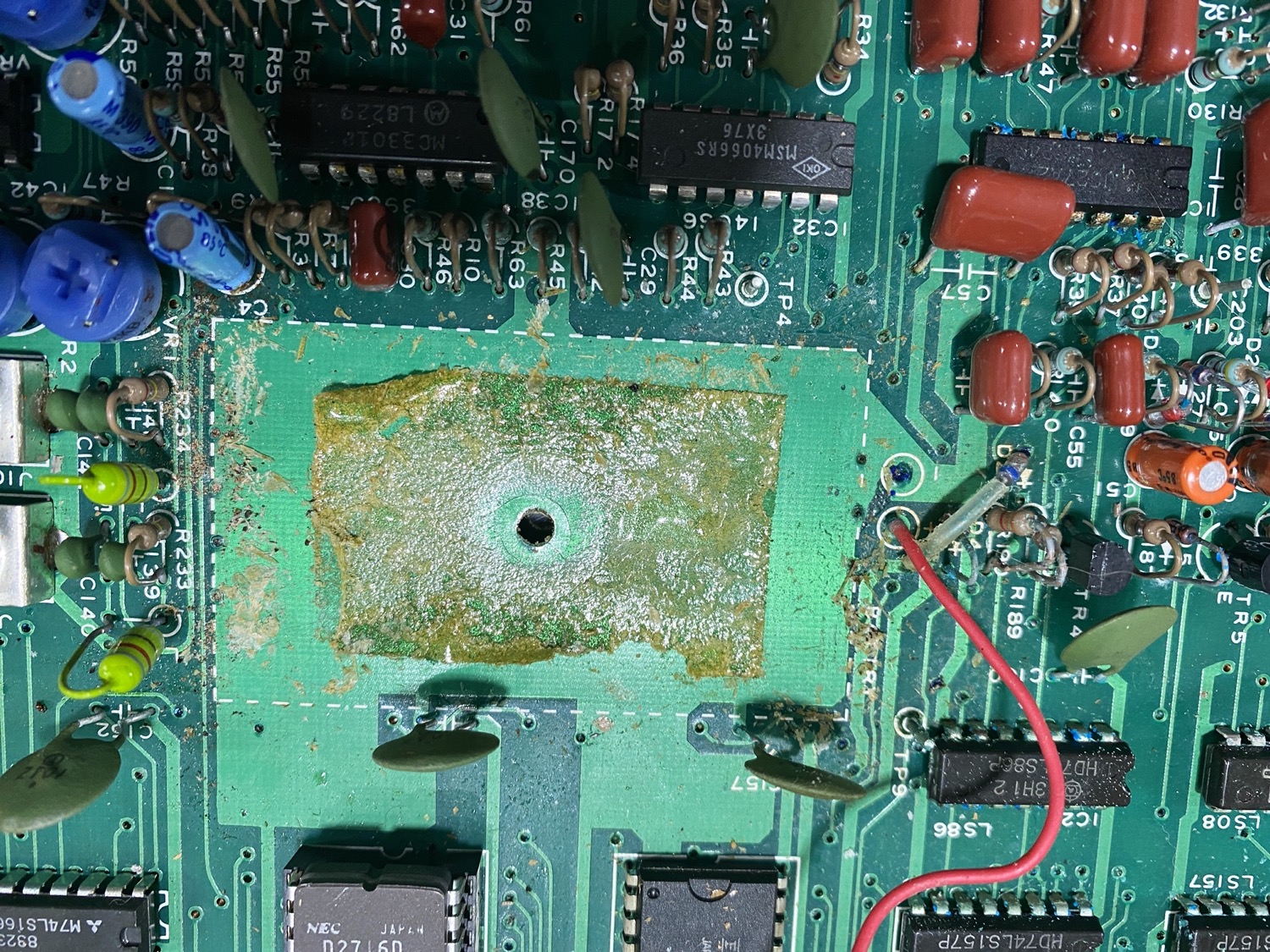
The Yuk left behind on the PCB once the Battery Holder was removed.
At this point I am calling a halt; I have to
Scrub off the glue and clean the PCB,
Find a suitable battery holder that will fit the space, and finally
Clean any residue of the battery contents off the PCB.
I will get back to this as soon as I can…
The Rebuild - About Time!
This has been a rough time for me, and I has annoyed me that this simple job has taken such a long time, I have been busy though, in between the bouts of illness which has either left me in bed, in pain, and not having the energy to get out of bed without help, or I have been found sat in front of the computer where I can be found just staring at the screen trying to get a bit of motivation, it certainly has taking a long time trying to get this working.
I cleaned up the top service of the PCB with some white vinegar first to neutralize the acid from the batteries, after this I let it dry and then cleaned up the surface with some Isopoll and finally many months later or at least it seems like it, I finally de-soldered the old power leads from the previous battery holder, This displayed a little side kick somewhat, I tried to clean up the old solder but for some reason this was a real pain, even adding new solder to the solder pads and using tones of flux did not manage to sort out this problem, in the end I drilled out the hole using a Dremel and then inserted the wires from the new connector and then applied new solder, and then once I was happy with the soldering I finally re-attached the new battery holder.
New Battery Holder for the TONA 5000E Sender Decoder
So, with the Battery holder finally screwed down to the PCB I then reattached the Screen Tube Assembly, this was more of a necessity as I would need to move the chassis upside down a few times and certainly would not want to damage this part.
Downloads
I did a quick search on the Internet and came up with this document, it’s quite handy for me as it’s like learning how to use a new piece of Hardware as I forgot the basics when I was showing this to a friend, I am still looking for a good Service Manual if anyone has one out there.
I am now retired and living on the Isle of Man, my background is as varied as it gets, ranging from Information Technology to Graphic Designer and 3D VFX Artist, using and teaching Autodesk Maya, Softimage, and Smoke, one of more enjoyable positions. Since Moving to the Isle of Man I try to keep myself to myself and work on the house, I don't do much with regards to Amateur Radio or Electronics anymore, but I am still interested in the hobby and may well get back into it one day....