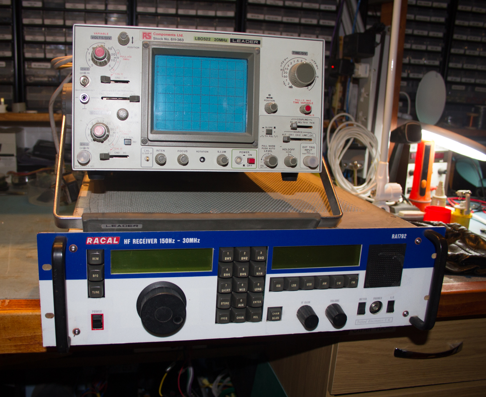
Racal RA1792 Receiver Display Repair
Morgan Griffith’s (MD0DXW) asked me if I could fix the displays on his old Racal RA1792 receiver that I gave to Morgan some time back.
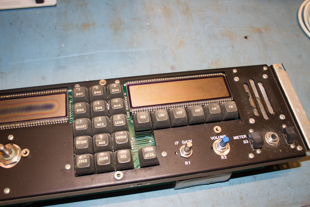
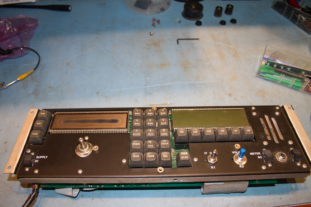
The only issue with the unit was that the displays were basically burnt out, this is a common fault with the units and one that could hopefully be fixed fairly easily.
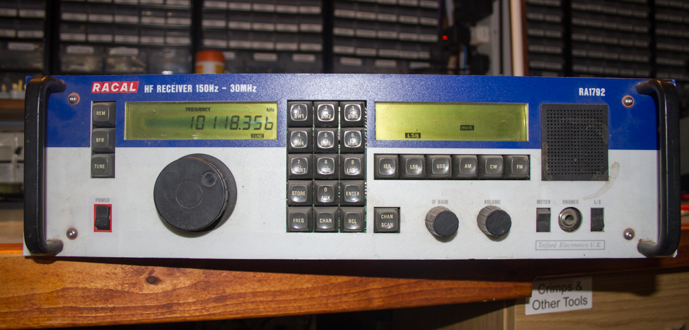
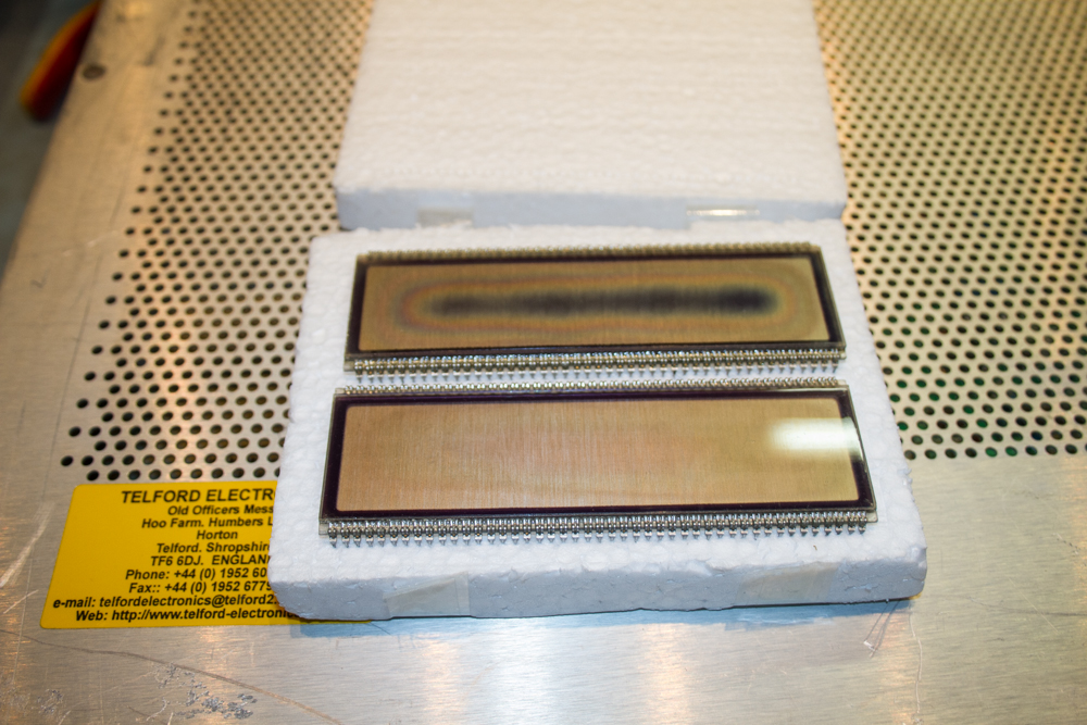
As you can see the displays do degrade really badly in these old units, and can often turn an very good receiver into something totally useless.
Thankfully there is a company in Italy that make very affordable replacement parts for these units, So after paying for them via Paypal, we received the units within a week and all I need then was Morgan to pop round so that he could watch the installation.
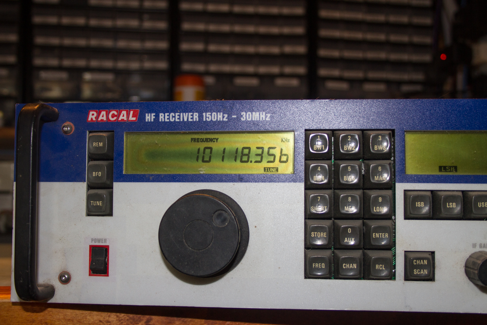
First job was to remove the top cover so that we can get to the front cover plate.
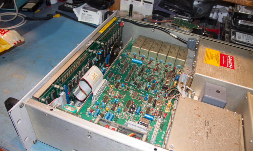
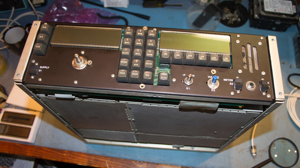
Once the top cover was removed we needed to take off the front display plate, this is held in place by two small allen screws on each side of the face plate just by the handles.
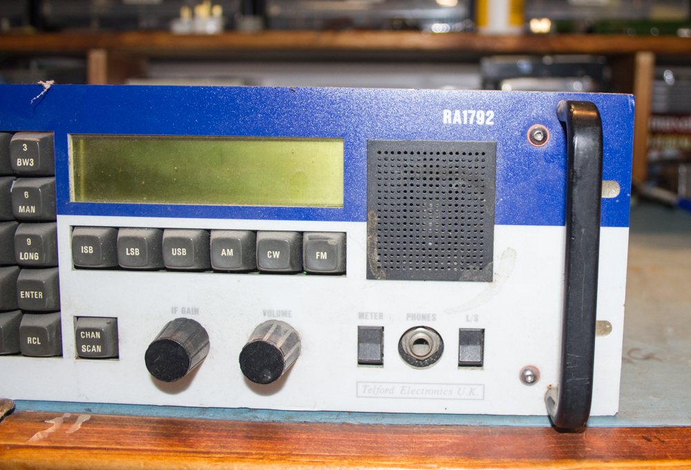
Next we need to remove the ribbon cables that attach the front unit to the main body of the receiver, this is fairly straight forward, and there is no need to make a note of which goes were as due to the different sizes and locations of the cables there is no way that they can be mixed up.
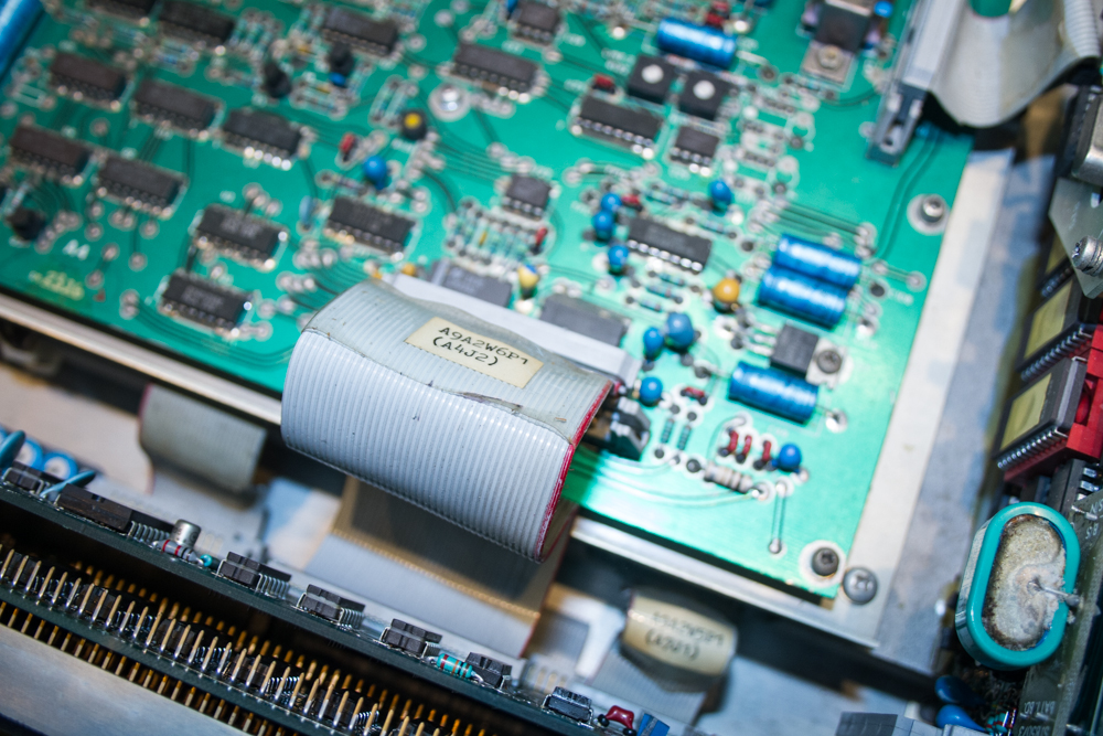
All of the cables are IDC connections and just pull apart really easy.
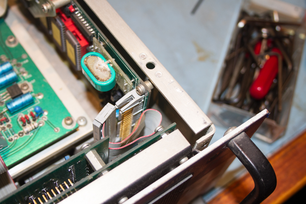
Before the face plate can be removed, the bottom cover needs to be removed.
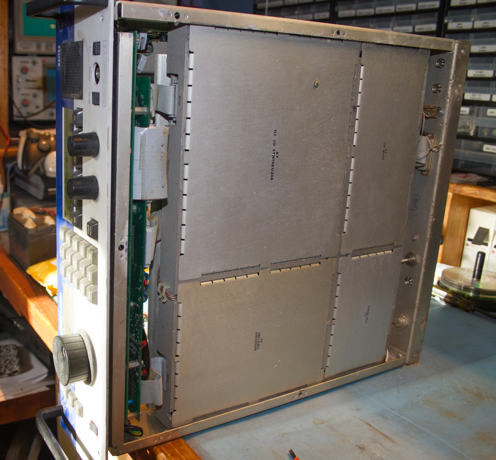
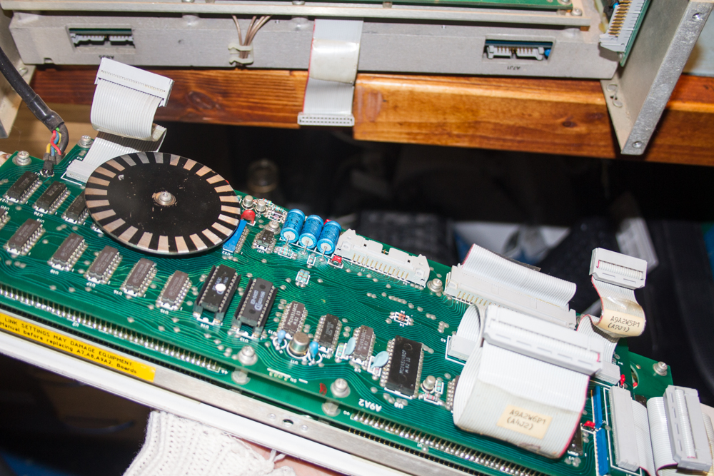
With the bottom cover removed you can now fold the front plate flat to gain access to all the cables that were a little difficult to see before.
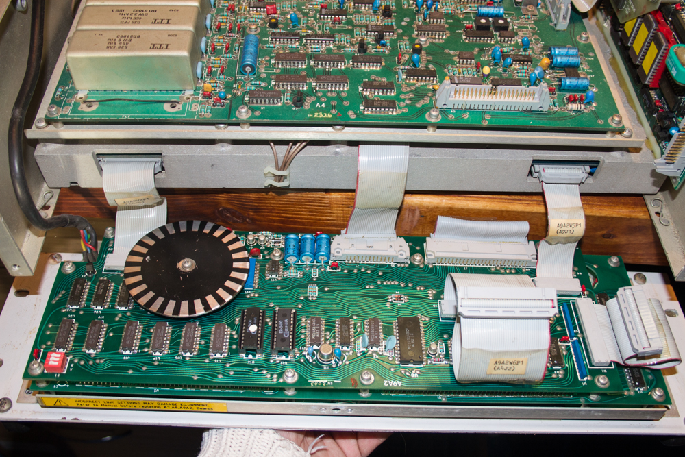
The last cable to remove is the power cable to the head unit, this is a 9 pin D-Type connection (the type used for PC serial connections) and is held in place by two spring clips, one above and one slightly more awkward to get to underneath the plug, once these are un-clipped the plug pulls straight out.
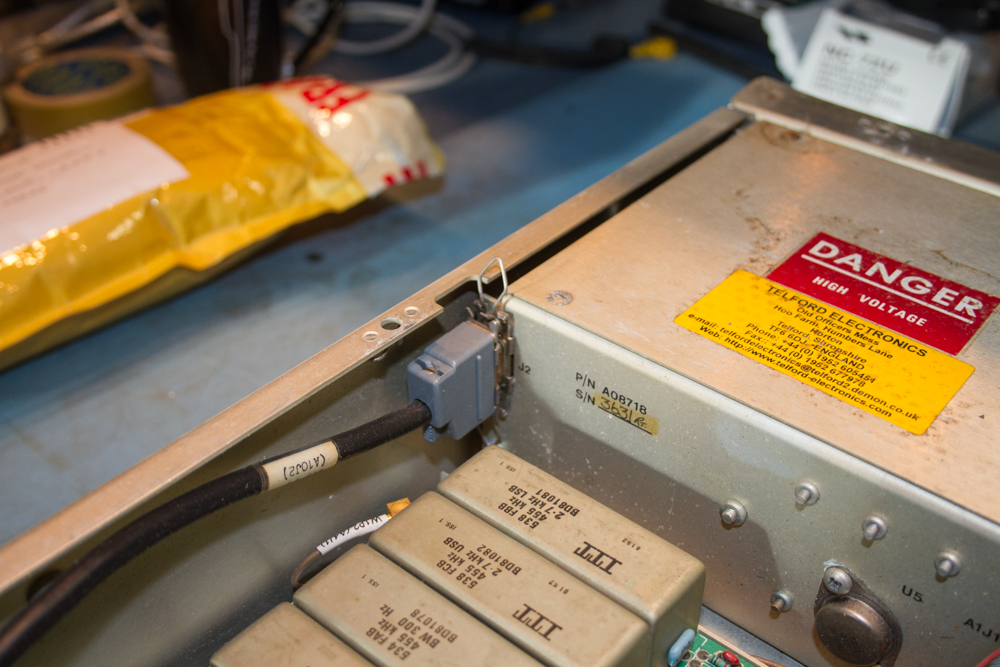
The head unit is now free to be removed from the main chassis.
To remove the main plate off the front unit we need to remove the three knobs that are in the way, these are thankfully very easy to do, just remove the top caps off each knob and then using a 8mm nut spanner you should be able to loosen off the nuts that hold the knobs in place, the knobs will just pull off with a little persuasion.
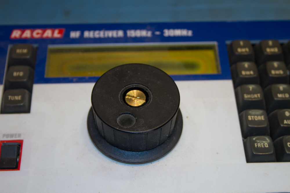
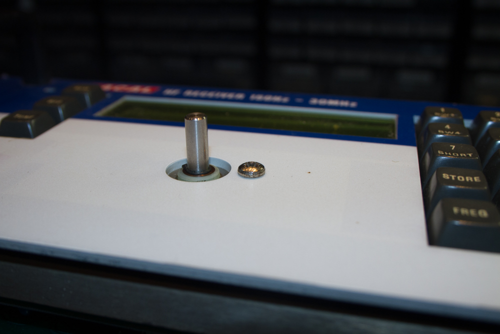
The main VFO knob is basically the same, using a sharp pointed scalpel blade to remove the middle insert to reveal the slotted nut underneath, and again with a little persuasion the knob will then just pull off.
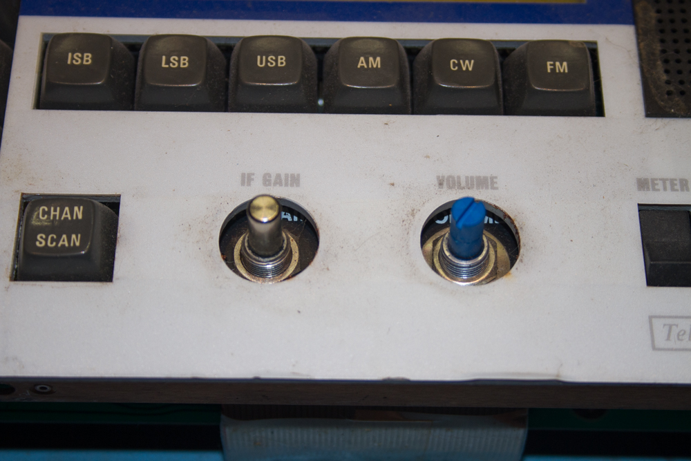
The last job is to remove the screw that was hidden underneath the VFO knob.
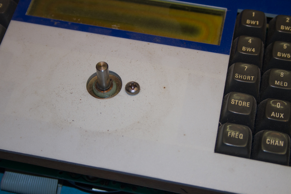
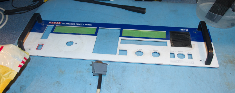
And that is it, the main plate will simply lift off and can be placed to one side to be cleaned by a helpful Morgan if you have one! (if you don’t have one, I can hire mine out for a small fee, hi hi).
Now we get to see the two display units, the worst one of the two is the frequency unit that is on the left of the face unit.
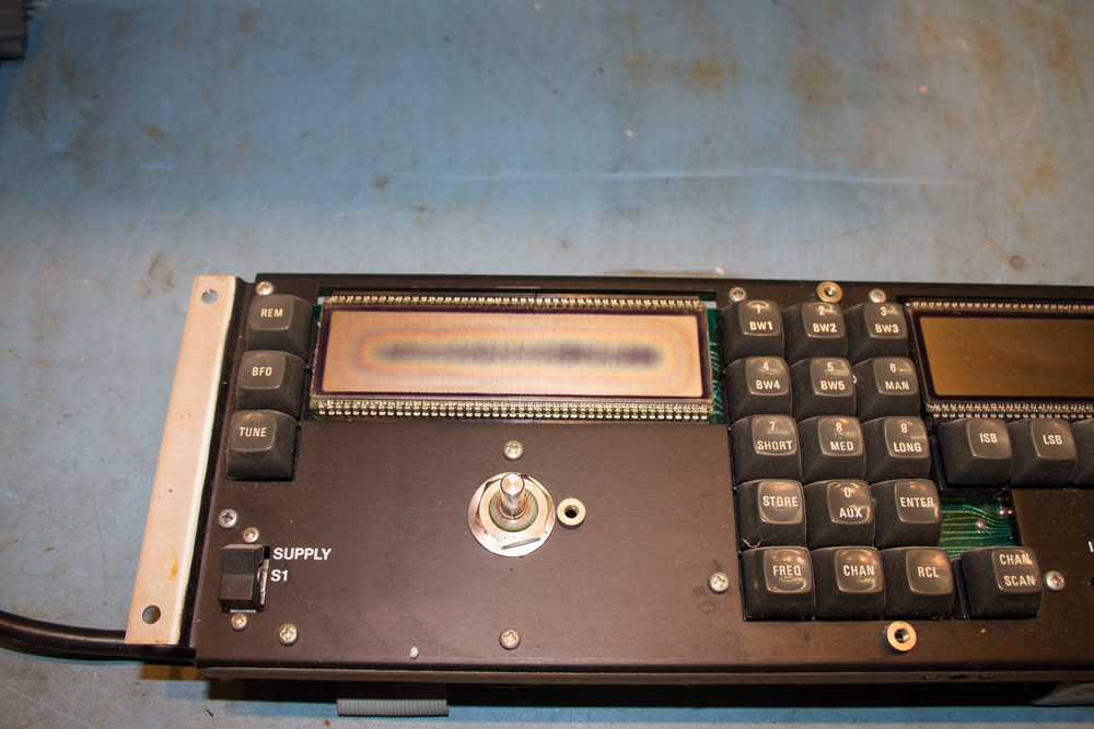
The other unit is not as bad as the left hand unit, but we ordered both replacement units and so we will be swapping out both.
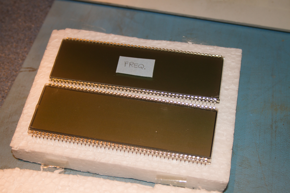
These are the brand new unit that we got from Italy.
Using a plastic spludger, these display units are really easy to remove, just applying gentle pressure to each side of the displays will simply pop them out of there sockets, try not to be too forceful here, as although you are replacing the units, you might as well try to keep them as spare units just in case….
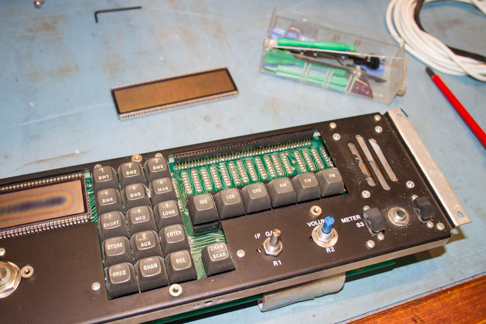
With the display unit removed place it somewhere safe and at a later time we can put these into the same packaging that the new ones came in..
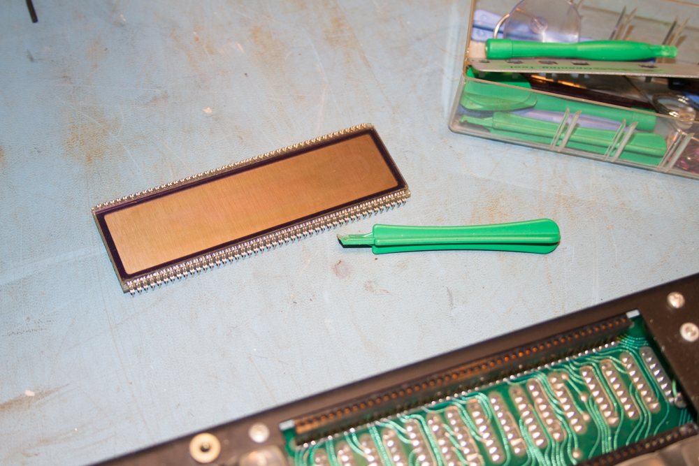
Now fitting the new displays are a little problematic, the pins are not as strong as the original versions, and will often bend when they are inserted into the sockets.
Very carefully bend the pins in a little by holding the displays carefully on their edges and apply pressure to them, I was lucky as I have a large anti static mat that makes this process not only safe, but the mat also has some give in it so that you should feel if you are pushing too much before any problems occur.
Keep gently placing the display units into place to see if the pins match up with the holes in the sockets, and when you feel that everything is right gently push them home, and try to keep them level whilst you do this as you may get the odd pin bend in on itself and if this happens you will need to remove the whole unit and using some very small needle nosed pliers, gently straighten the legs.
Owning up to this I had to do this twice before the unit seated itself correctly.
Below you can see the old and the new…
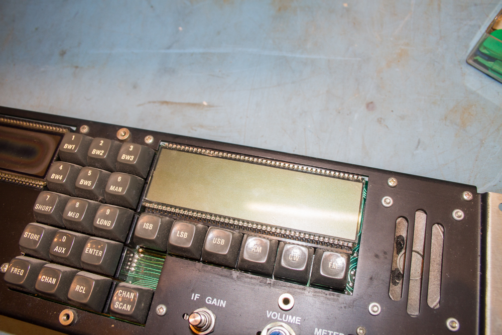
Here is a closeup of the new unit.
Next job is to have something to eat, and as Morgan was paying me for the job with a Chicken Sandwich, I insisted on it.
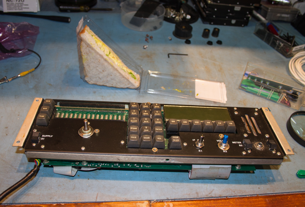
Now refueled, I need to sort out the left hand display unit, this is done the same as above with the right hand unit.
One thing that I forgot to mention above is the fact that there are no markings on the PCB of the display unit to say where pin 1 is.
Also there are no markings as to pin 1 on the new display units.
Thankfully, there is a helpful sticker to show us which is the frequency display unit and assuming that the person that made these stuck this on the right way round we hope that this is the correct way to view the display, also on the units themselves, there is a small bulge in the edge of the glass units, so we know that these should hopefully go to the left of the unit. this is good to remember if you end up having to remove the units to re-straighten the legs and forget which way round the units were.
Simply running a finger down the edges of the units will easily distinguish which side should be on the left.
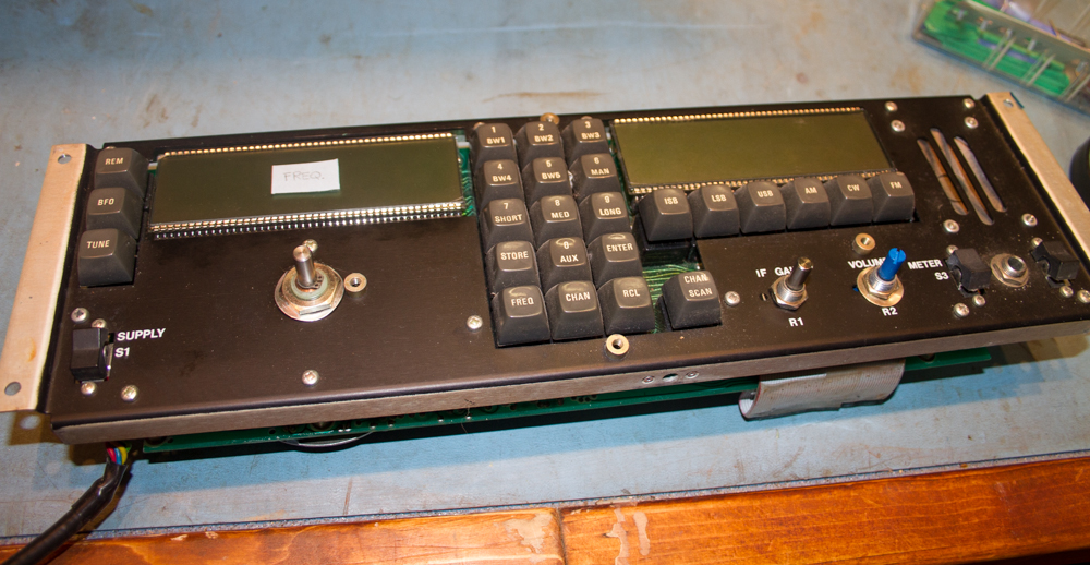
Now with the face unit ready to be reassembled, a good clean of the chassis is required, a very simple task with a nice soft anti-static brush.
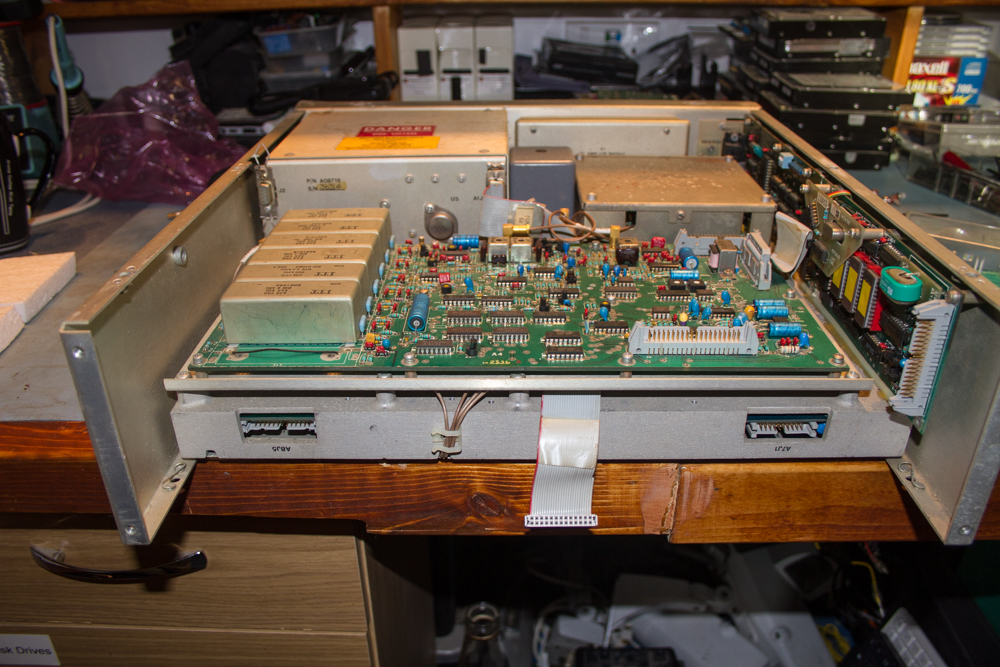
Again using the aid of a helpful Morgan you can start to reassemble the face unit. I think my Morgan is getting a little out of warranty as you get the odd gruff comment every now and then, I should have returned mine before its warranty ran out, never mind…
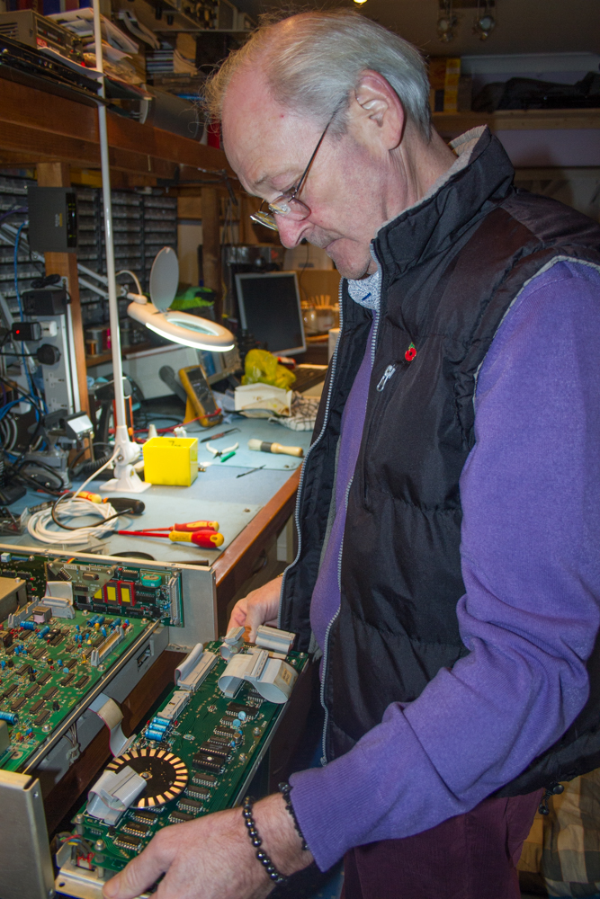
To replace the face unit you just need to do everything in reverse, quite a simple task really…
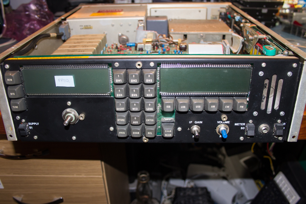
Before doing too much work, it is best to switch the unit on at this stage and check that the displays work correctly. Make sure that all of the characters display properly and all the mode indicators work, if anything does appear to not work right, make sure that none of the pins are bent and not making contact, thankfully in our case this was not an issue.
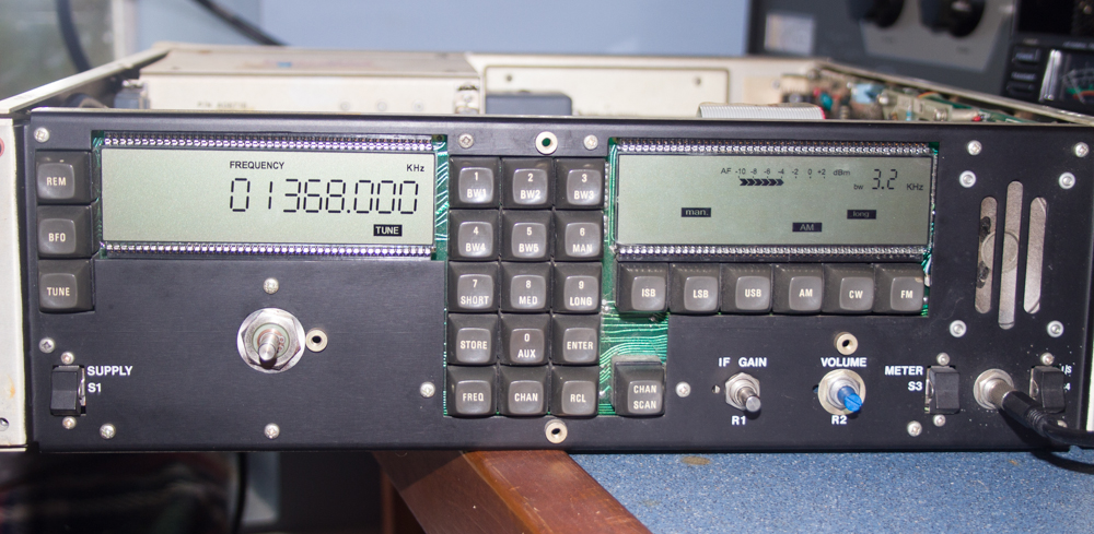
Now with all the tests done, we can start to tighten up all those bolts and reassemble the pretty bits…
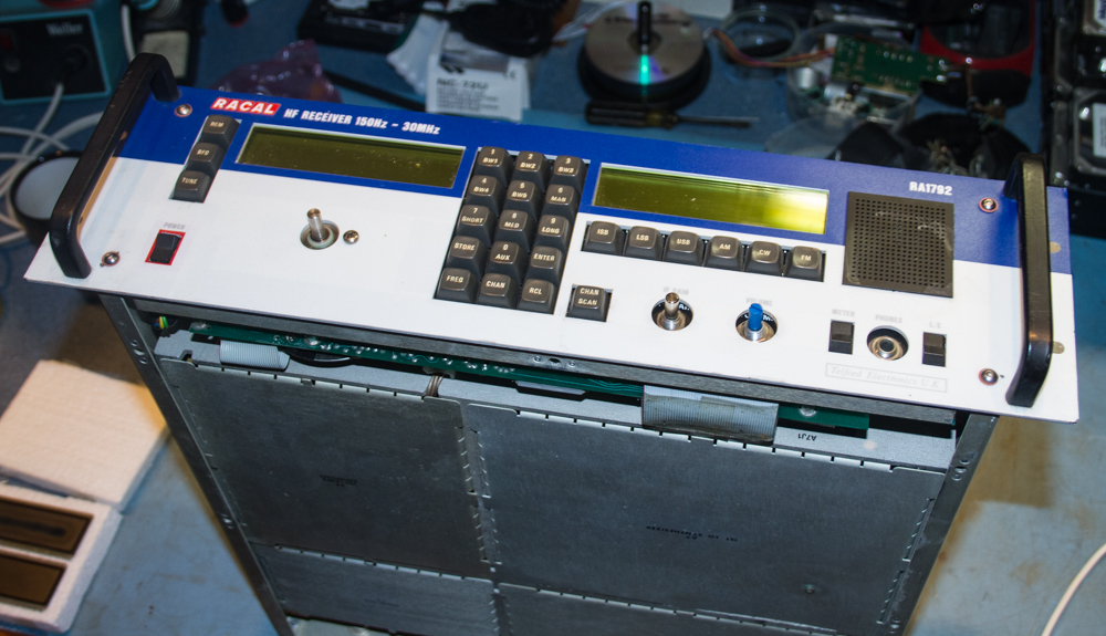
The front unit is reattached with the single screw under where the VFO knob fits.
Screw the four face plate screws back in.
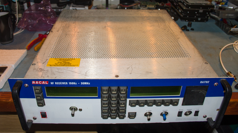
Replace the top and bottom covers at this stage.
Refit the Main VFO Knob and make sure that you do not over tighten the clamping screw, once done, replace the top cover to hide the screw.
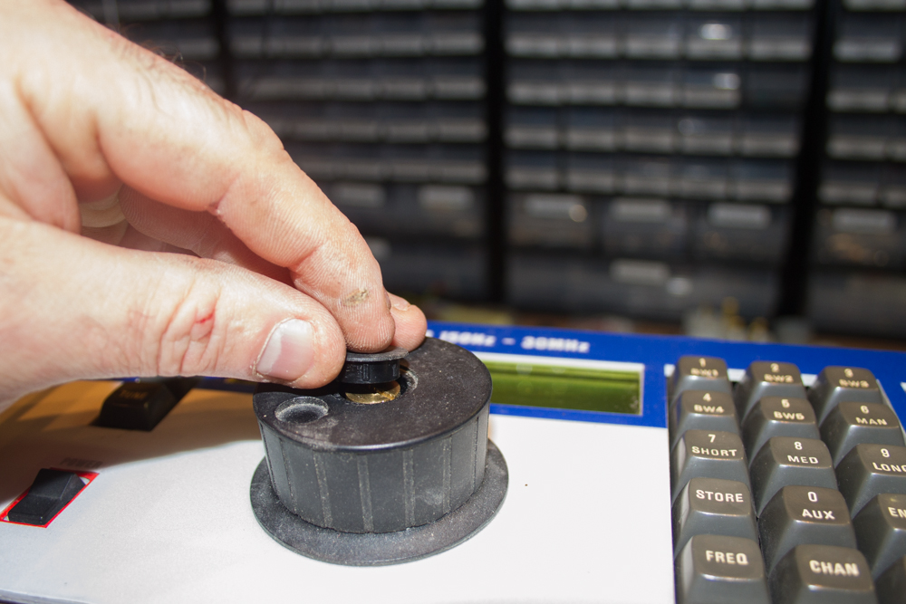
Do the same to the two smaller knobs…
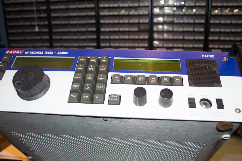
The old display units can be placed back into the packaging that the new ones came in and then hidden away somewhere, or thrown in the bin if you would prefer.
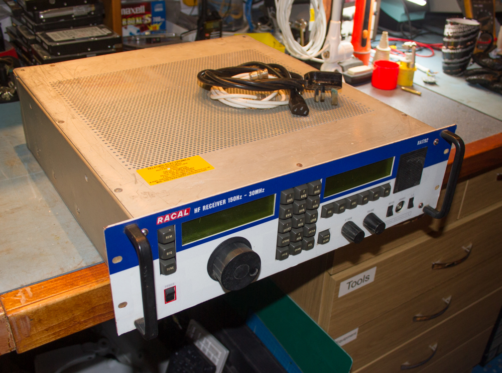
The finished unit ready to be taken home and played with.
So with the receiver all tested and checked out, and by the way the filtration on the Racal is fantastic, a lot better than some of the newer Ham Radio transceivers, so anyway we have a happy Morgan!
On top of the receiver is an old oscilloscope that I wasn’t using, having way too much test equipment nowadays, so he said that he wanted one so I donated it to a worthy cause, need to clear out most of my test stuff anyway, and it saves taking it to the tip.
So for the small cost of the display units, about 1 hours of fitting, and a further 1 hour testing and realignment, our Morgan has a working receiver, another toy for him to listen to aircraft on!
