I have in my collection of great Vacuum Tube Radios and quite large collection of Drake gear with I love, I briefly lent it to a very good friend to have a play with and he spent a lot of time tuning the gear and also adding to it with some truly rare and lovely mint examples of some stunning radio gear, I owe him so much for what he did. But I now have these back in my hands and soon I am hoping to have the gear all laid out and connected to antenna’s and available to operate as they should be.
I have always wanted to get my hands on some Collins gear, every time you start talking about old radios, then name Collins is always there and when you meet people that have owned Collins, they are always singing the praises of what must be the ultimate equipment when it comes to Vacuum Tube radios.
I never thought that I would ever be lucky enough to own any Collins equipment, and I know that it is only one item now, but I am hoping that more may appear as time moves on, but I never expected to get my hands on an item so mint as this one.
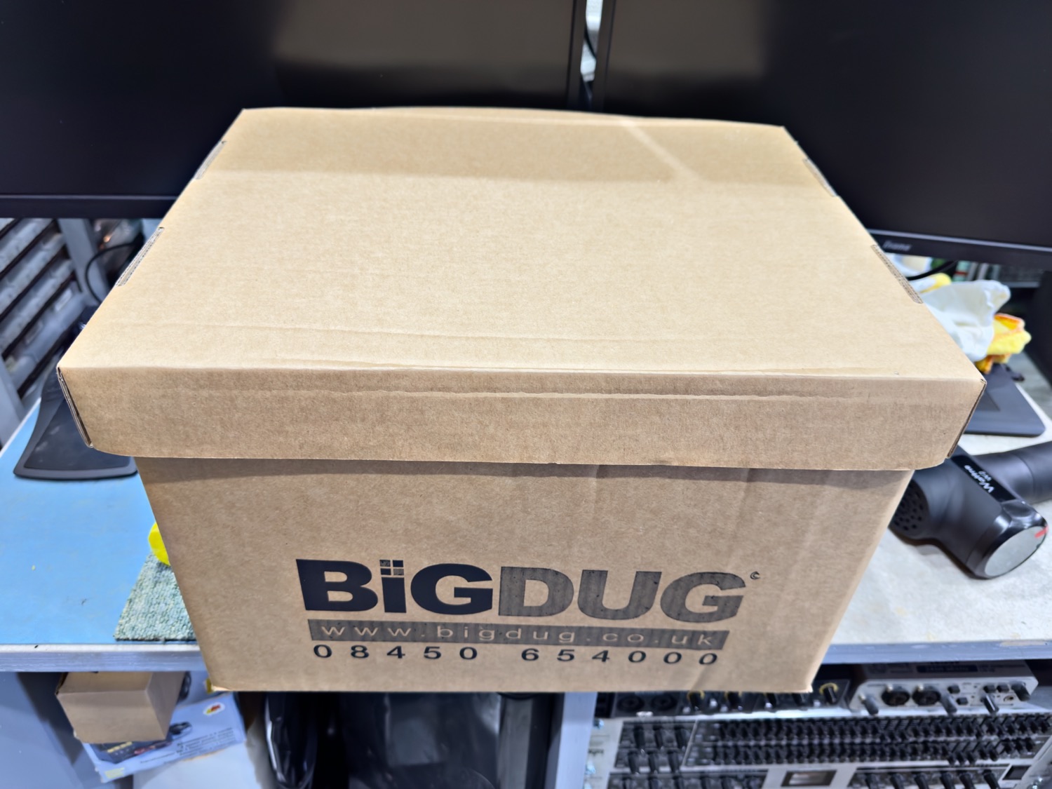
A Box with Treasure Hidden Within
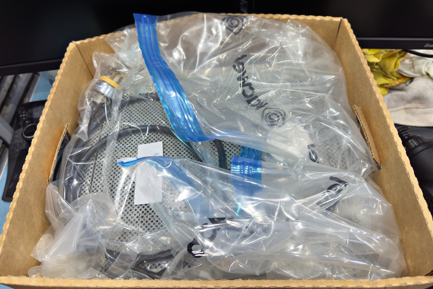
It came in a removals box of the type that offices us, and inside was one of those vacuum bags that you get for shrinking down your clothes, but at my first glance I could tell that this was something truly beautiful that will not need a lot of work to get working.
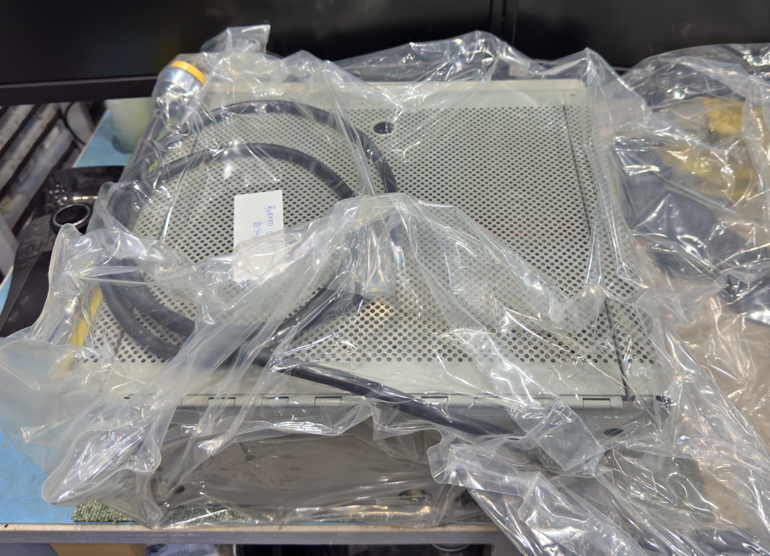
Out of the Box is a Vacuum Bag with something Very nice inside.
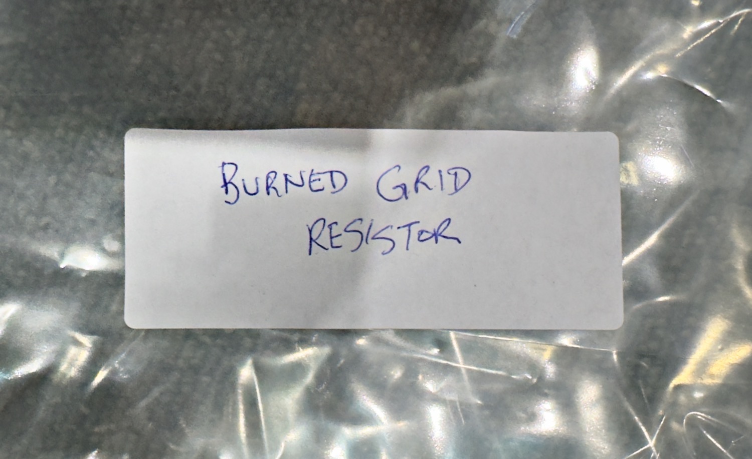
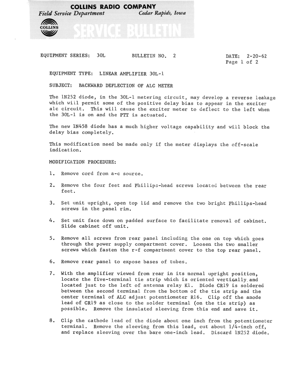
It has a minor problem - Burned Grid Resistor.
And like most stuff that I seem to get my hands on there is a little problem which I did know about before I received it, apparently it was in use and a wrong antenna was selected which caused ‘Burned Grid Resistor’, this will hopefully be an easy fix providing the what the internals are like.
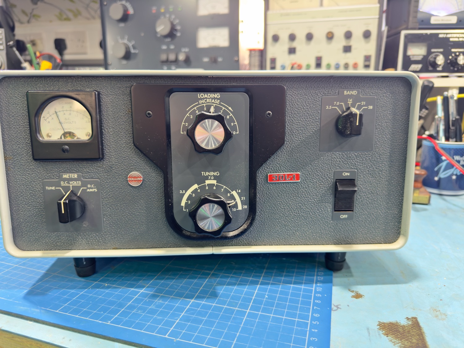
I must admit that when I first put this on the bench my jaw was bouncing off the floor. It is about as near mint as you can get, this was made 5 years prior to me being born and it certainly looks a lot better than I do.
Besides the dust and the odd mark that can be cleaned off, this is one Mint Amplifier.
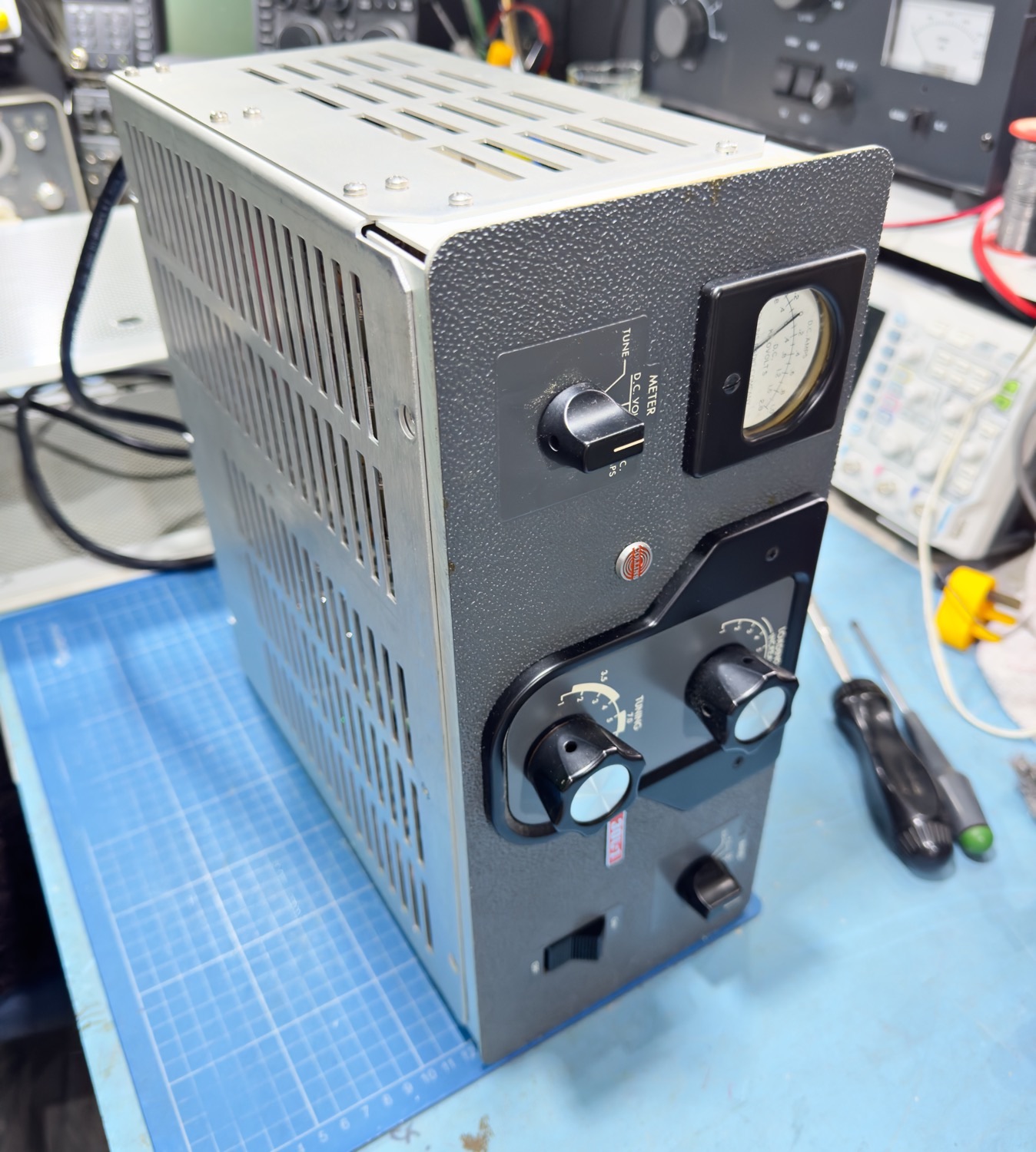
This RF Amplifier was made around 1960 and it looks newer than one you would get today.
No Scratches or Signs or wear and tear.
The View from the Top.
I am truly amazed at the quality of this old beast, it is not a large RF Linear Amplifier, at best you will get 1000 watts out of this if you look after it, and it will last a lifetime if you keep it to 800 watts ad look after it, and of course make sure that you have selected the correct antenna hi hi. But I have never seen Heathkit, Henry or even Drake equipment of the quality of this item.
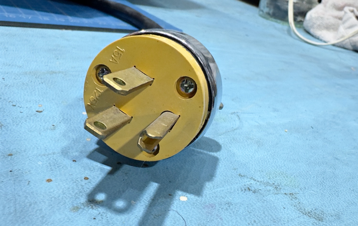
This is a Collins piece of kit, so I expected it to have an American 120 volt plug on it. This is not a problem; I have a lot of 120 volt transformers here that are both filtered and smoothed as I have a lot of gear that that still runs on 120 volts.
A 120v American Plug.
Lets have a look inside.
So it cannot be helped, I am going to work on it anyway, so I might as well get inside the outer case and see if the inside is as good as the outside.
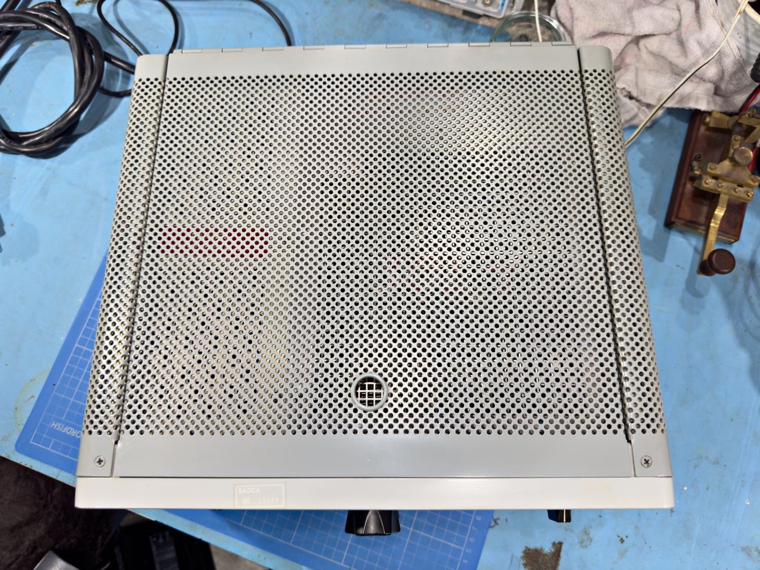
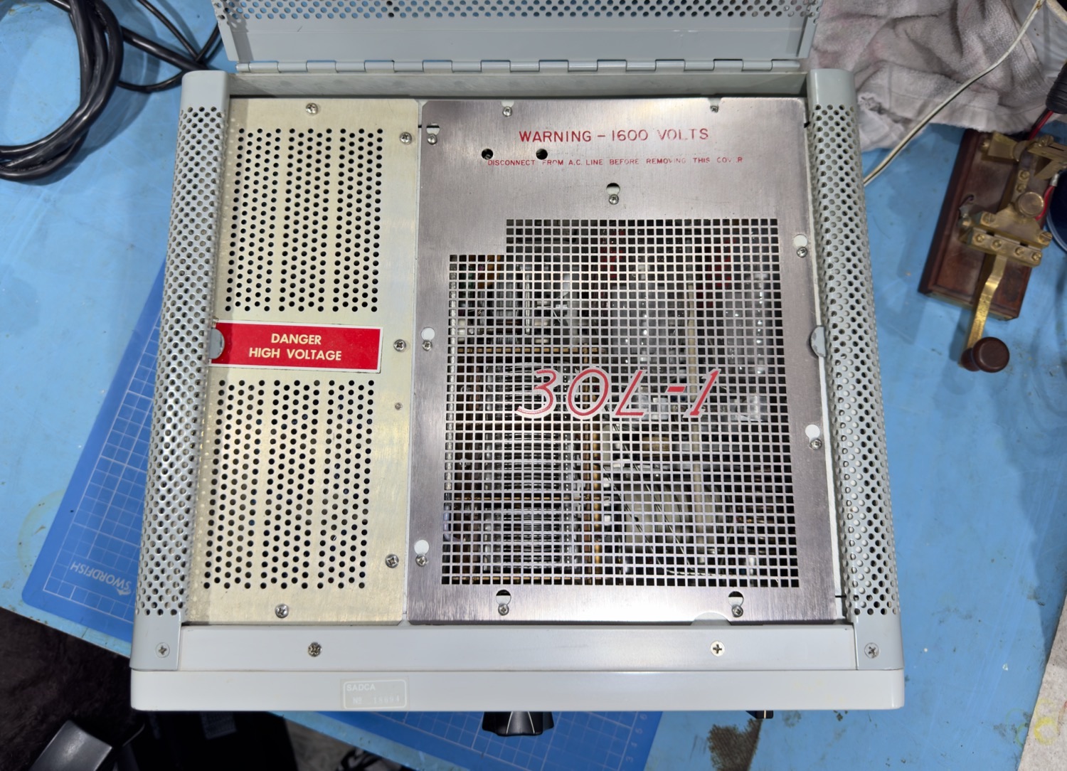
Lift the Lid and it still looks great.
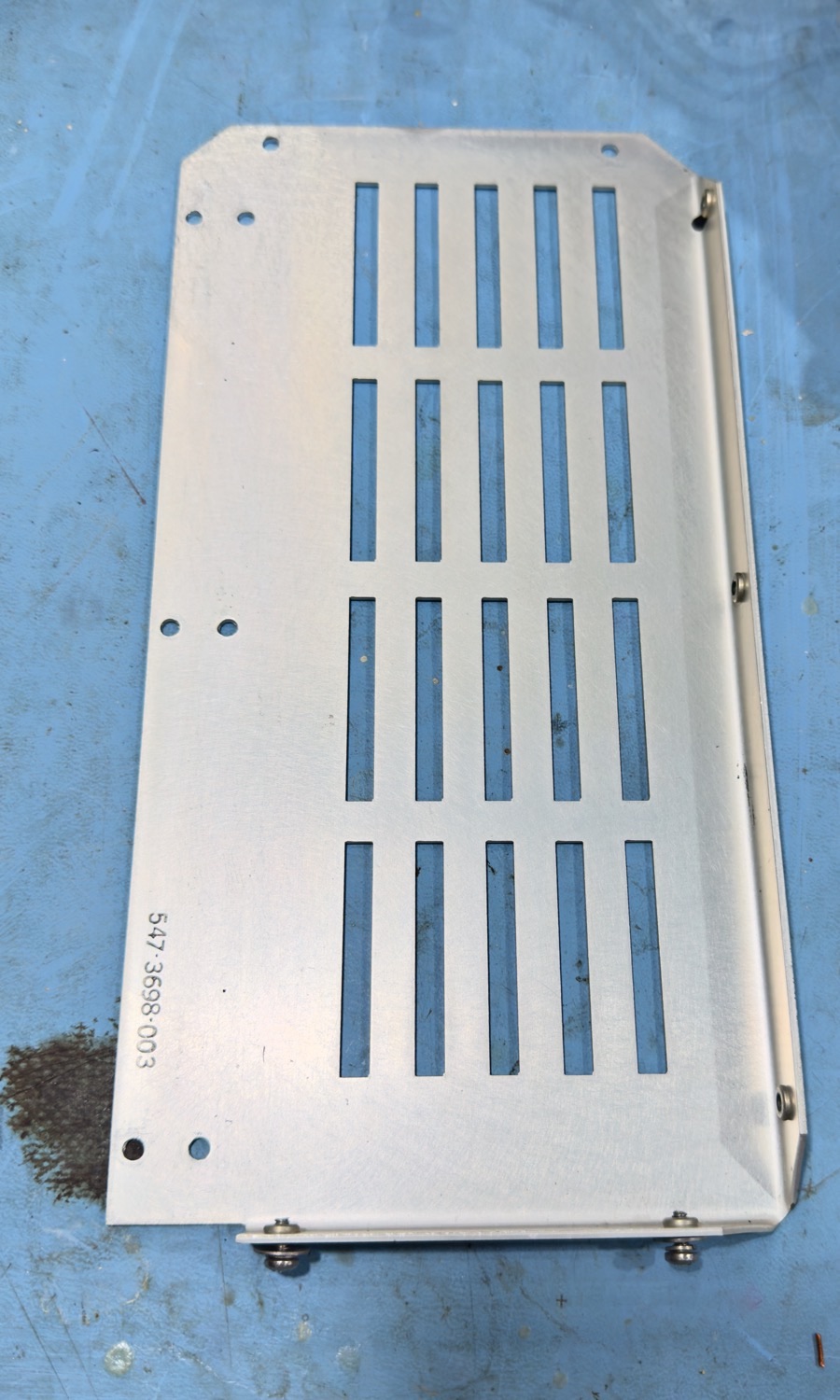
It is the small bits that put Collins ahead of most other manufacturers. So we have a shield that is not only a RF shield, but it has holes to let the heat out, and what does Collins do – The go and put the model number on it and add a bit of colour, this shield will be hidden for nearly all of its life if the amplifier is looked after correctly and yet they add a bit of text to just emphasize that this is a quality piece of kit, and defiantly not you normal cheap amplifier.
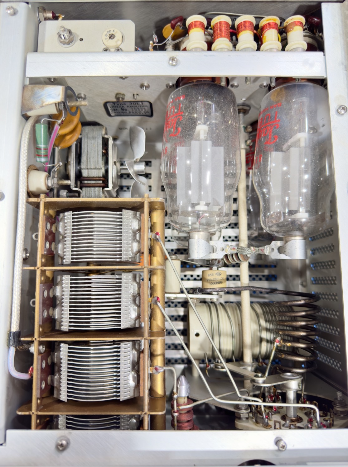
A Work of Art.
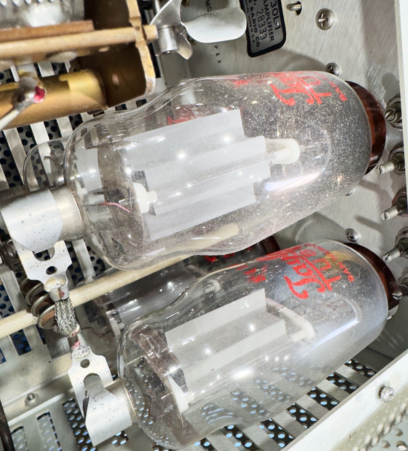
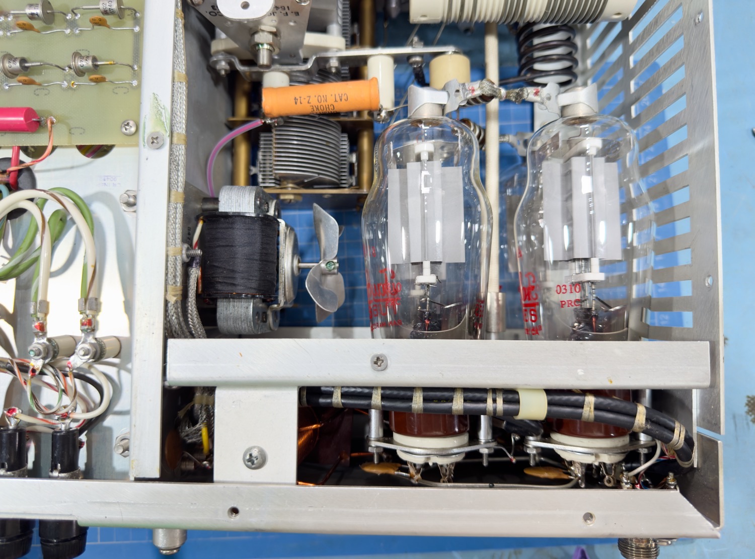
I have never been a fan of vacuum Tubes being mounted on their sides, it always causes a problem with heat, and you will normally find that the upper tubes will quite often degrade a lot faster than the ones below. This is the only problem that I have with this design, the more that I look inside this amplifier the more I like it, besides the dust it looks brand new which will hopefully mean that this will be a very easy restoration, well fingers crossed!
Wherever you look, you cannot help but smile.
The tubes look like new, no signs of overheating.
I was thinking that I would need to place an order with Penta Labs to get a set of new tubes, but after looking at them I think that can wait to later as I just might get away with these as they are looking very good, but I will not really know until we apply some power to the unit.
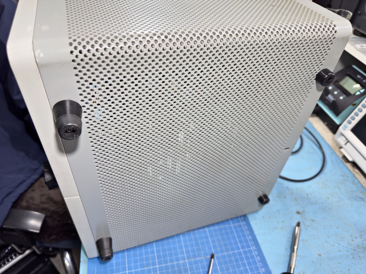
Now the challenge, how do I get into the box, I always like to think that getting inside a case should be straightforward but as I have always learnt, when you are given something new there is always going to be a spanner thrown into the works.
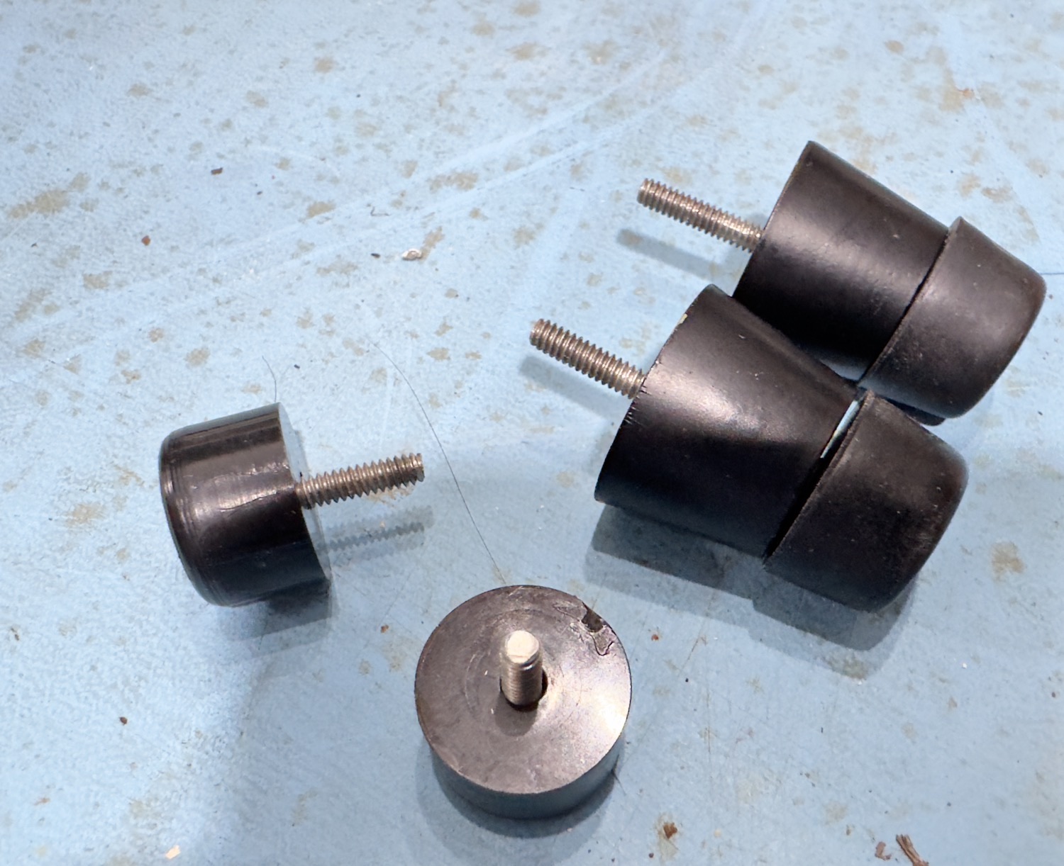
I started with the underside of the case, there are four feet that look as though they are screwed into the chassis, so I removed these and the screw in the middle of the rear of the case.
I removed the four feet and the screw at the rear of the case.
The four feet and some very long screws.
The Screw with all the washers from the underside of the case.
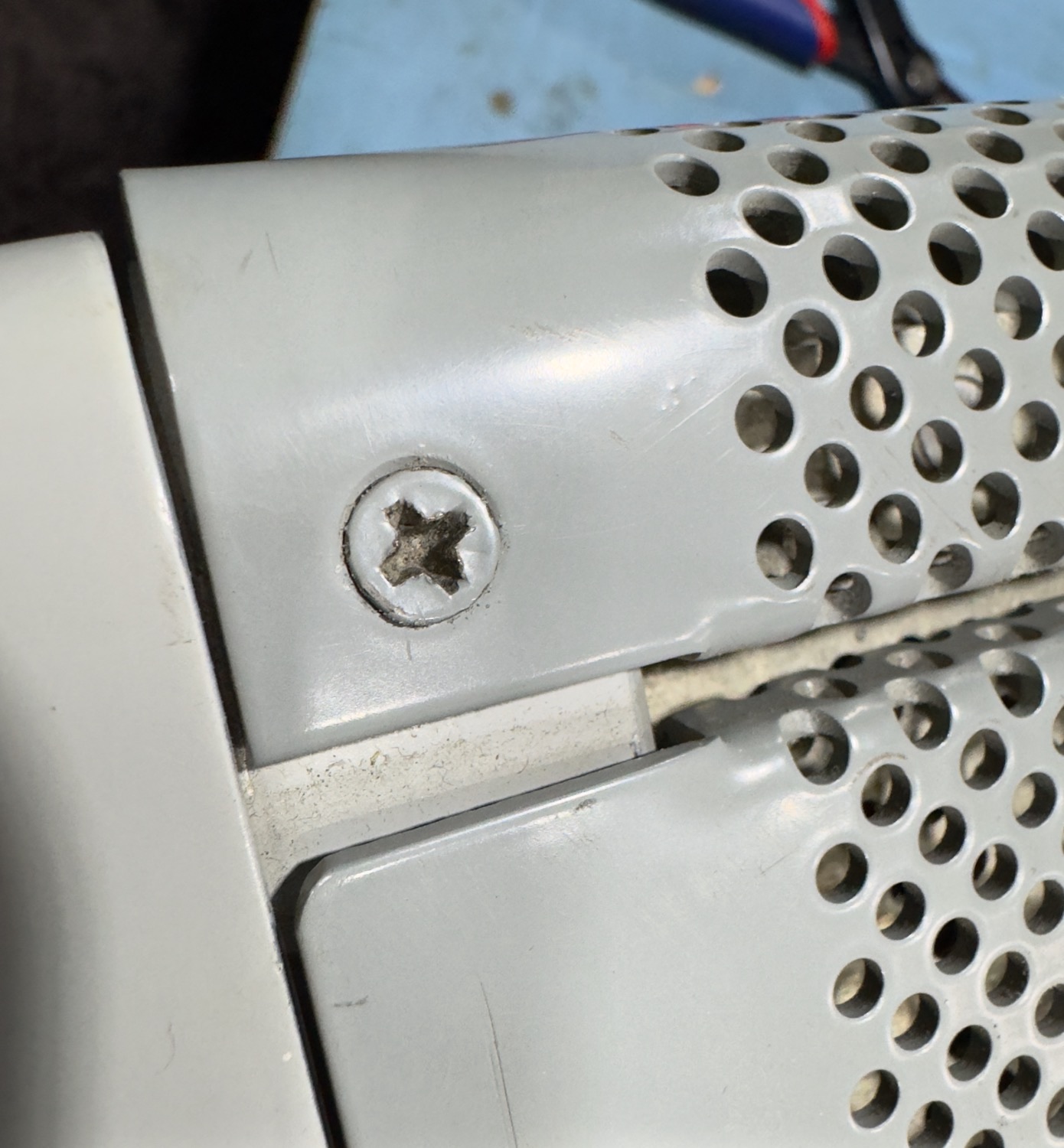
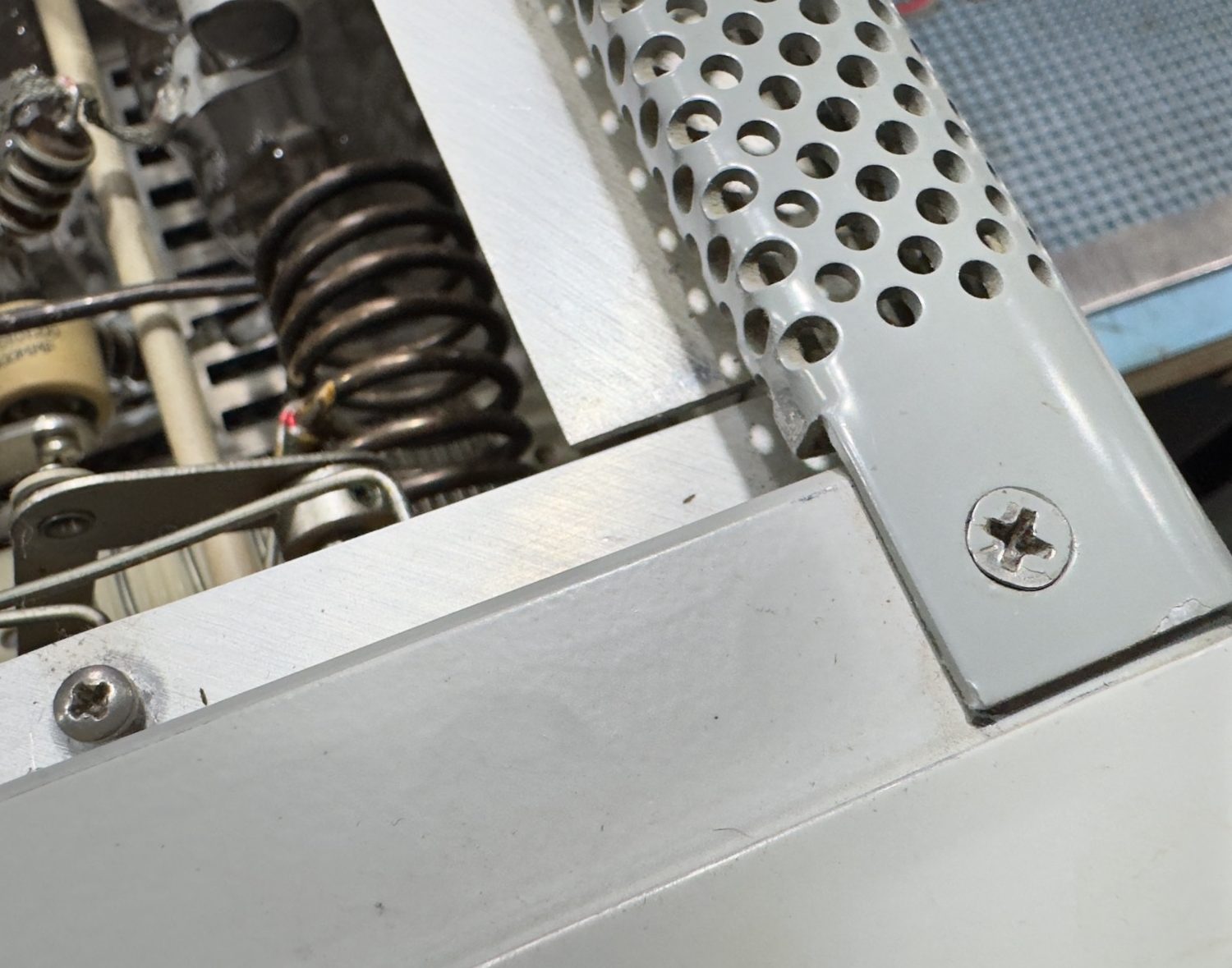
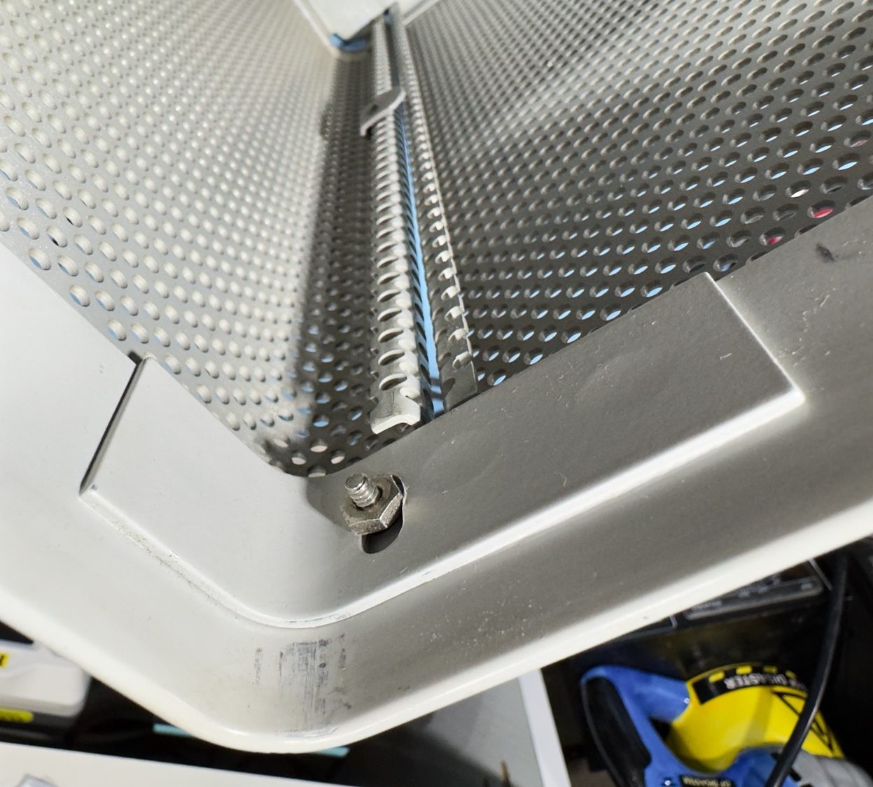
It was all going well until I flipped the unit over and started to remove the two screws near to the front of the case, I originally thought that they were captive screws when they seem to loosen up but I could not remove them, I then had a better look and you could just about make up that they had nuts underneath the chassis but in a very small gap that I have no idea at this time how I will be able to tighten them up, but I am sure this will become apparent later.
The Screw on the left hand side.
The Screw on the Right...
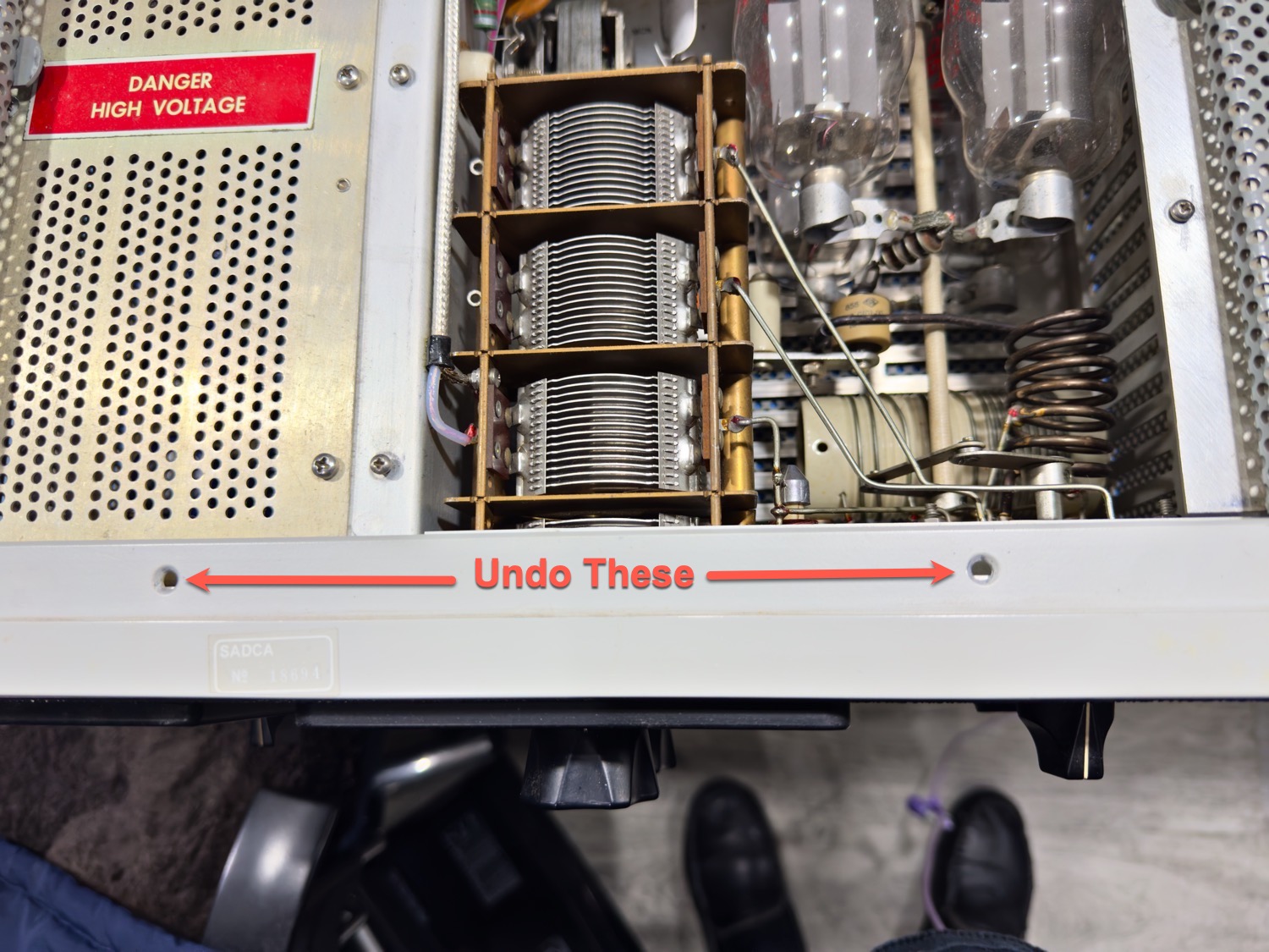
Okay I got it wrong! Maybe a good time to read the bloody manual like I should have done in the first place. So, Lift the lid and remove the two screws at the front of the unit and not the two that I first guessed, hopefully I can re-tighten these later.
Take these two screws out to remove the chassis from the case.
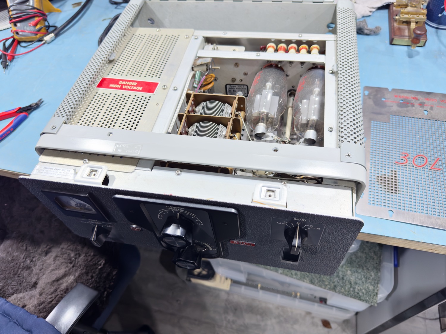
Now as I had previously removed the feet and that bolt from the middle of the underside, it is now a simple case of gentle pulling the unit out, once out I do have a small problem which it the mains cable and that annoying large round American Plug socket, but as I have a little bit of space here I will pull through just enough of the mains leads so that the plug does not do any damage to the case, and just to be on the safe side I will cover the plug in a cloth and then also make sure that it will not slap against the case.
And ever so gently she get released from the case.
Now that she is Out we can start to plan the next stage.
And before I forget I can now tighten the two screws that I undid before.
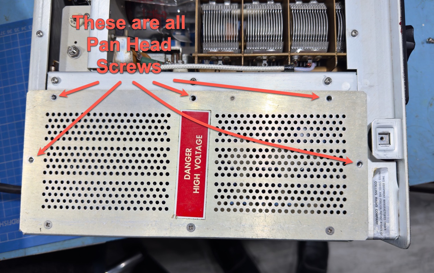
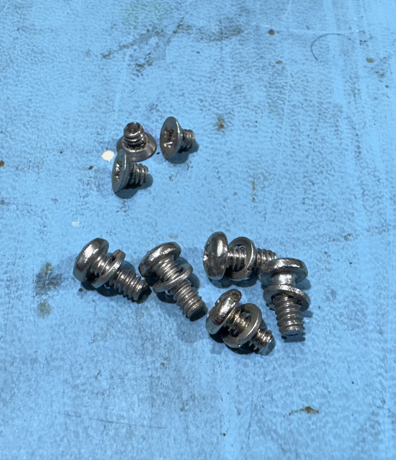
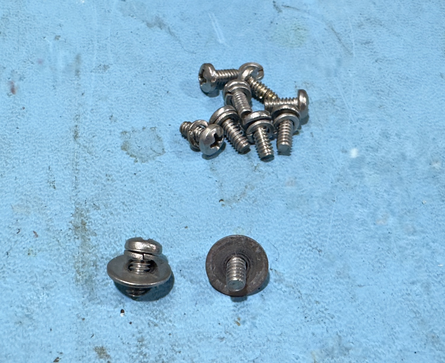
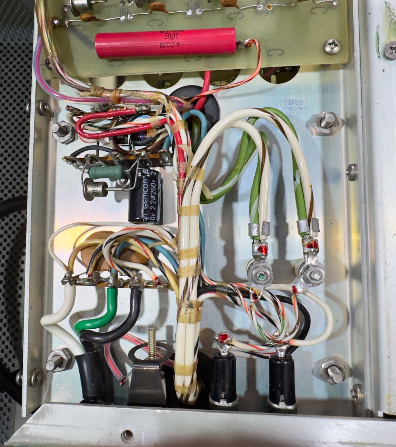
The first thing that I want to look at here is the regulator stage and to also see what the Capacitors look like; I looked on YouTube before hand and there were a few horror stories out there. So, I need to remove the cover with the warning on it, but you need to make a note of the two different types of screws, Pan Heads (5) and Countersunk (3) screws.
Remove the 5 Pan Head screws first and put somewhere safe.
Make sure that you keep these safe, somewhere.
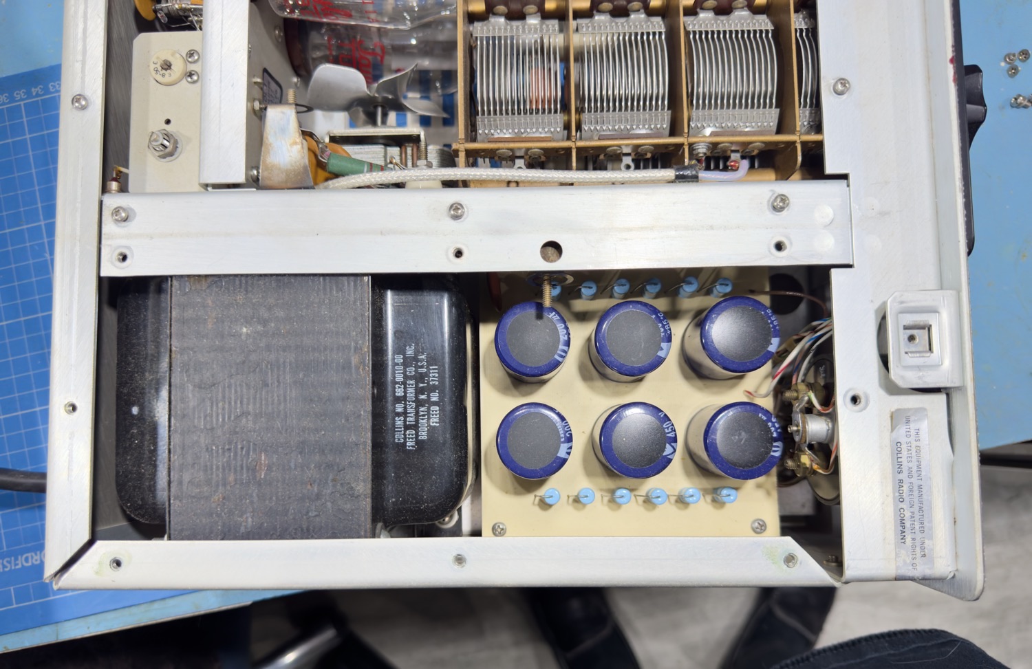
That's Not exactly what I was expecting to see.
I am really enjoying this, unlike a lot of old radio’s, I would normally have a few scars by now from sharp edges or rusty corners, but this is great, all the metalwork is well smoothed and easy to touch without going Ouch!
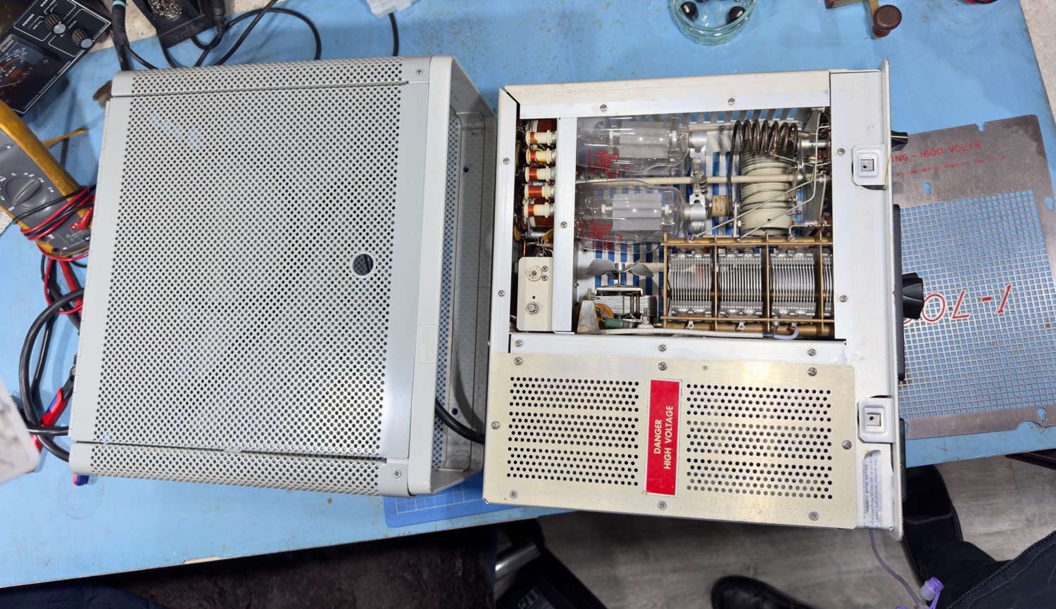
Collins 30L-1 on it's side so that I can start to remove all the metalwork!
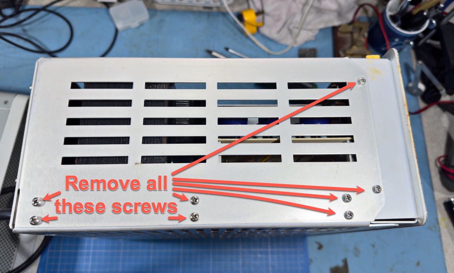
All these screws are the same, but keep them in a safe place whilst you are removing these plates, I will screw them back into the holes when I have removed this end plate.
Screw Removal Time - Keep in a Safe Place.
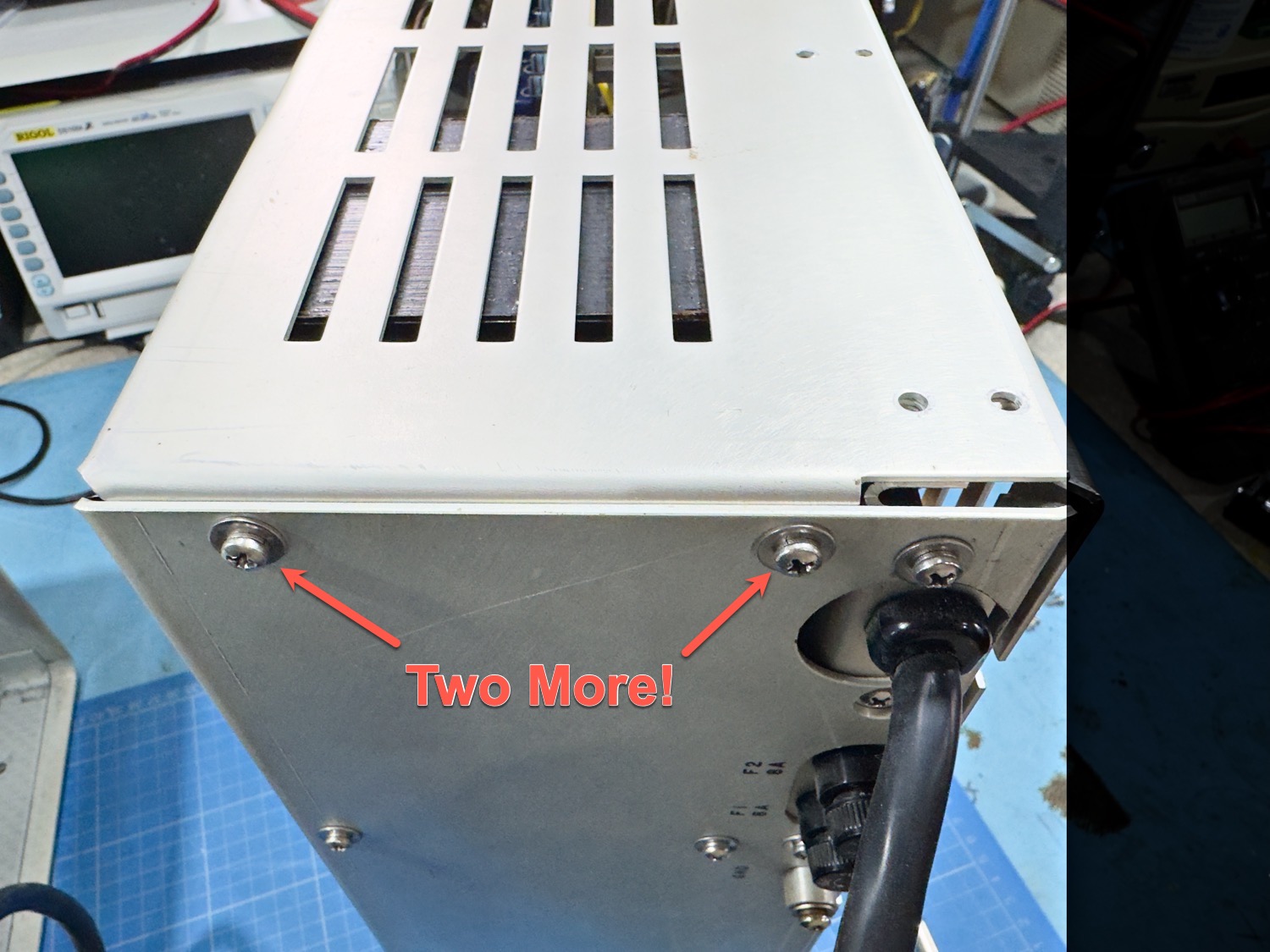
Two More Screws to Remove.
Theses are all the screws that hold the end plate in place.
Make a mental note that the last two screws from the edge of the plate are different, and make sure that you do not mix up the washers, with all these screws removed you should be able to remove the plate and set it aside.
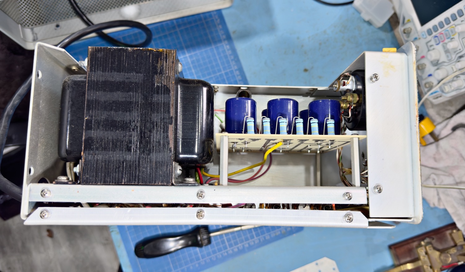
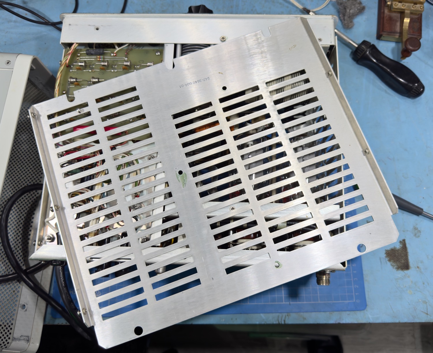
The end plate removed.
This is a work beauty, I was not expecting this.
First Of 0 You will see from the above photo that I have placed most of the screws back where they came from, I have done this for the main reason that I have a horrible feeling that even though this is a very pretty amplifier I have a horrible looming presence that I will come across something that will delay the rebuild, fingers crossed this will not be the case.
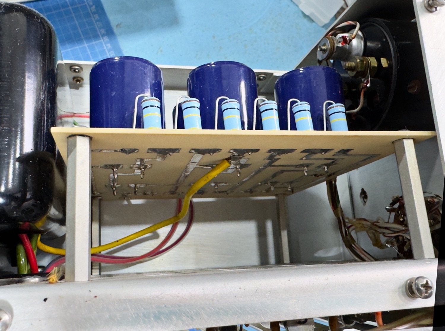
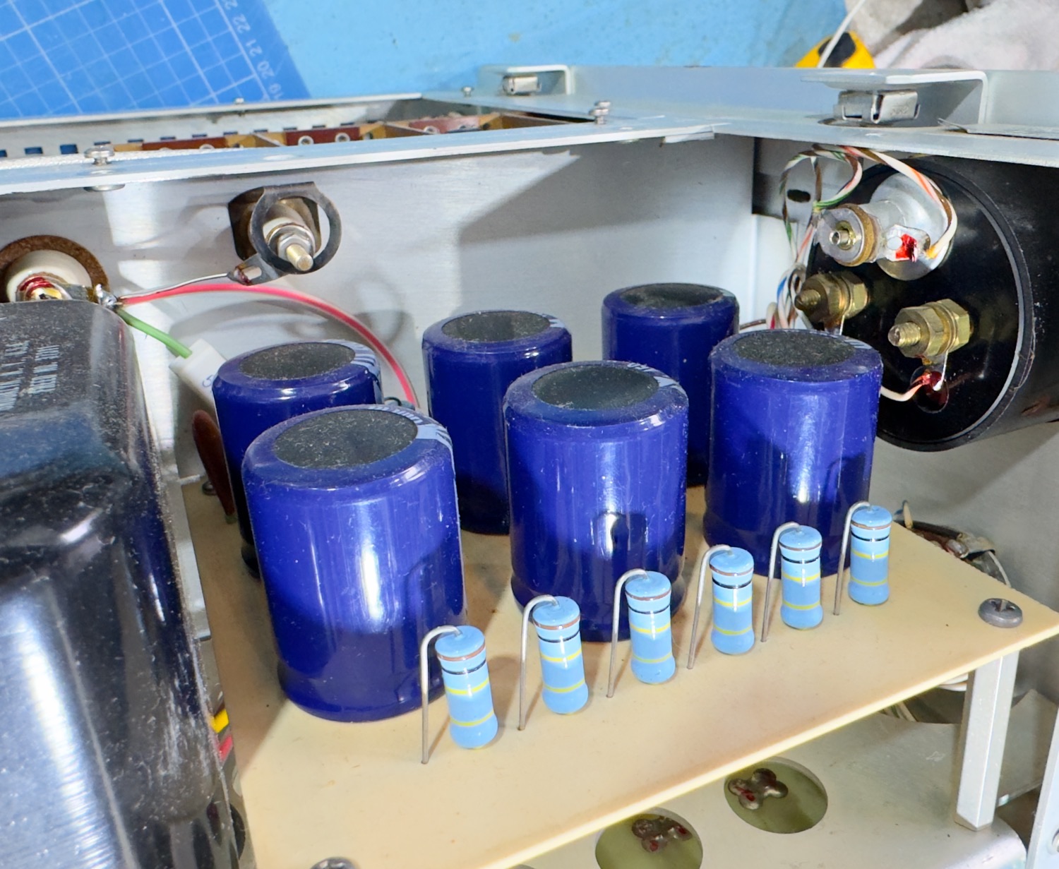
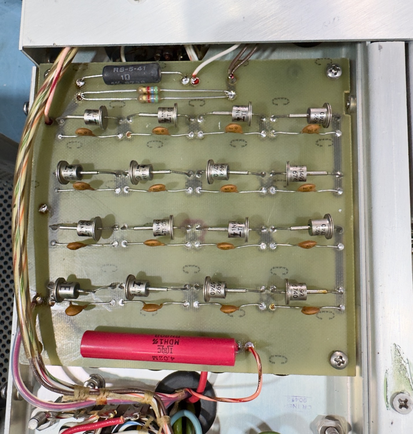
I am presuming that this is an after-market modification, the images that I have seen on the web has shown a few horror stories when it comes down to this stage, but this is beautiful and very well done, I will at a later stage come back to this and test all the capacitors anyway just to be safe.
A closeup look at all the smoothing caps.
Whoever did this it is a very neat job.
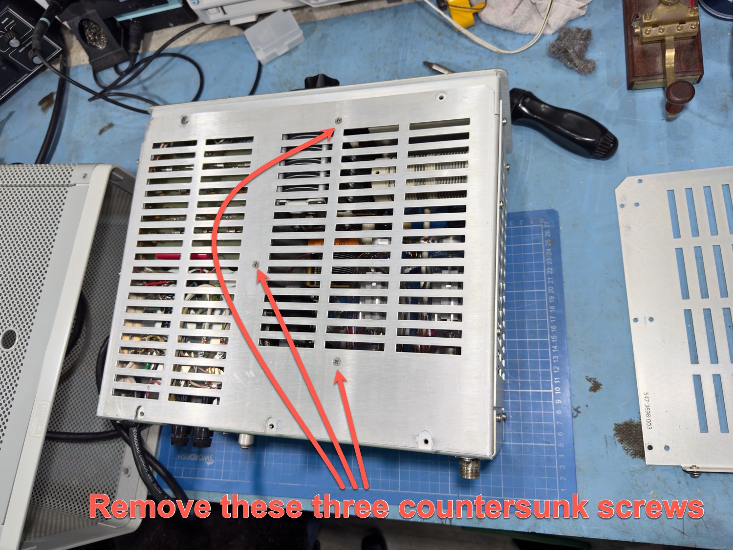
When you have finished ogling the pretty bits above, we will need to turn the amplifier onto its head and take a look at the bottom cover. On the base side it is held in place by three small countersunk screws that once removed will need to be placed somewhere safe.
Now Remove these three 'Very Small' countersunk screws from the lid.
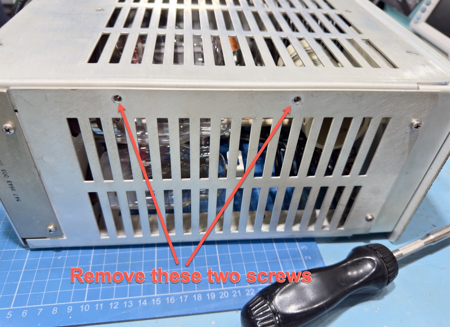
I then removed the two screws from the side of the unit to release the plate on the bottom to hopefully get a good view of the physical state of the valves.
Remove these two screws to release the bottom plate.
Put the Screws back into where you took them from to save them from being lost.
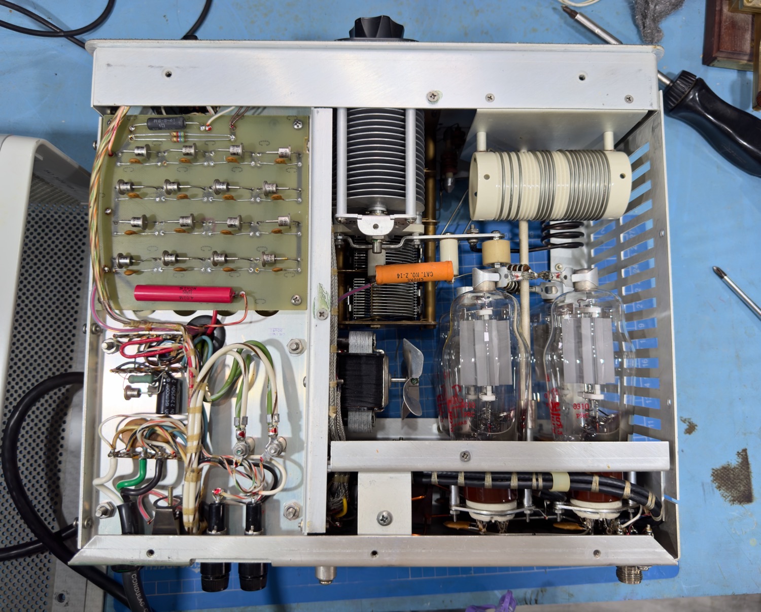
This is one very pretty amplifier.
I know that throughout this tear down I have gone on about just how pretty this amplifier is, but very really in old vacuum tube Linears do you see this level of quality, someone who put this together has really cared about what they did here, I wish all old Linears looked like this, and I cannot wait to see what the rest of the gear looks like. This is basically Collins stating that back in the 1960’s that this is quality!
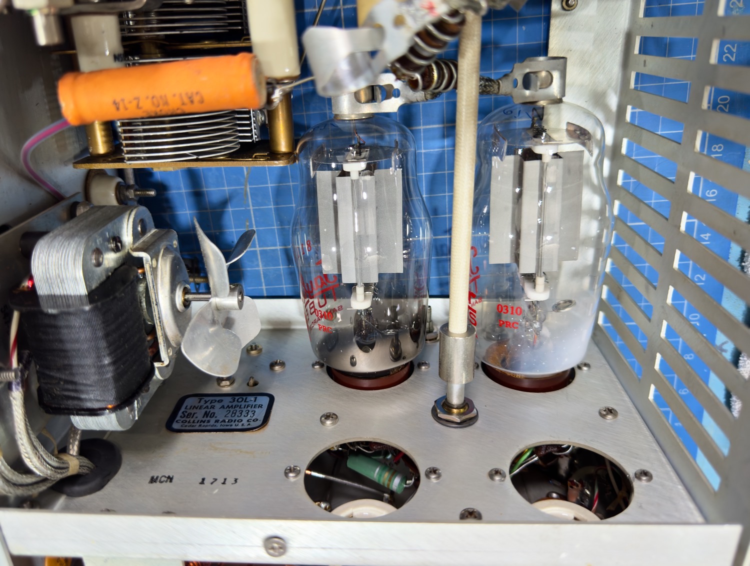
Collins 30L-1 RF Linear Amplifier RF Deck
It is at this stage that I think that I will remove the tubes one at a time, give them the quick overview and look for anything out of the ordinary.
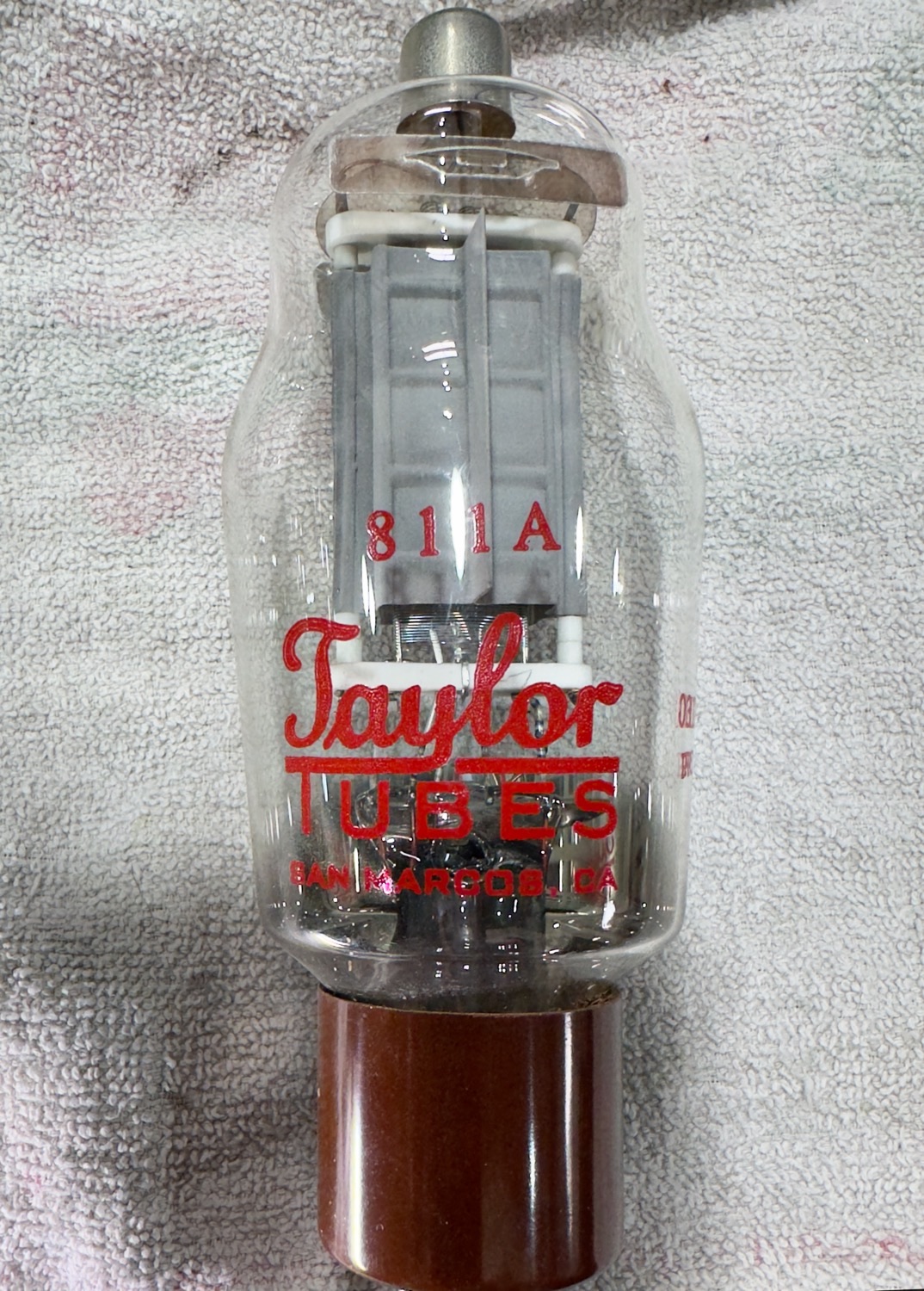
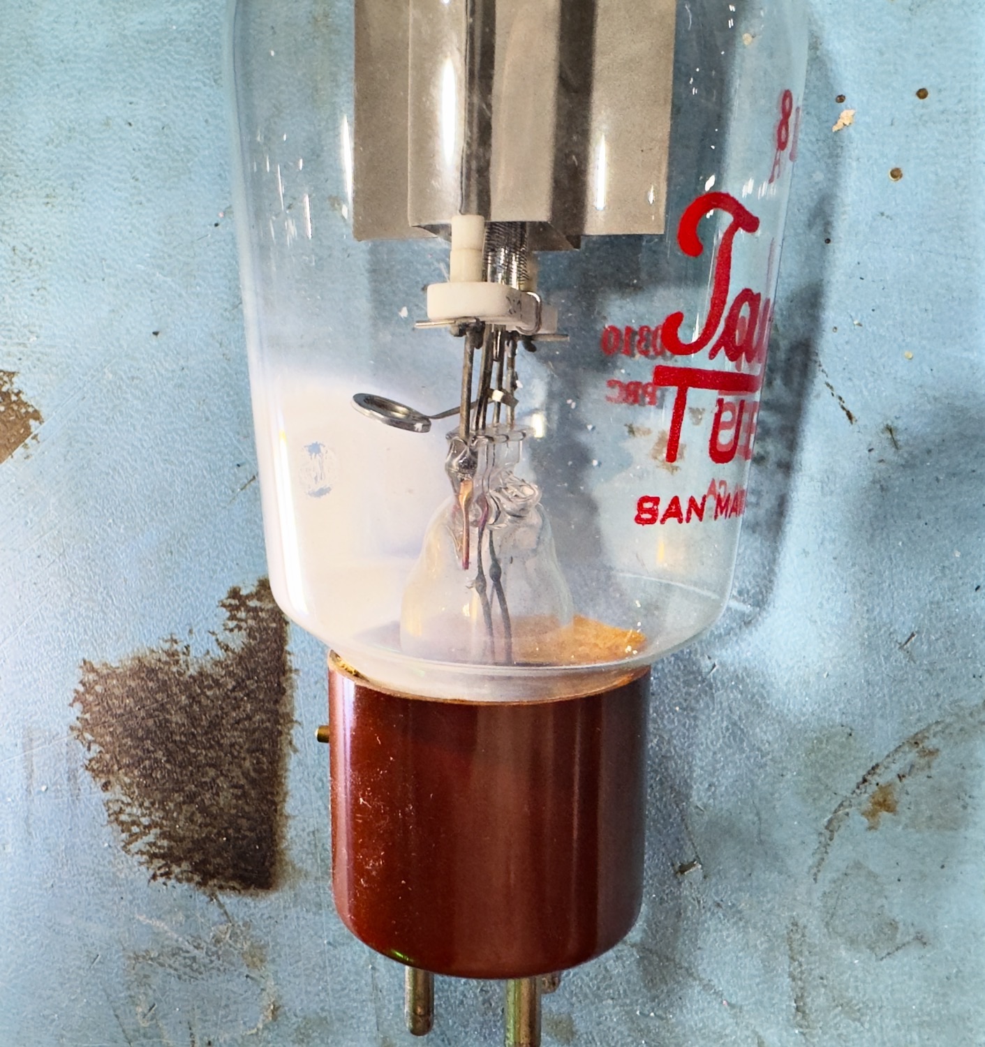
The tubes at this point look to be in good order, I will take them out and keep them in the same order that we remove them so that they ca go back where they came from. To release each tube you just release each of the caps by gently by releasing each cap from the tube, and these are 4 pin vacuum tubes, each tube will have a small pin that sticks out of the base, just make sure that these go back in the same way that they came out.
These caps can be removed easily by just compressing each cap to loosen them.
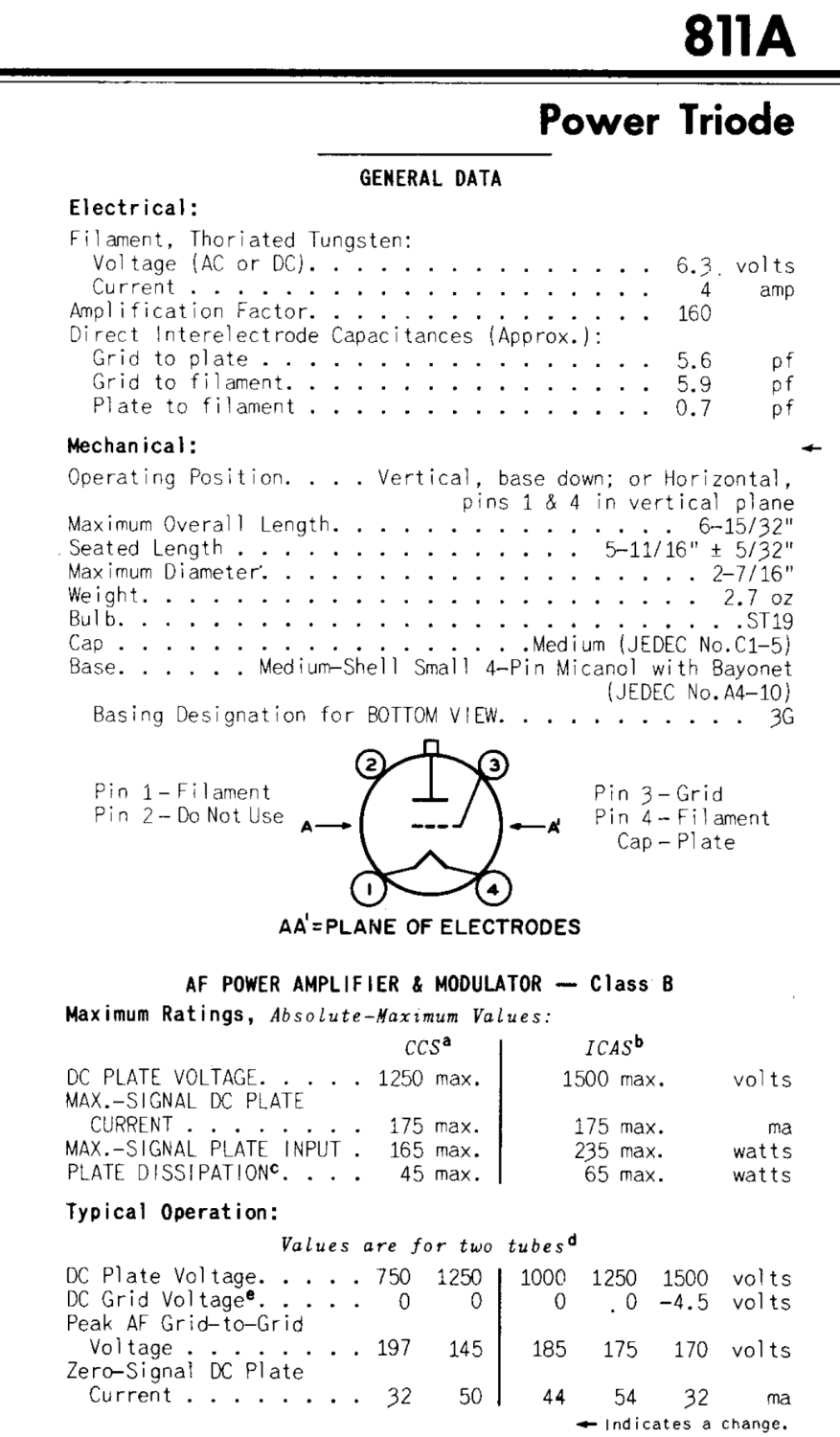
Taylor 811A
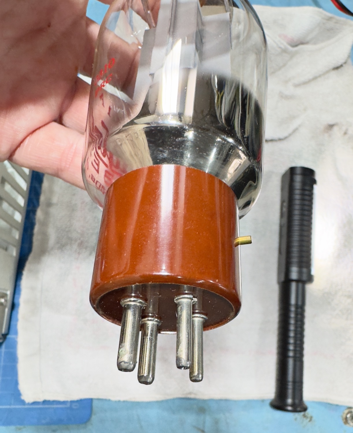
Taylor 811A Base showing the pin on the side of the base.
The tubes at this point look to be in good order, I will take them out and keep them in the same order that we remove them so that they ca go back where they came from. To release each tube, you just release each of the caps by gently by releasing each cap from the tube, and these are 4 pin vacuum tubes, each tube will have a small pin that sticks out of the base, just make sure that these go back in the same way that they came out.
See Datasheet Below.
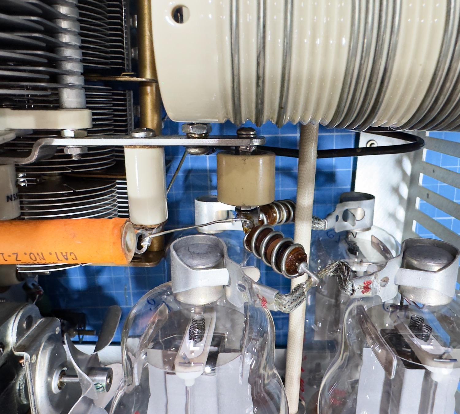
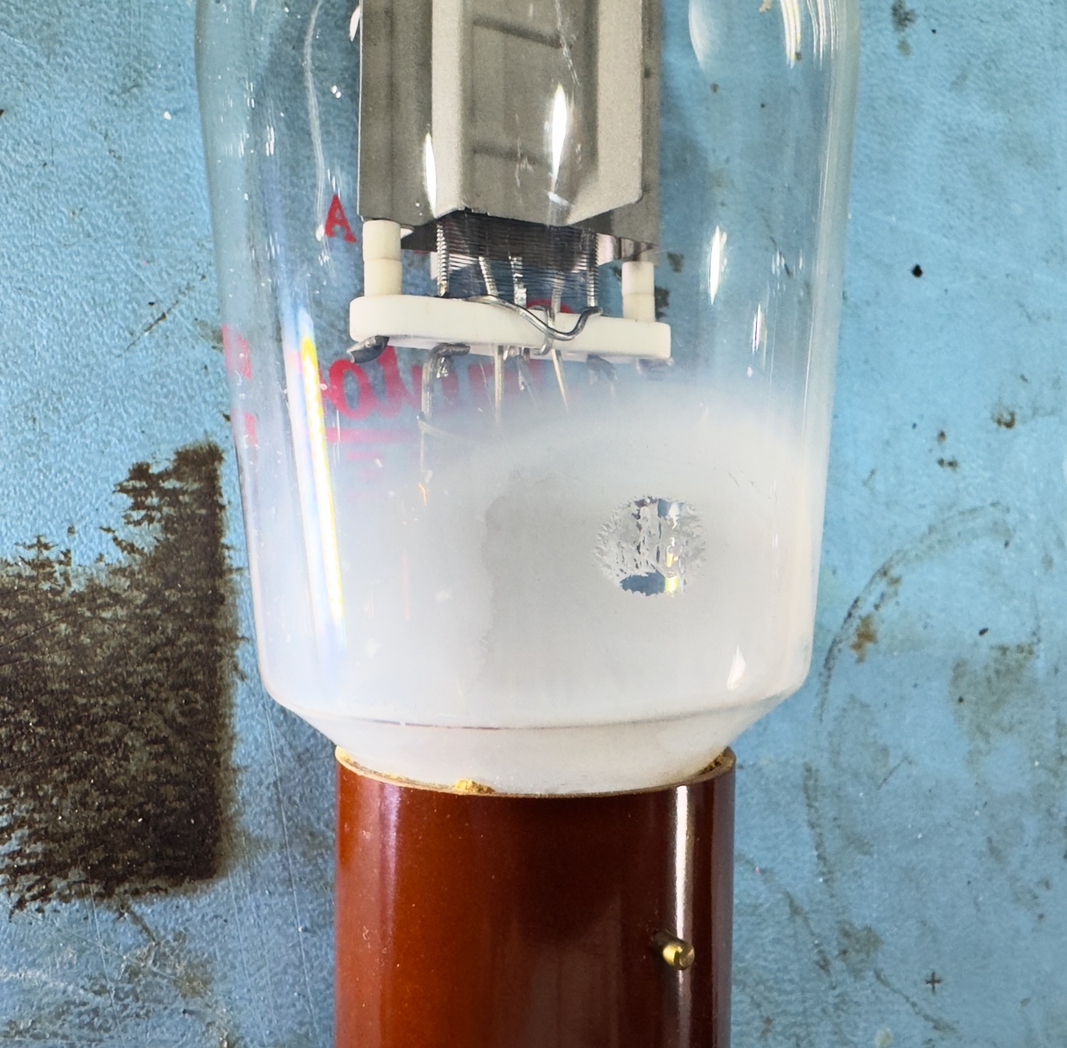
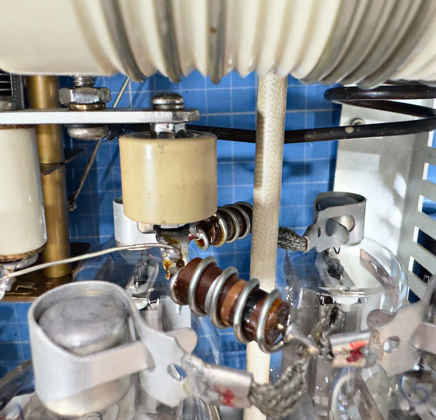
Opps that does not look nice.
I was secretly hoping that the problem was going to be down to the grid resistors, but it looks as though some damage has been applied to the right hand tube in the photo above, So it looks as though this will be a slow rebuild as I will have to order a set of balanced tubes from Penta Labs.
This is not looking as pretty as the rest of the Linear.
The Next job is to make a new set of these.
Okay so it is not the way that I wanted this to go, and as my AVO Tube Tester is still unrestored it looks as though I am going to have to sort out a set of tubes for this Linear, and Penta Labs are certainly the only good source that I know of at the moment and as they are in the USA it will take a while to get to me. In the meantime, I will give it a good clean, de-solder and test the grid resistors and possibly replace if needed. So this is it for this part of the repair and I will post a new page later when I have a suitable update.
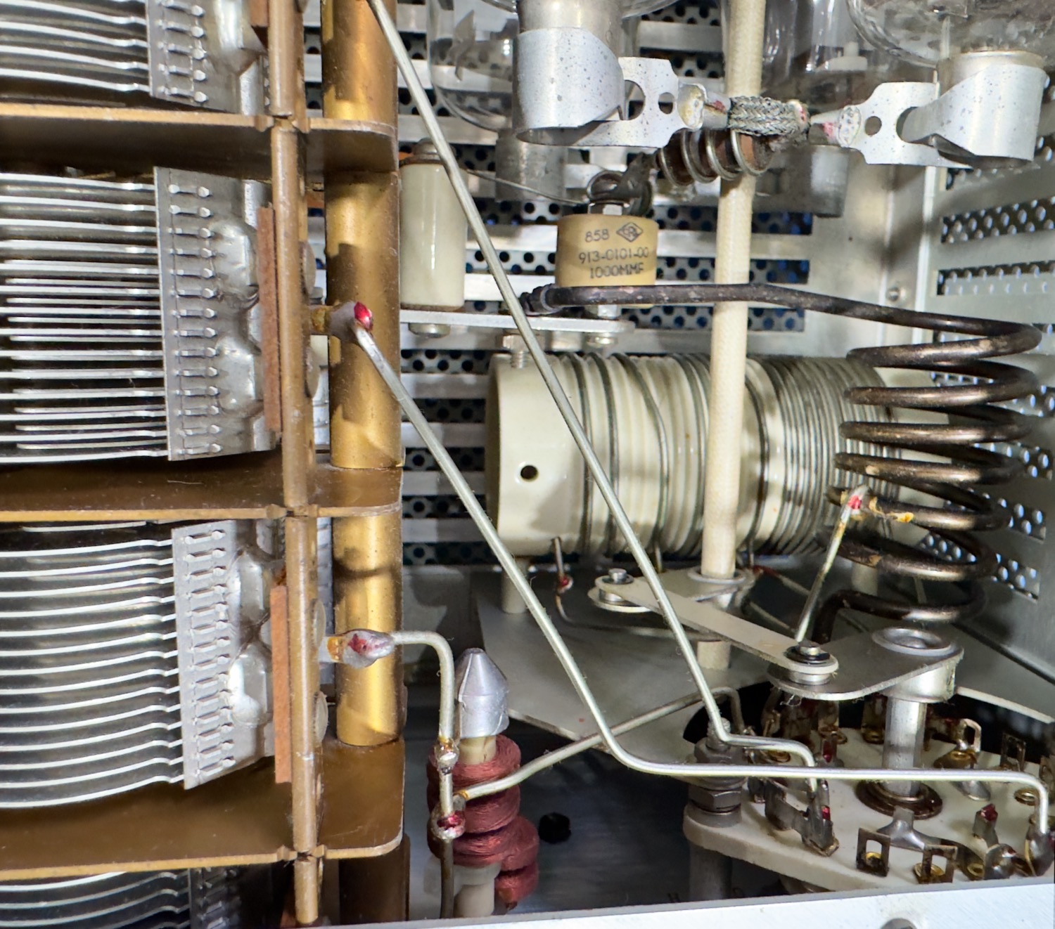
Mike N7TLL has suggested from looking at the photo’s that the age of my little linear os roughly around late 1968 to 1970.
He suggests that a good way to age these collins units is to look for date codes of the High Voltage Filter Caps but he confirms that this one has be has been modified with a updated ‘High Voltage Rectifier’ PC board which is not original but acceptable. Assuming the B+ reading are within limits.
He suggests that as one or more of the Grid Ring 47 Ohm Resistor failed the unit possibly experienced a Plate to Grid Short (PTGS).
He suggested that at least one of the 811A tube will need to be replaced, and as I have so far seen, one of the tubes does look suspect.
He also commented that hopefully that resistor failure protected the other components such as the T/R relay etc, so I will of course check this out.
He also stated that when I replace the bad tube(s) they don’t need to be a matched set, the tubes run in parallel. I would be thinking about ordering a nice new set of four new 811A tubes only because I feel this beast deserves it.
Another good hint is to check the Grid 220PF bypass Caps C22 thru C25. The last PTGS that he repaired the grid by-pass cap common to the PTGS tube had suffered a catastrophic failure along with the resistor.
Thanks Mike N7TLL for all the hints it is very much appreciated.
My Shopping List
4 x 811A Vacuum Tubes (Matched Set), finding a pristine set of tubes here in the UK is about as rare as rocking horse shit, so it looks like I am going to have to source a set from the USA and shut my eyes when they mention carrige.
2 x Parasitic Suppressor (6 Turns of 16 AWG wire and a 100Ω 2 Watt Resistor). I have a few Carbon Resistros hear but whether they are within Tollerece I am not sute, so again I may need to source a few of these from the USA as well.
I am sure that there will be more to this later on, but I will now wait till I have a good set of replacement tubes, I am hoping that I can find a set more locally than the USA, but if not it looks like it will be months before I get round to carrying on with this repair, I would say restoration but this Amp is just beautiful, anyway, if anyone would like to add ay suggestions, I would be very grateful, I have not had ANY Collins equipment and therefore I am sure that I should check out a few other things as well.
I may need to locate a source for any Carbon resistors that do not have any internal inductance, it seems that this is not good in these amplifiers.
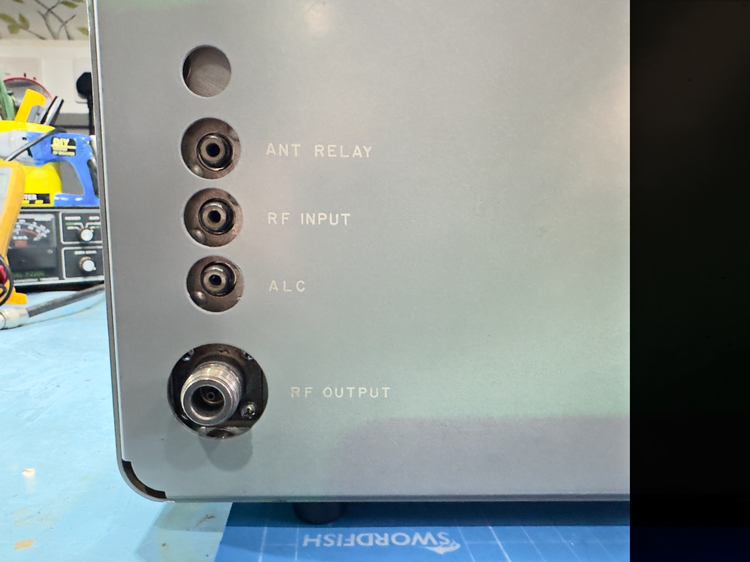
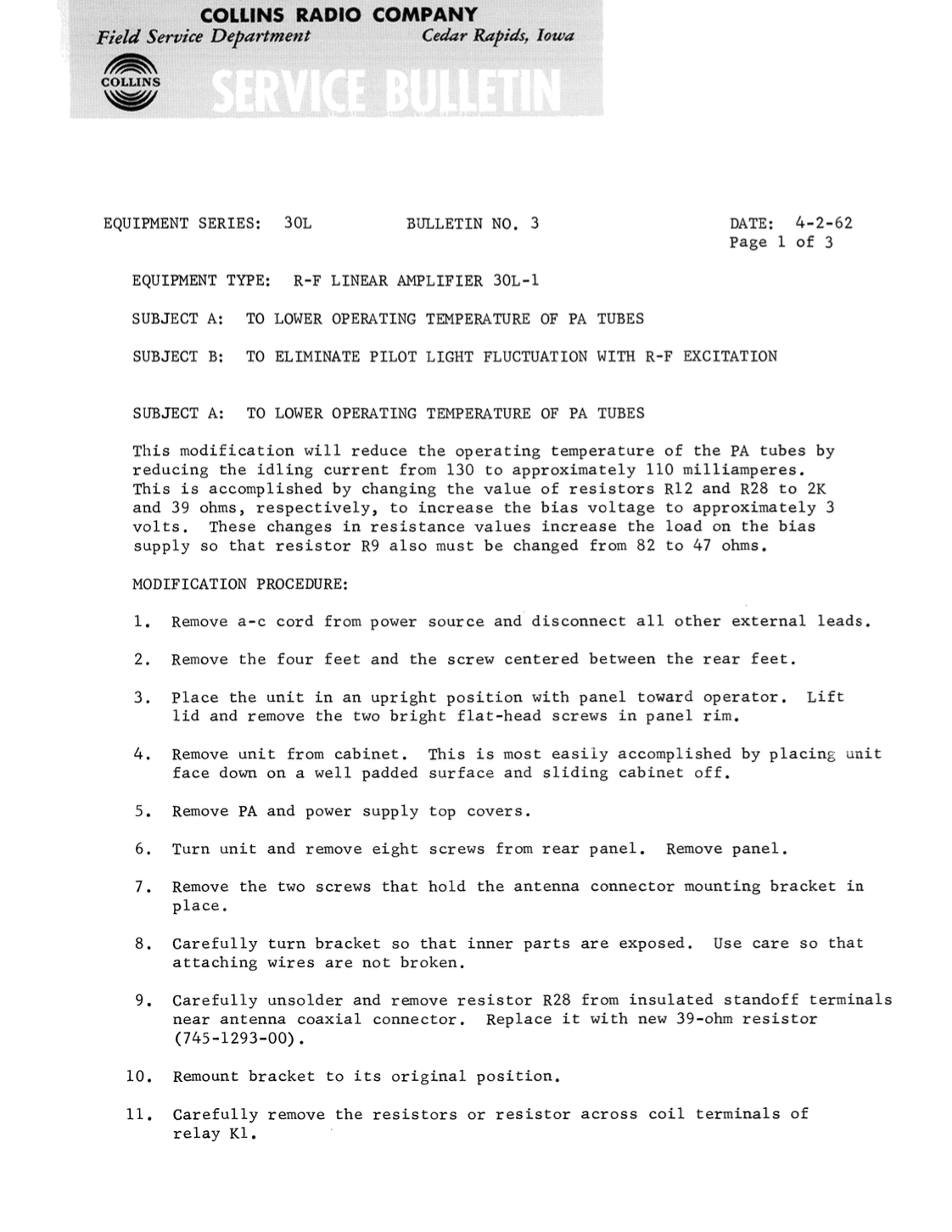
The Collins 30L-1 has unsafe wiring in the power line circuits. The wiring suggested by Collins violates wiring codes, and places unnecessary stress on the power transformer.
Collins violates two rules with their original wiring:
The black cord wire, on 120V, is the “hot” lead. The black wire must always be switched and fused. Collins originally shows the cord wired so the white (neutral) is switched and fused.
Collins grounds the 120V lines from the transformer primaries to the chassis. This is illegal, unsafe, and it can place significant stress on the transformer when on 240VAC system. It can also back-feed the house wiring system if a home breaker or house wiring connection opens, creating a shock and fire hazard.
While not perfect, the simple change in wiring below makes the amplifier much safer, and removes unnecessary stress from the transformer.
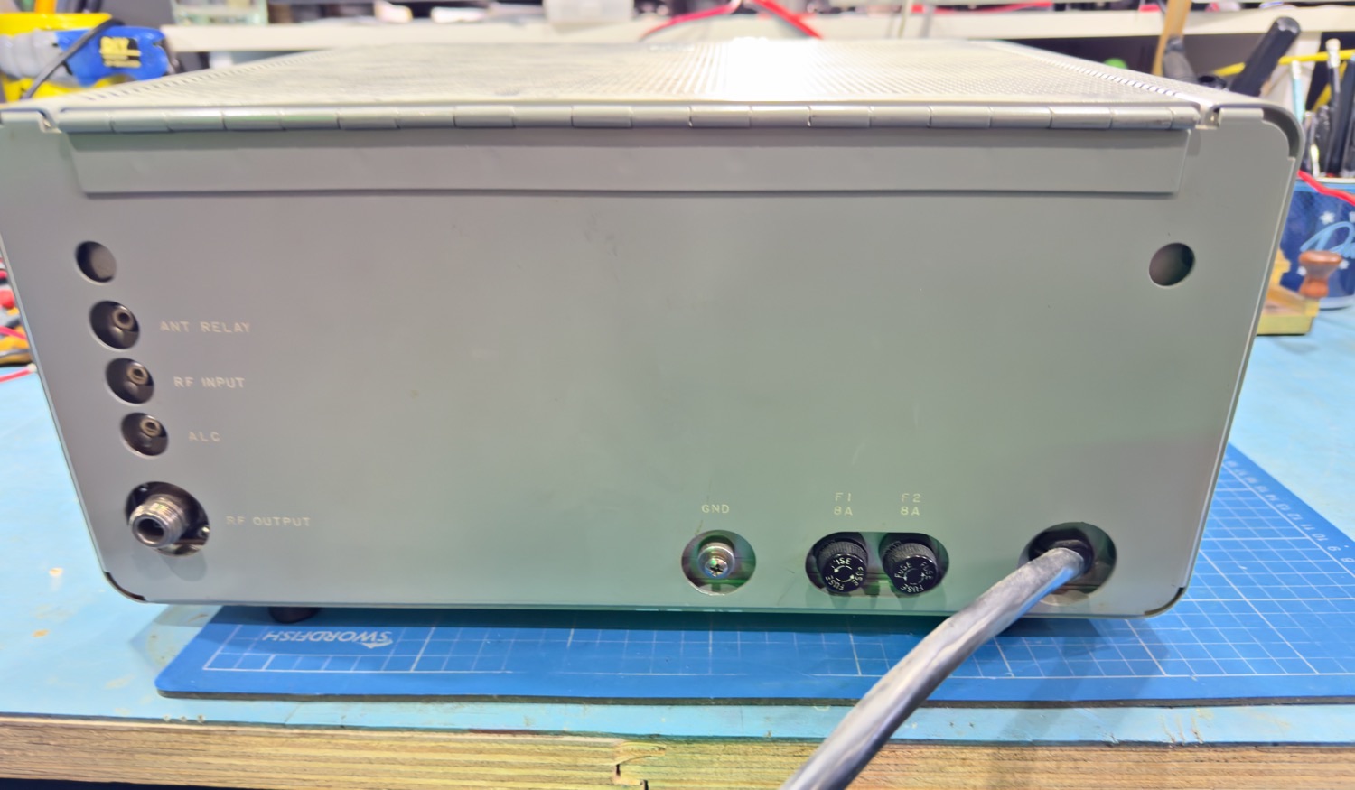
Note:
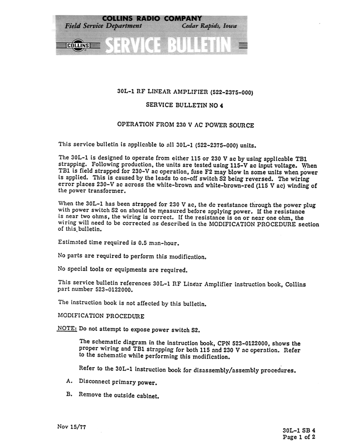
Technically, on 240 volts, both sides of the mains should be fused. Ideally, fuse holder F1 and F2 would be inserted between the power line and TB1.
The ideal solution would require rewiring the entire Collins primary system. This wiring is a compromise based on retaining as much of the original wiring as possible. Despite being less than ideal, this wiring is much safer than Collins original wiring method on TB1, for both the power transformer, the operator, and the dwelling and occupants.
The only worry with this wiring is one side of the 240v, the side to the fan and to the white/brown/red transformer lead, is not fused. This means there is no fuse to blow if the side to the fan C37, and to the white/brown/red transformer lead, shorts to chassis.
The power transformer is still protected for overloads.
If it were my amplifier, I would move the fuses to the cord side if I planned on operating it on 240 volts, but this wiring is still much safer than original Collins wiring.
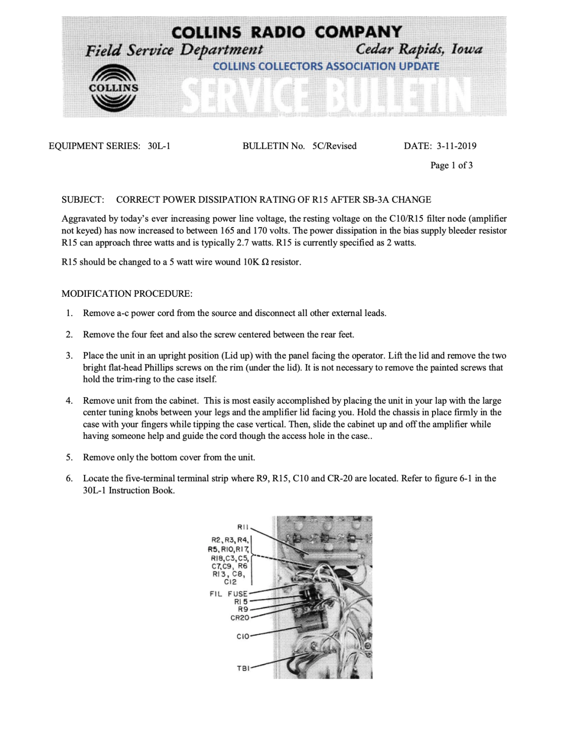
Collins 30L-1 Performance and Reliability Improvement
RF section modification of Collins 30L-1 amplifier to use 2X 572B tubes. These fully reversible modifications result in a higher duty cycle and much-improved reliability.
YouTube Video by Gerry O'Hara
Collins 30L-1 Linear Amplifier Demo
This linear amplifier design dated back to the early-1960's. It uses four 811A (or 572B) tubes for up to 1KW input power for 70W drive.
YouTube Video by George Blake W6BDD
Collins 30L-1 Upgrade / Rebuild Part 1
I am starting the teardown and rebuild of (2) Collins 30L-1 Linear Amplifiers with (4) 811A Triode tubes.
YouTube Video by CT1JRZ
Collins 30L-1 The Rebirth
Foreign Language by Auto Translate does wonders, still well worth watching.
YouTube Video by Amp Repair Guy
Collins 30l1 Harbach Filter Cap Board And Other Repairs
Here I show another Collins 30l1 in for repair.
YouTube Video by Kevin Drury
Putting New Filter and Diode Board. Collins 30L-1 Amplifier
A Man of Little word working on his 30L-1 in the Sun.
YouTube Video by Amp Repair Guy
Collins 30l1 Repair And Modification With Harbach Filter Board Kit
Here I show the repair and modification of a Collins 30l1 linear amplifier. Also Received a fresh matched quad of Penta 572b tubes Correction... knob insert is brushed aluminum not chrome.
YouTube Video by Amp Repair Guy
Collins 30L-1 Repair
Here I show the repair of a Collins 30L-1, Correction I called the R28 resistor in series with the key line a 47 ohm when in fact it is a 39 ohm.
I am now retired and living on the Isle of Man, my background is as varied as it gets, ranging from Information Technology to Graphic Designer and 3D VFX Artist, using and teaching Autodesk Maya, Softimage, and Smoke, one of more enjoyable positions. Since Moving to the Isle of Man I try to keep myself to myself and work on the house, I don't do much with regards to Amateur Radio or Electronics anymore, but I am still interested in the hobby and may well get back into it one day....