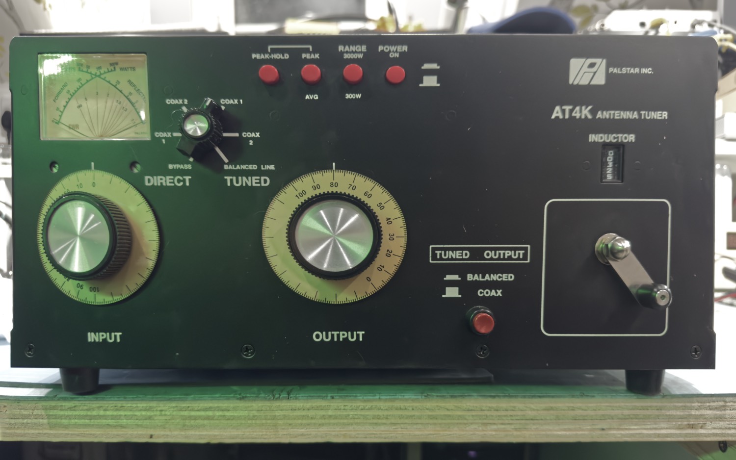
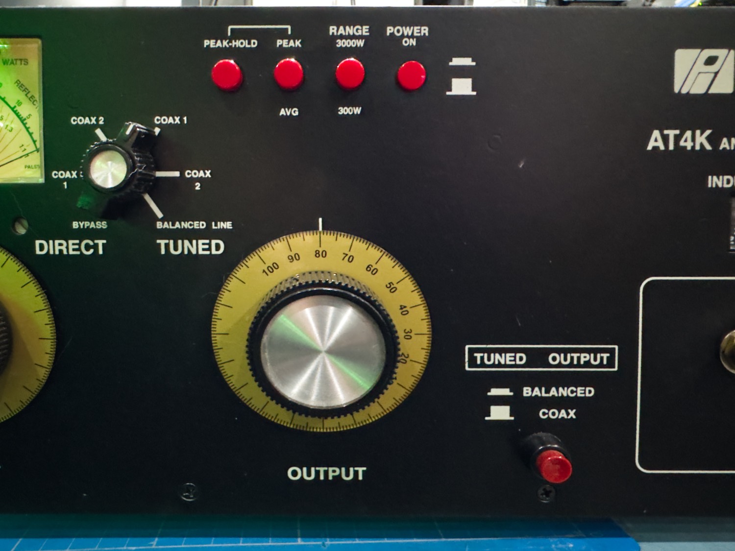
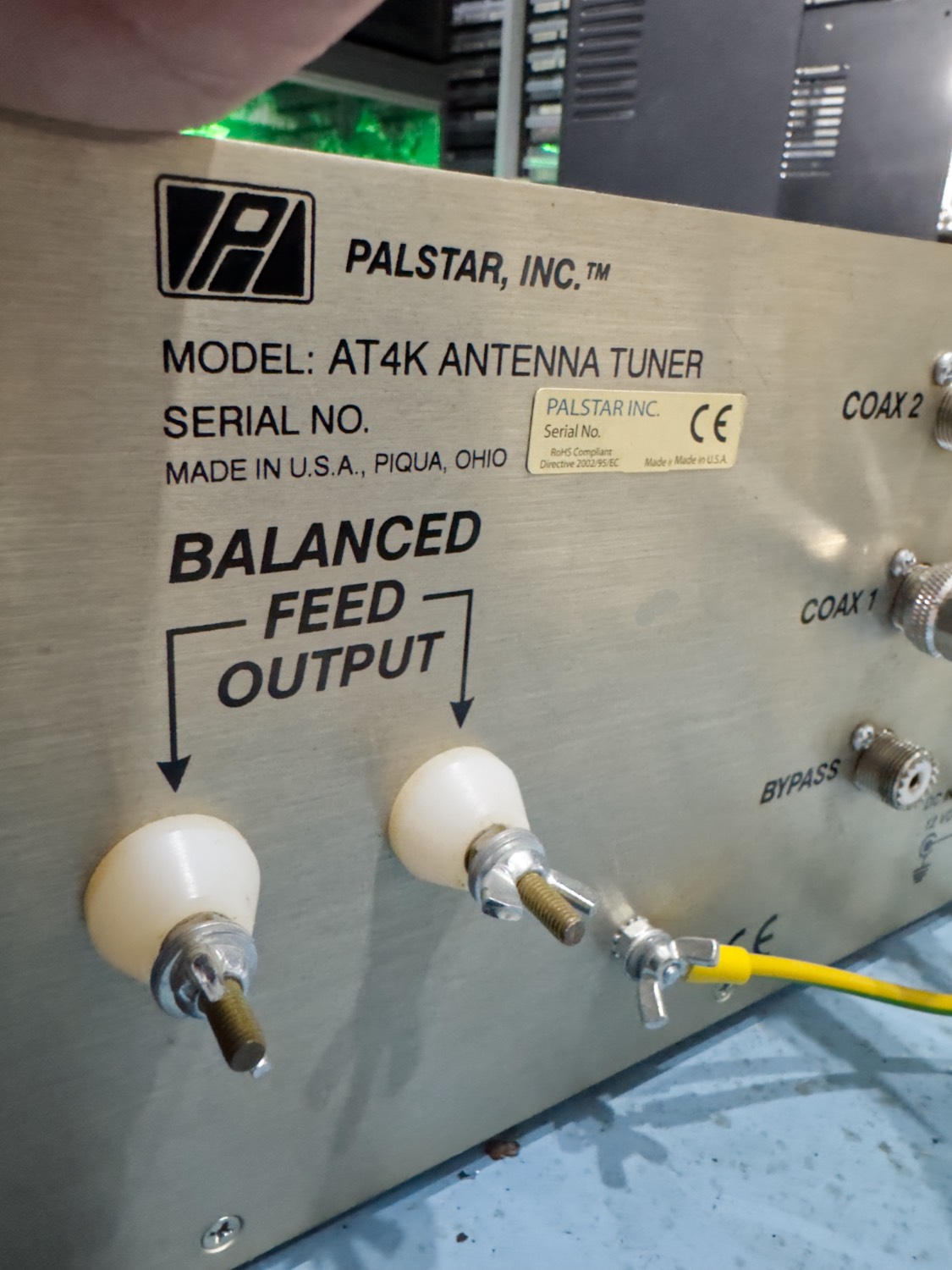
I have a problem with my AT4K, It was put on a shelf ages ago but I had forgotten why I was no using it, especially as most of the other tuners that I have here was of a lesser build quality than the Palstar Tuners, but as this is the only Palstar tuner that I have here at present, I have may other such as MFJ, Icom and Yaesu tuners, but this is a monster compared to all of them.
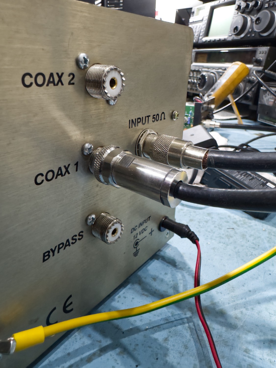
Sometime ago I managed to pull this off a shelf, dust off the top and connected it all up to see what it would run like with my Hari 160m Windom antenna with the Yaesu FTDX-10 and the option with one of the finish Linear AMP UK RF Power Amplifiers.
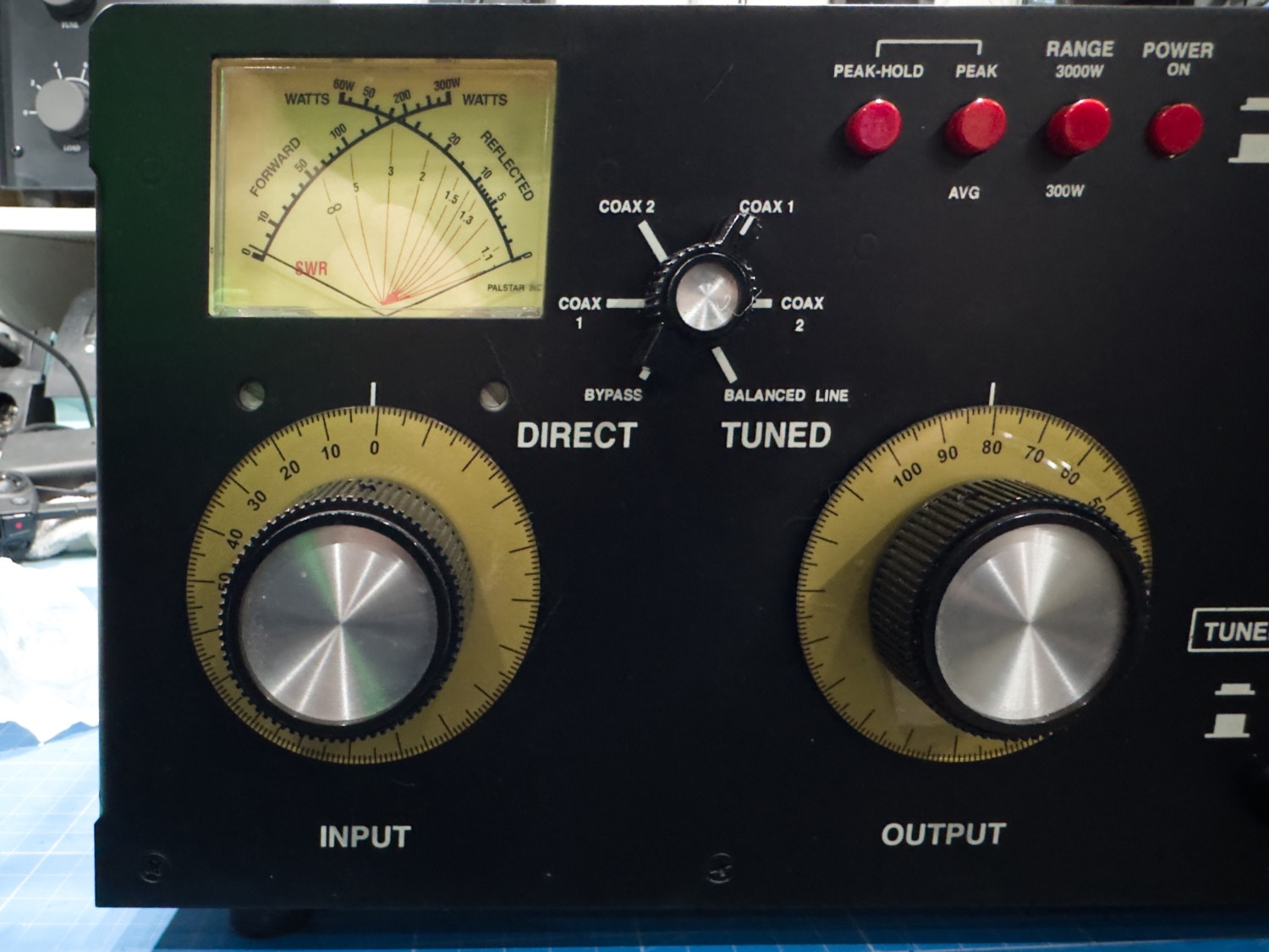
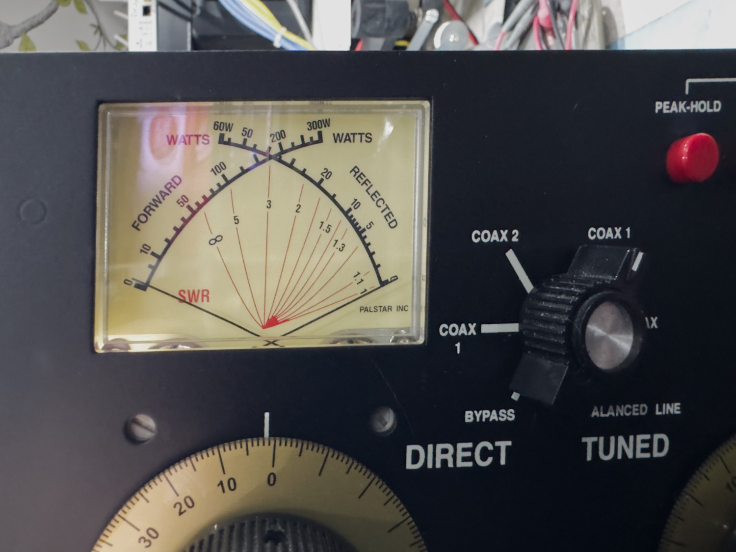
This displayed the problem that I was having with this tuner, first off turning the Inductor handle was very easy and I could easily spin the Inductor control which seemed as though there was no friction there at all, and trying to find the sweet spot was a real headache, and just trying to rotate the control just a small amount you would see the needle display a movement on the needles but then when you stopped it would vanish and trying to tune in using the INPUT and OUTPUT knobs was just not right, in fact it turned out to be near impossible to tune in an antenna that is basically pretty flat SWR across most of the bands.
So, I removed the cover to see if I could see why this tuner was basically acting useless.
Looking over the Inside to see if there was a broken or loose connection, or something that would explain this problem. One of the first things that become apparent is the build quality, I know that there are a lot of tuners that I have not yet seen, but looking at this alongside the Many MFJ, and Older Yaesu Tuners from the FT-101 and 902 era, you cannot compare them really, the Palstar build quality is just ‘outstanding’ ad you can see that it has been built for 4000W + and not what looks like it could not even handle 100W.
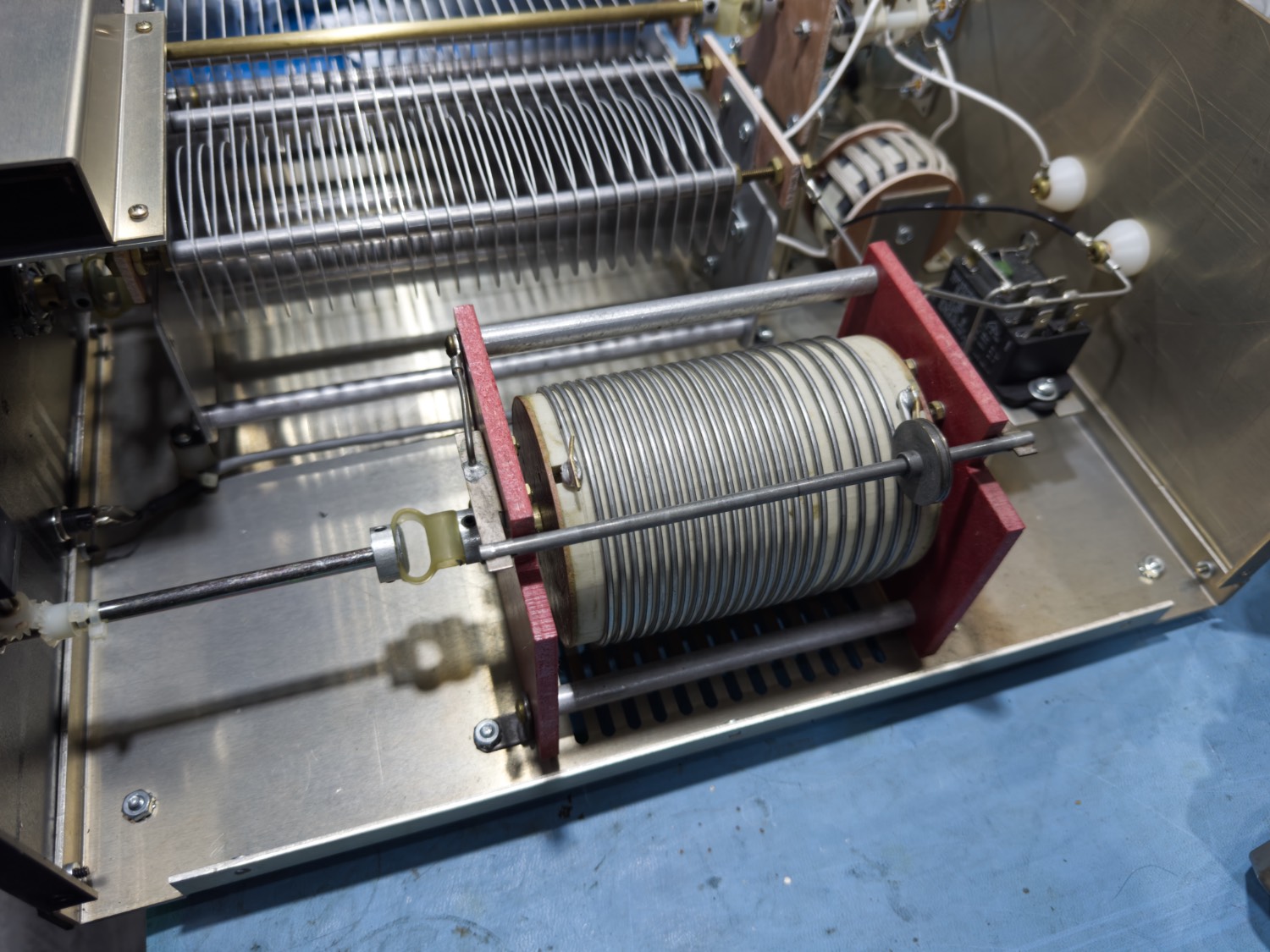
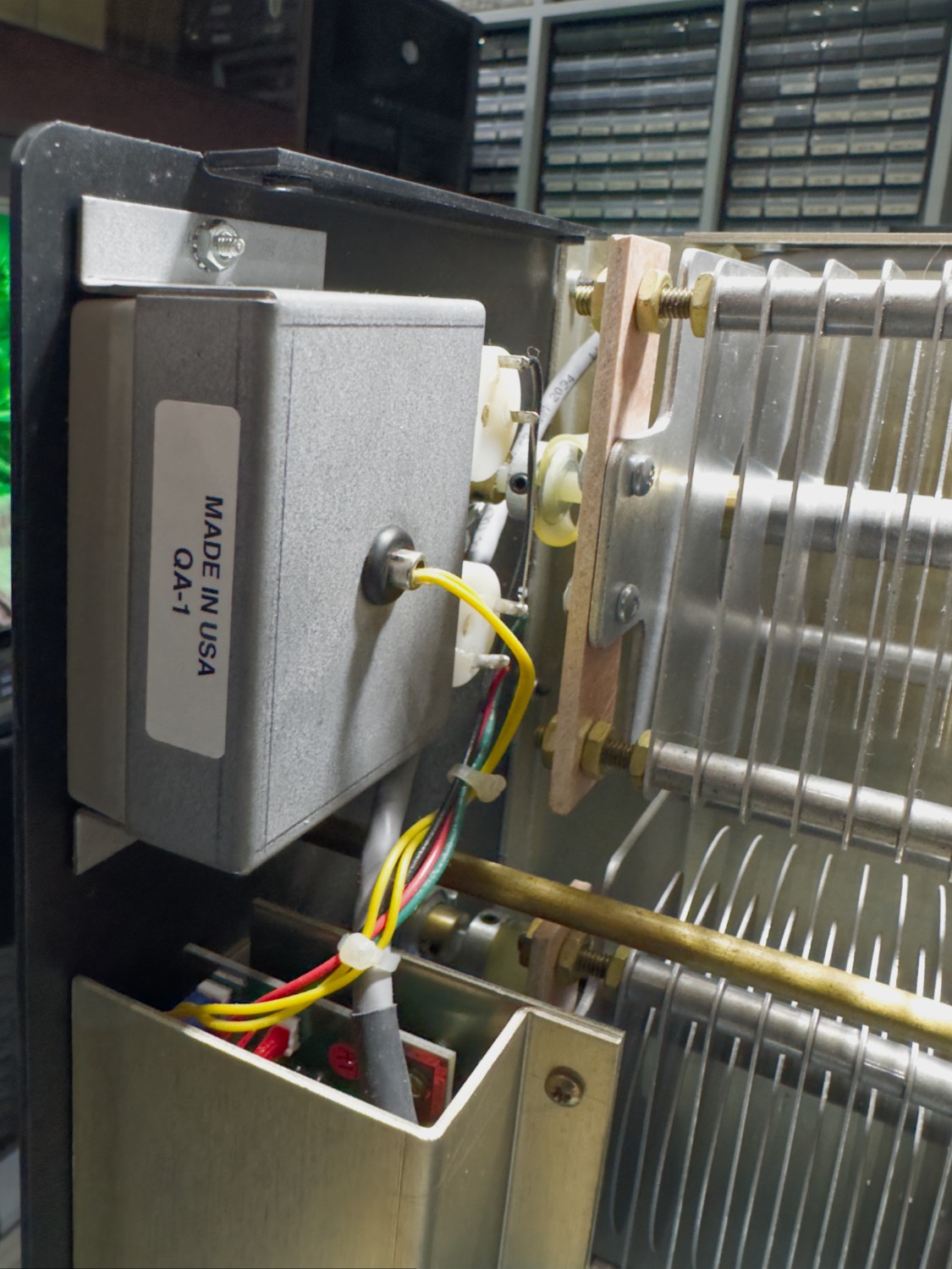
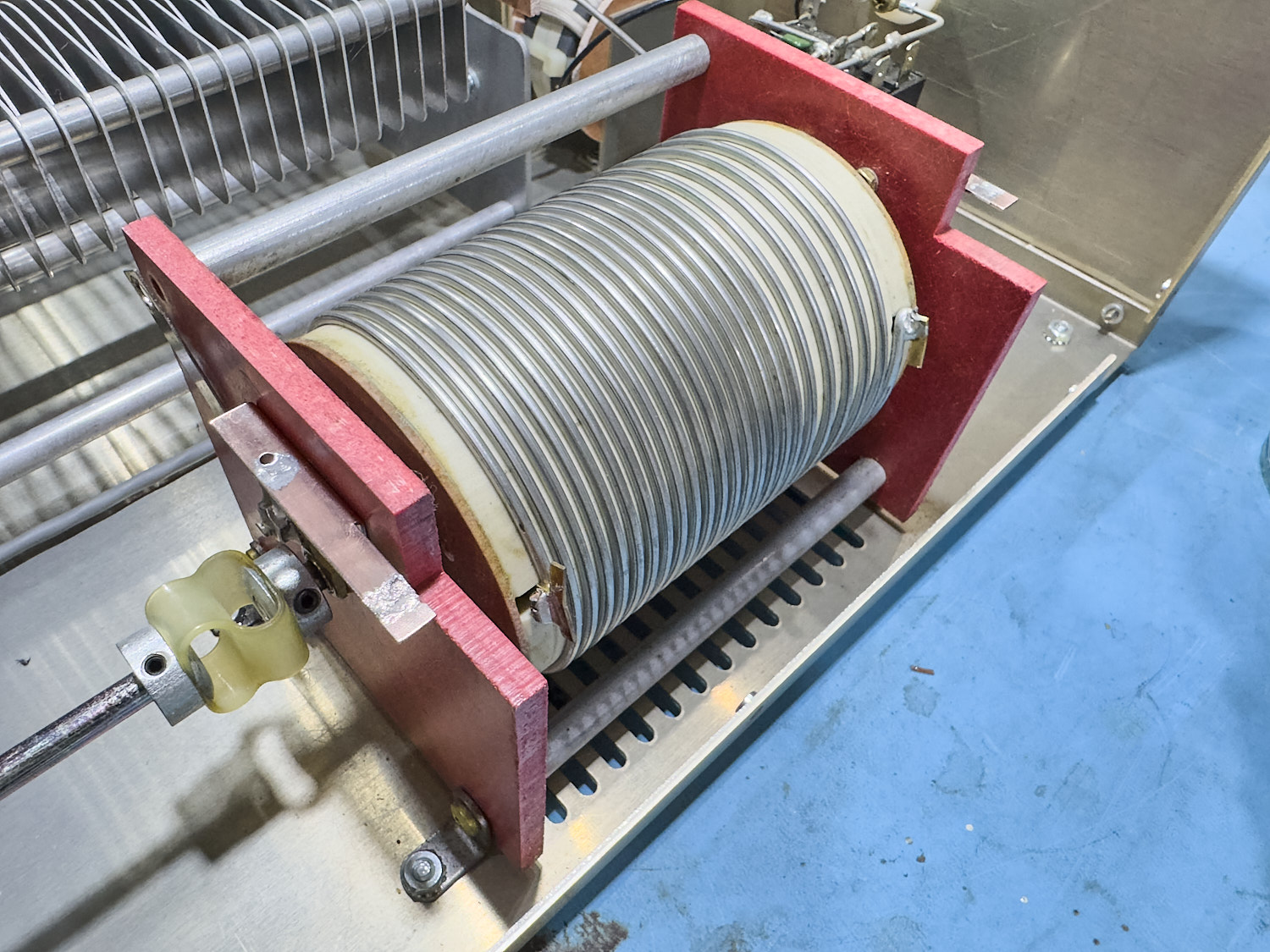
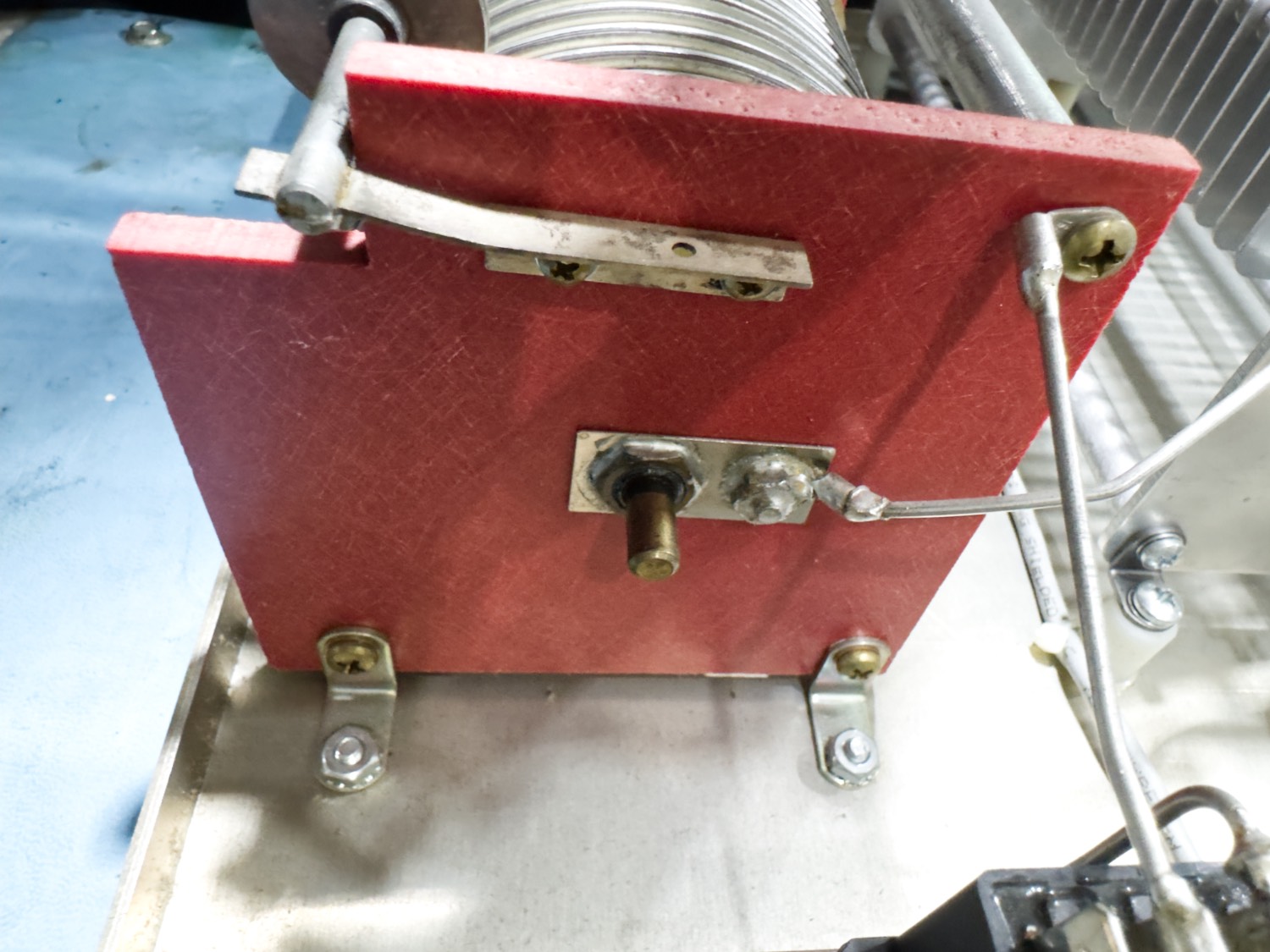
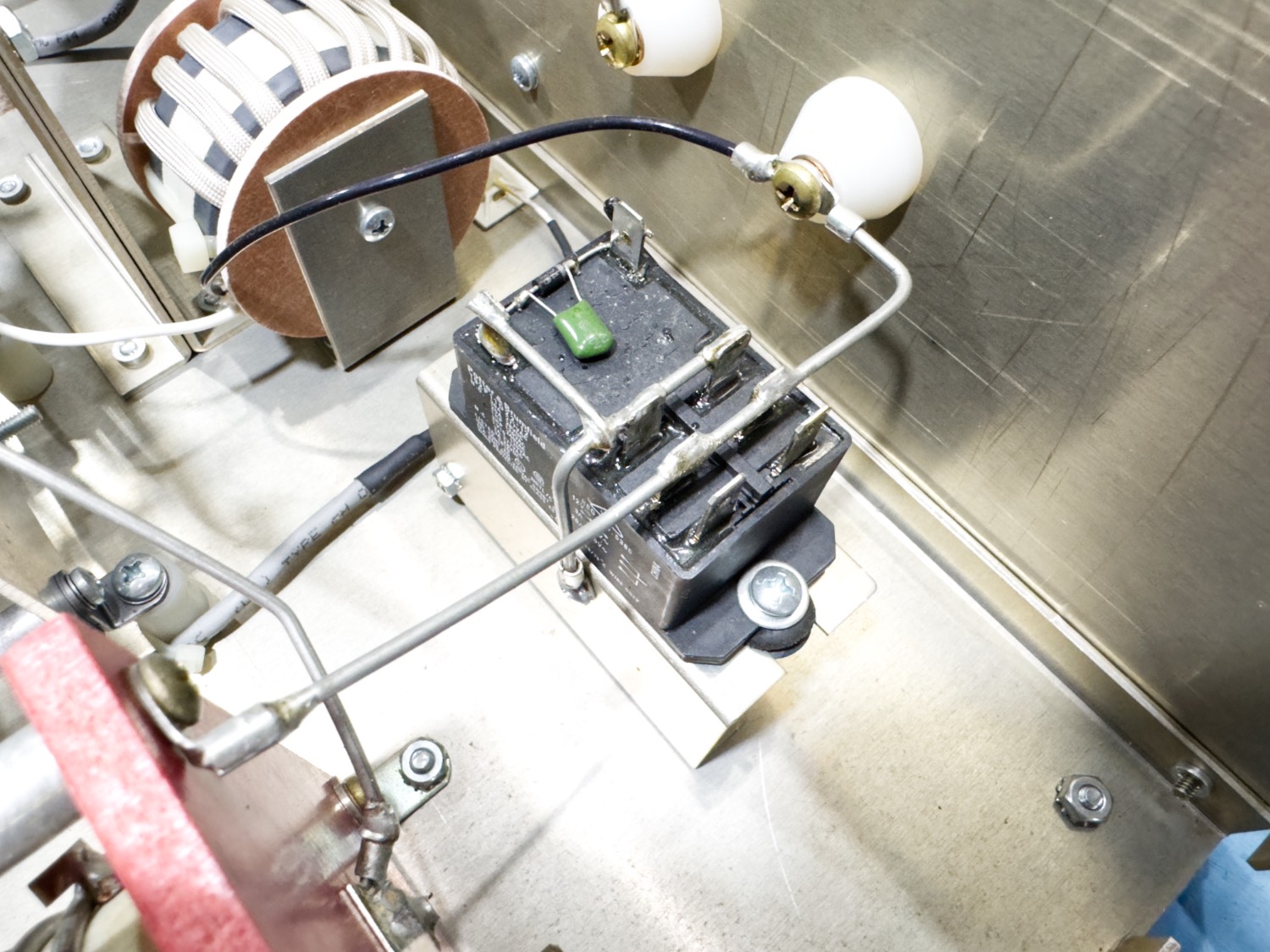
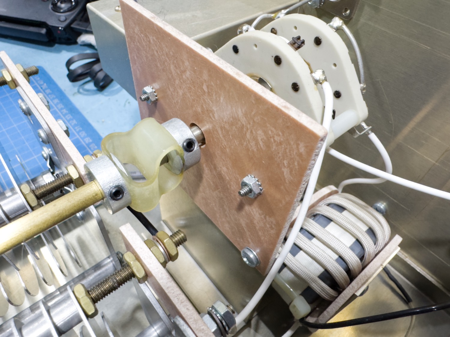
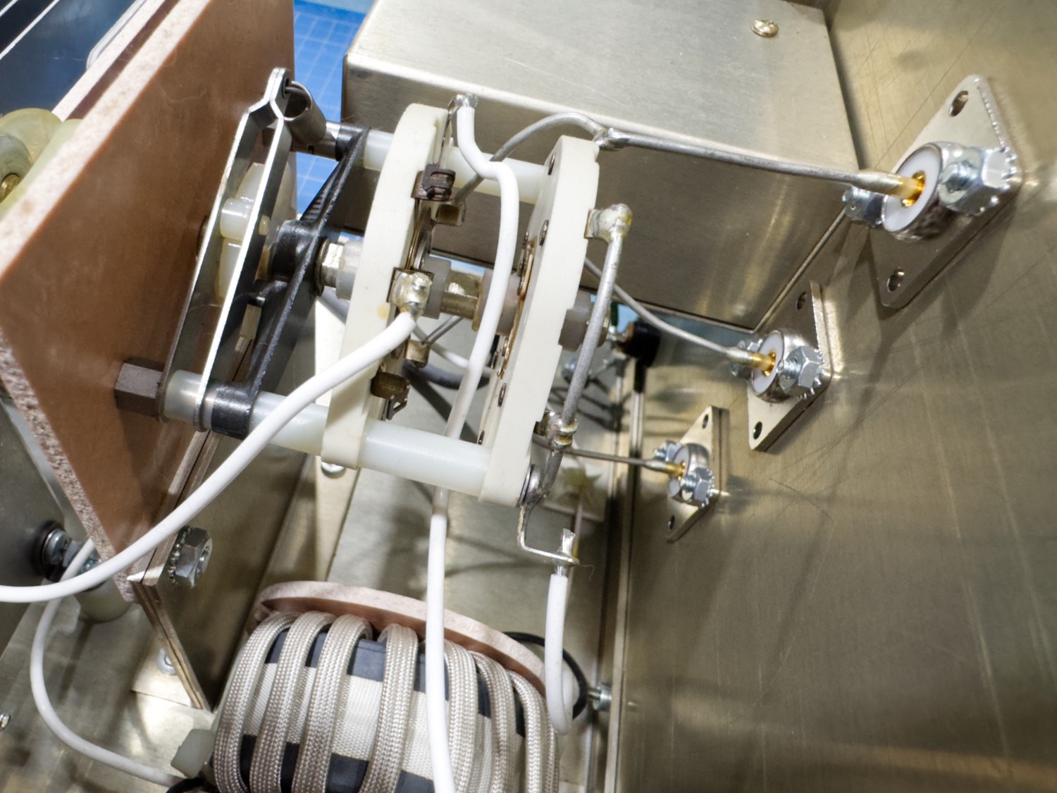
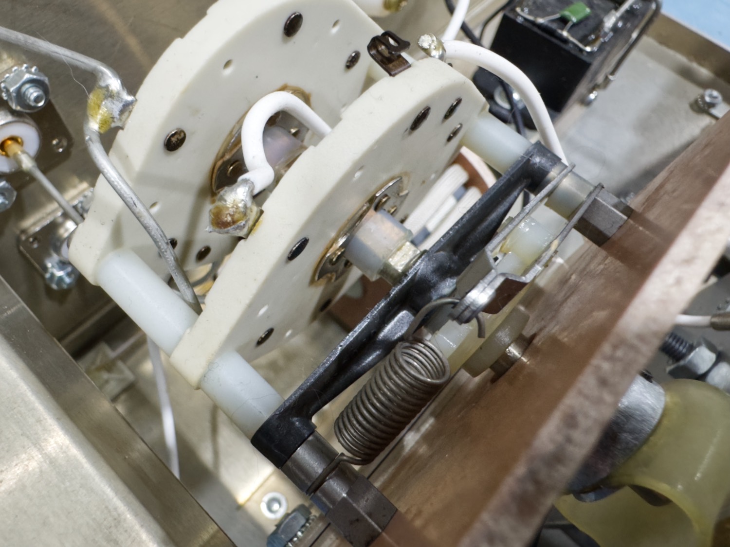
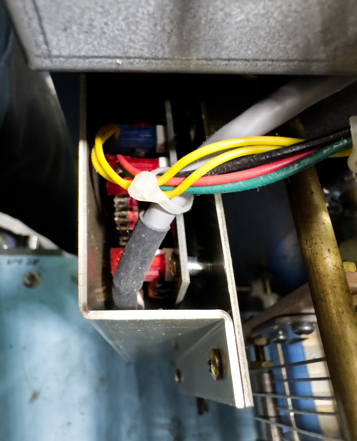
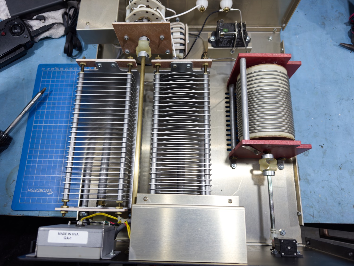
First Look at the Internals of the Palstar AT4K
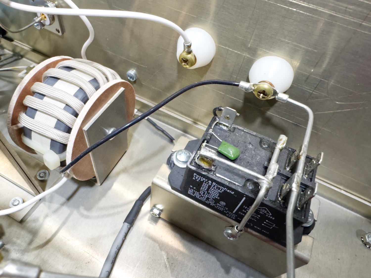
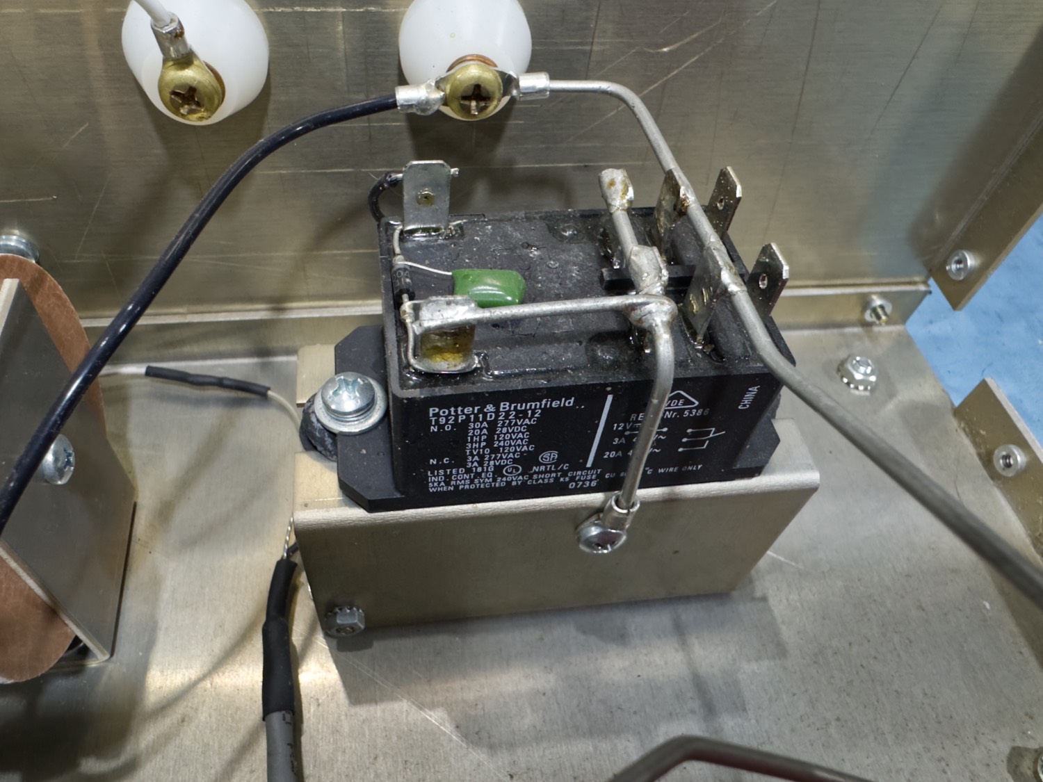
Certainly Built to Handle Power, The Later Models have the Much Bigger Relay.
Where ever you look, nothing has been skipped!
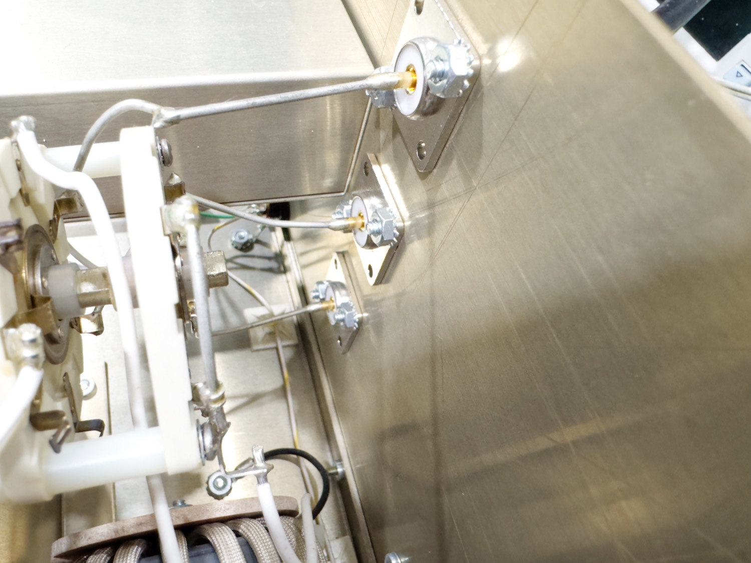
Substansial Metal is used all over the inside of the tuner for Sheilding.
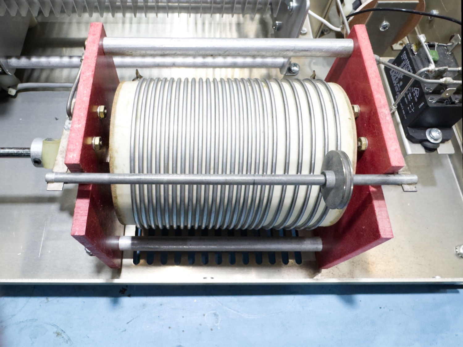
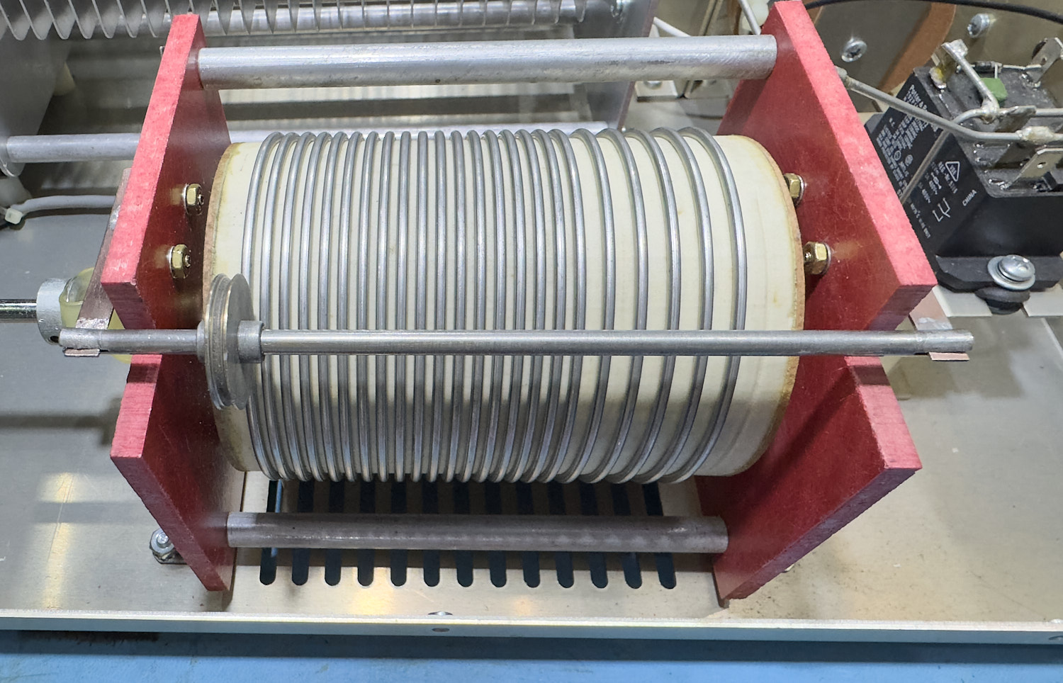
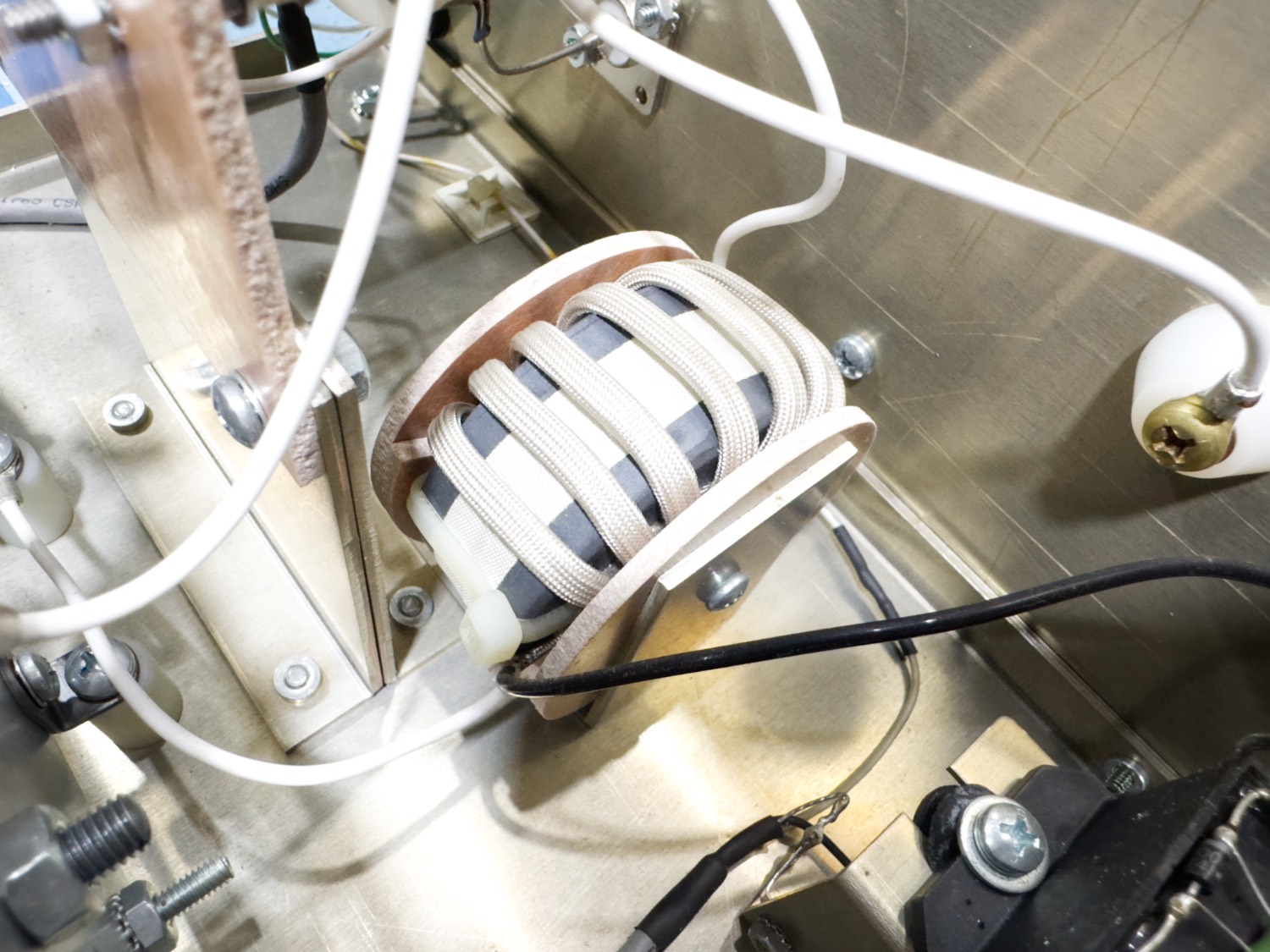
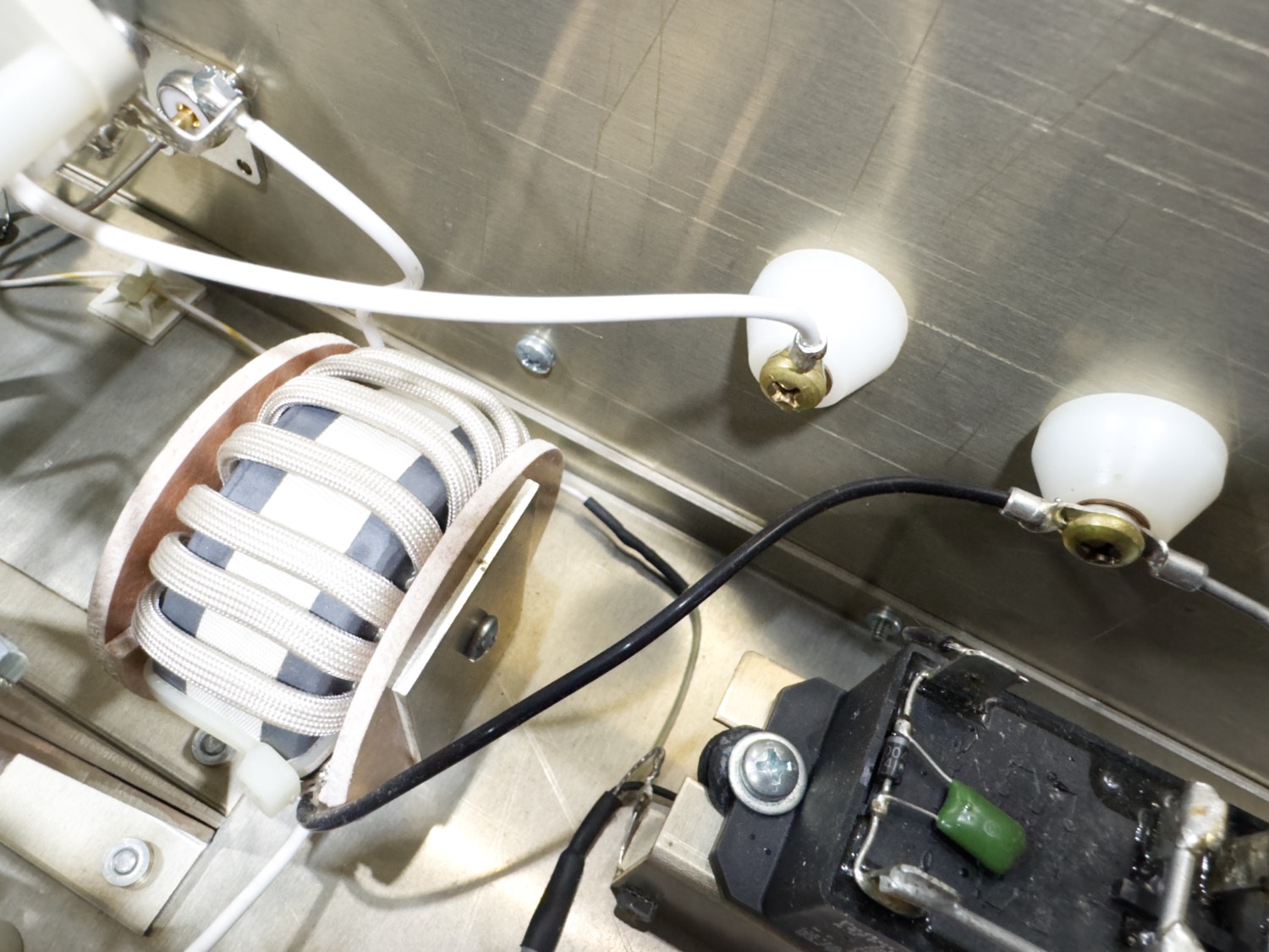
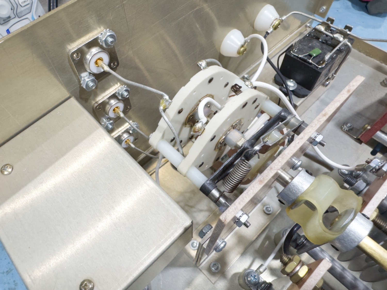
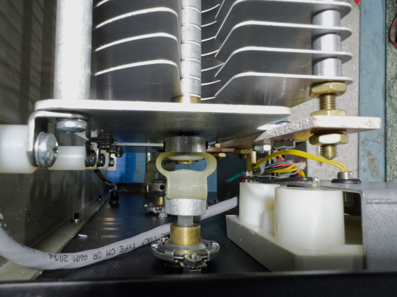
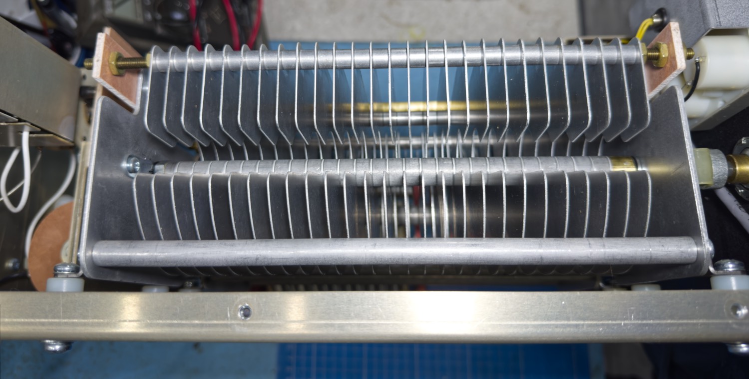
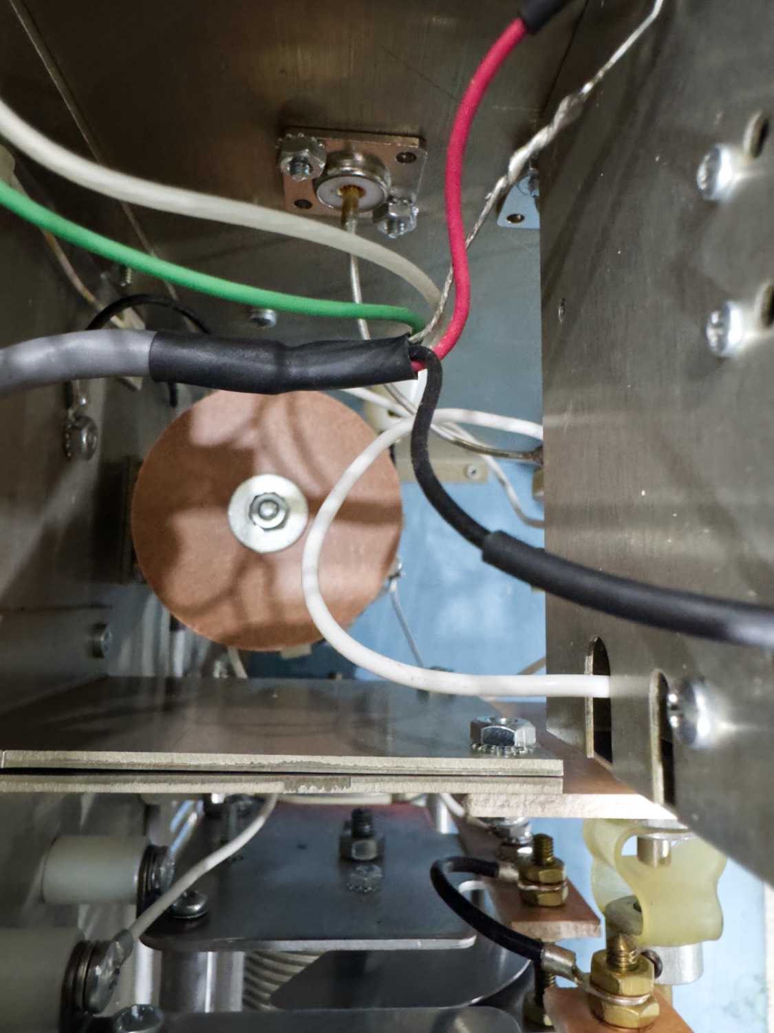
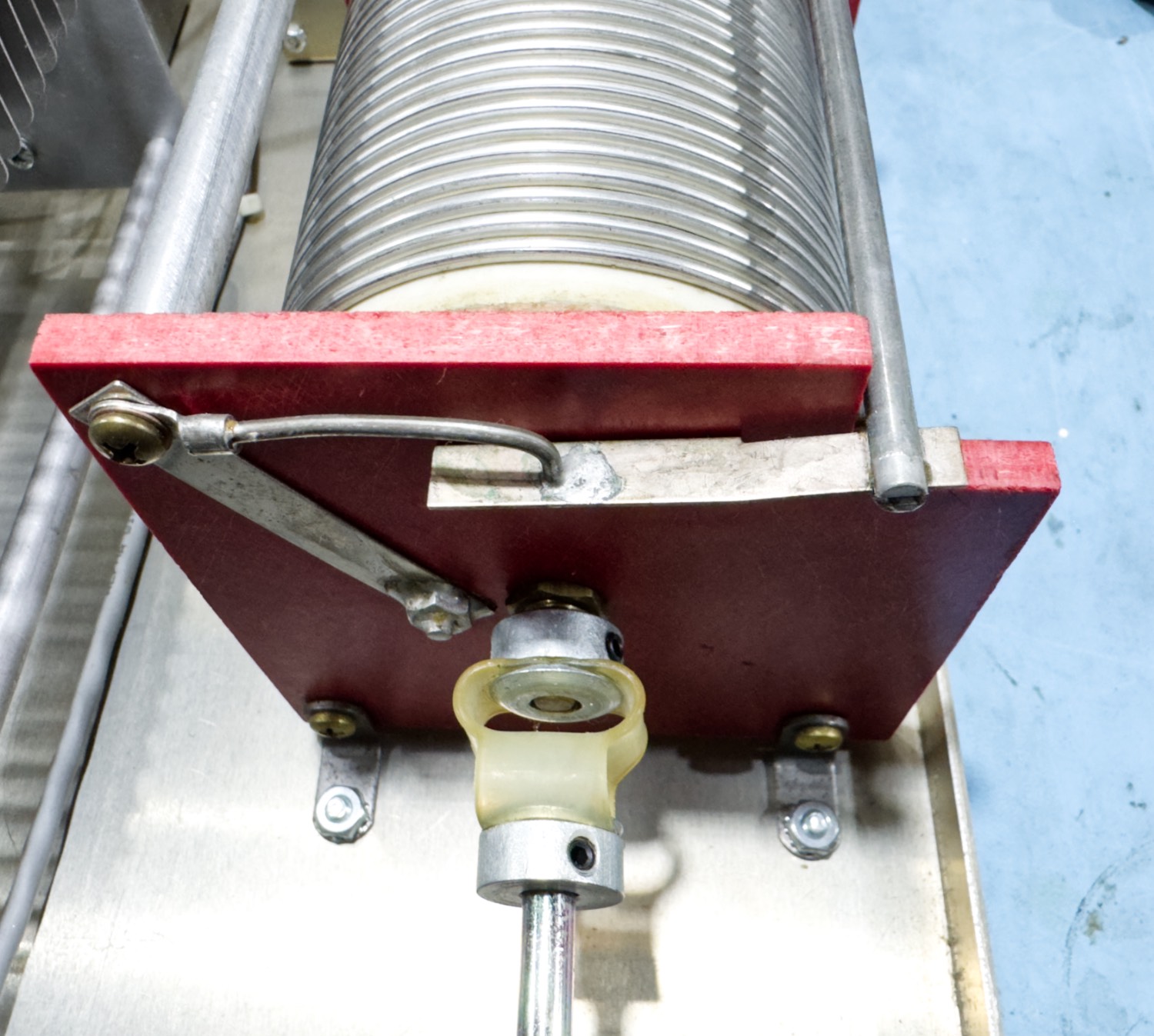
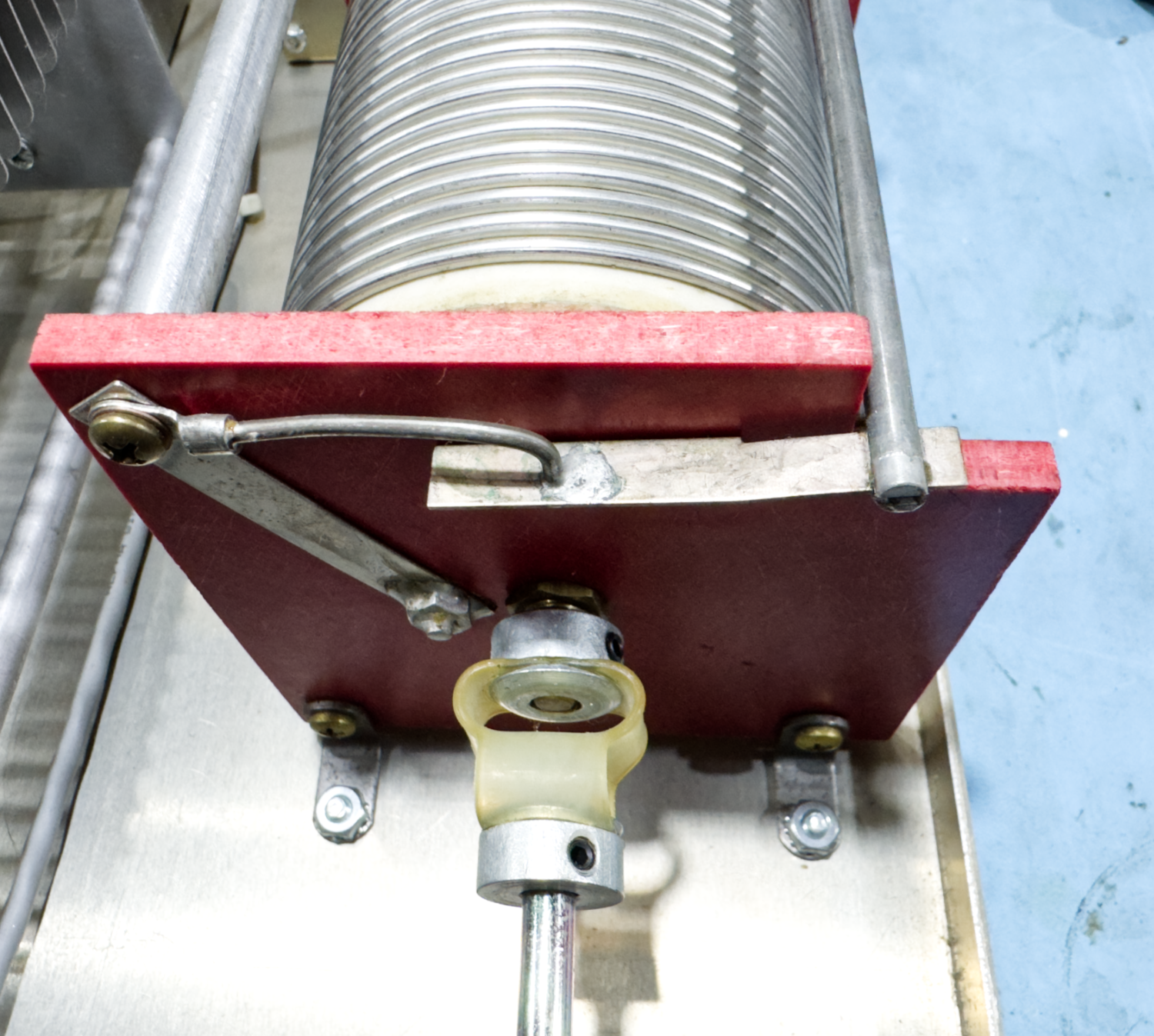
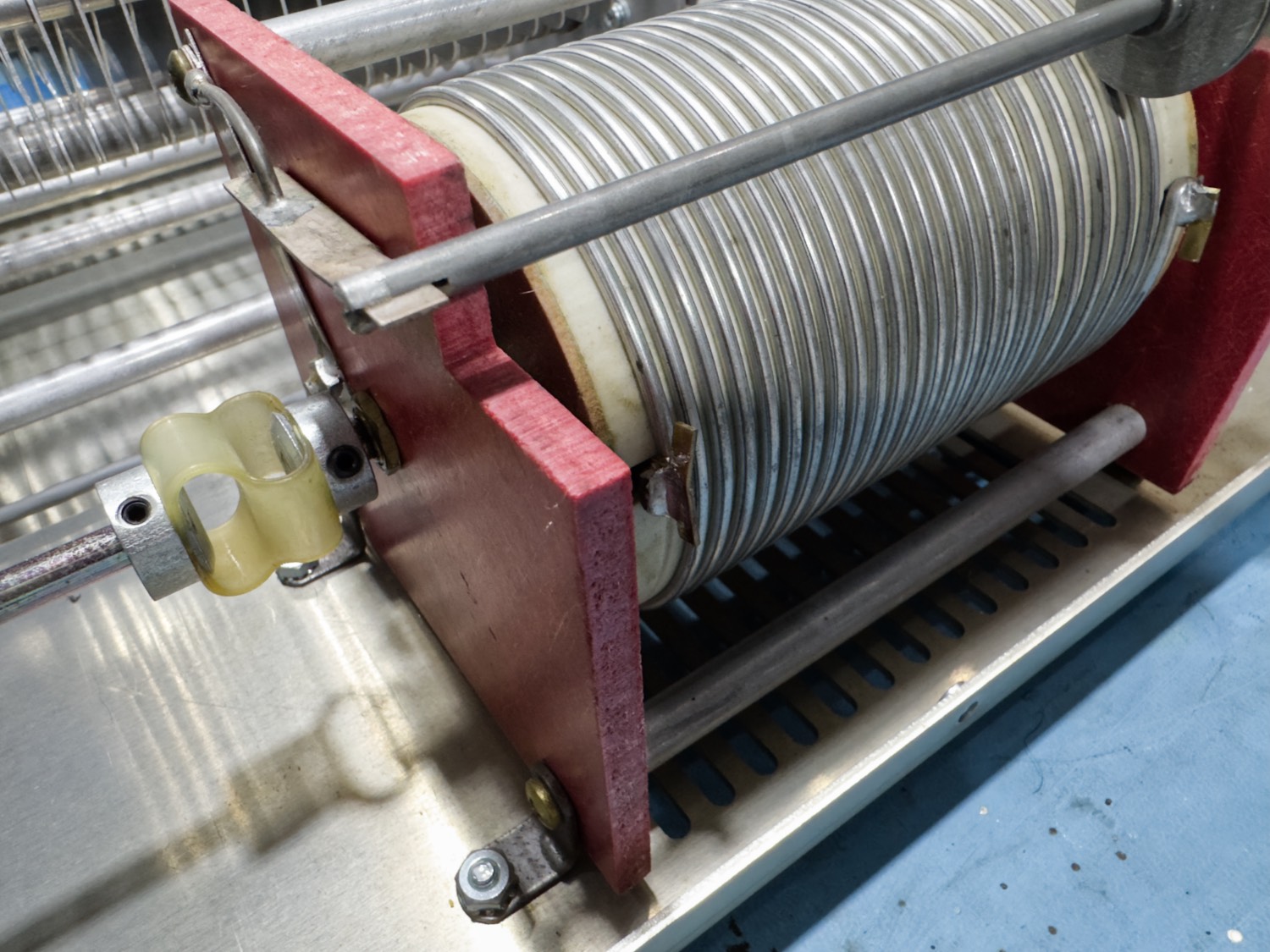
So happy with the build quality all over the unit and started to look at the one item that was causing me a problem, The Tuning Inductor.
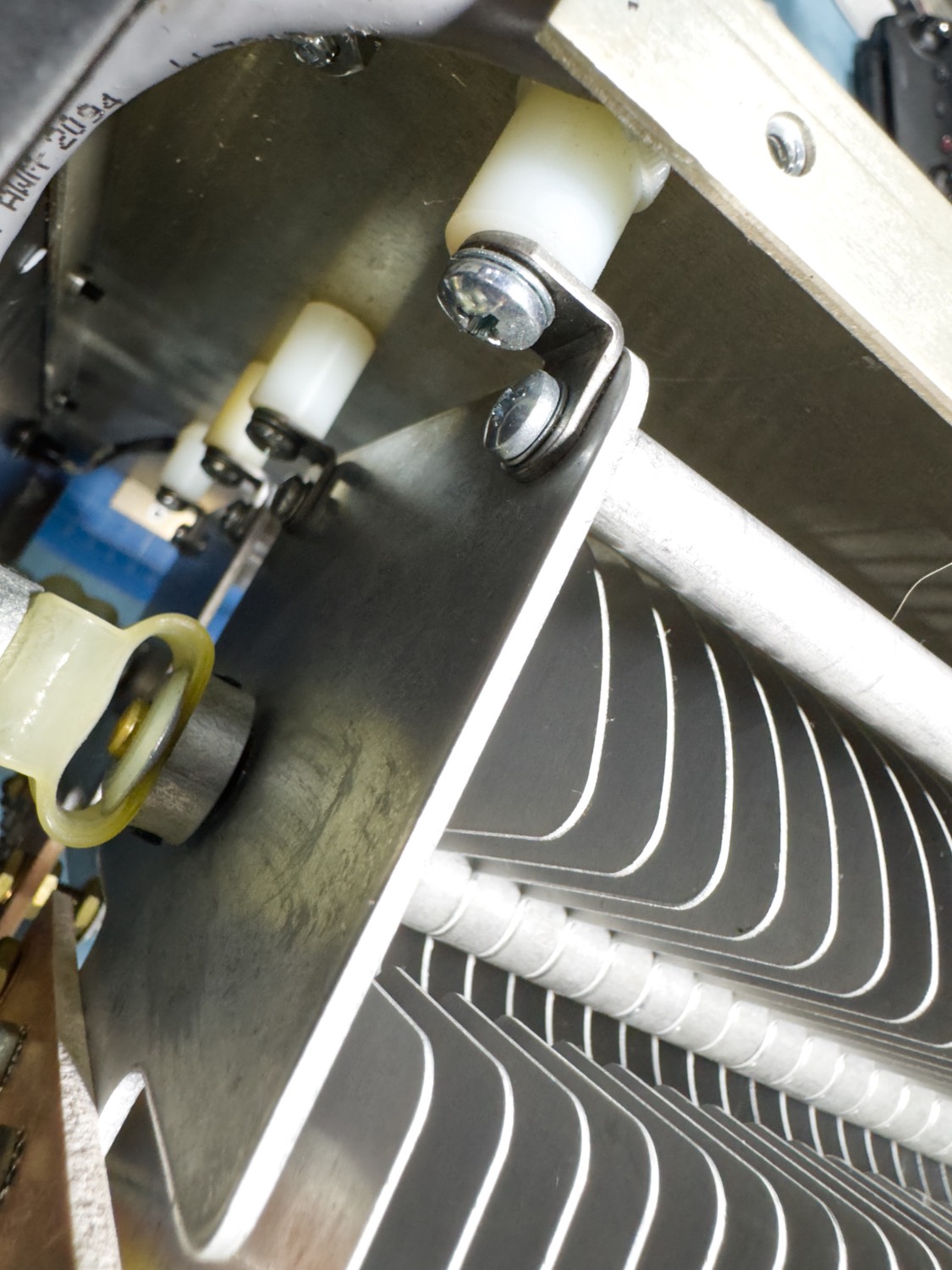
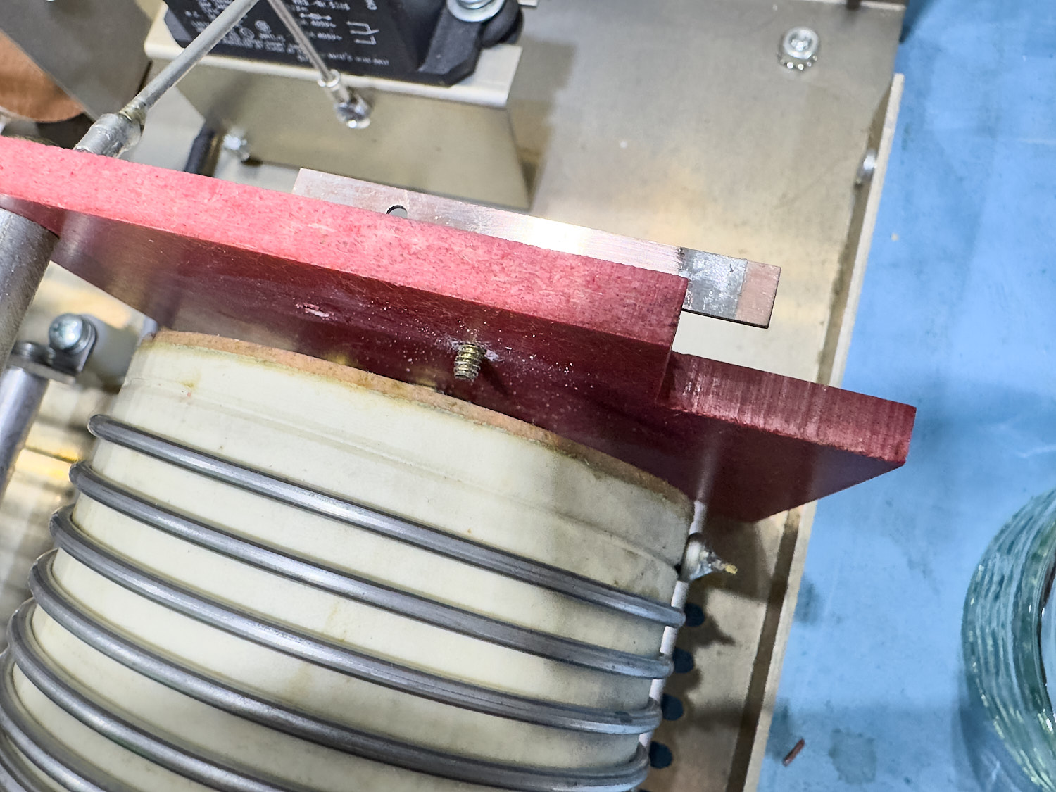
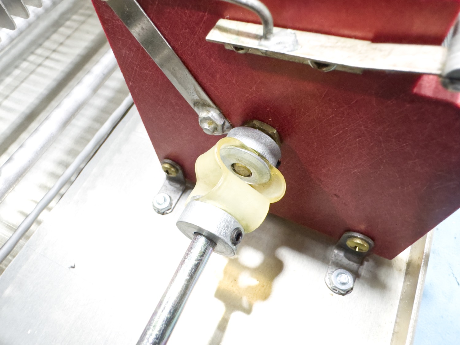
This was what was causing my problem - The Tuning Inductor!
The Build quality was not entirely the problem.
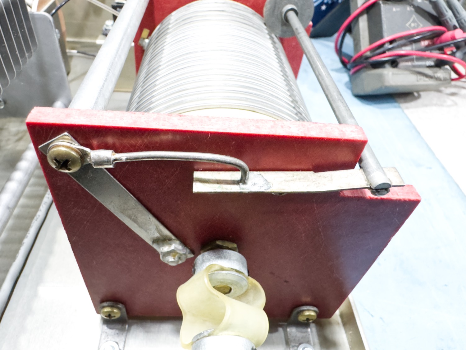
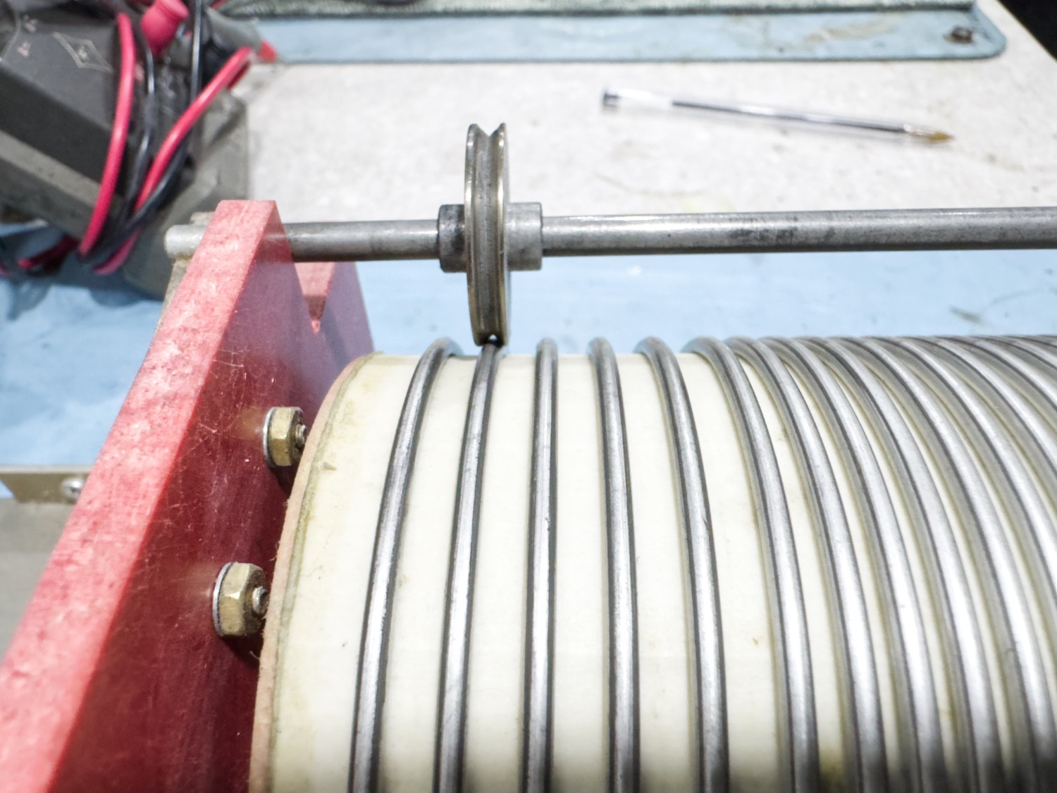
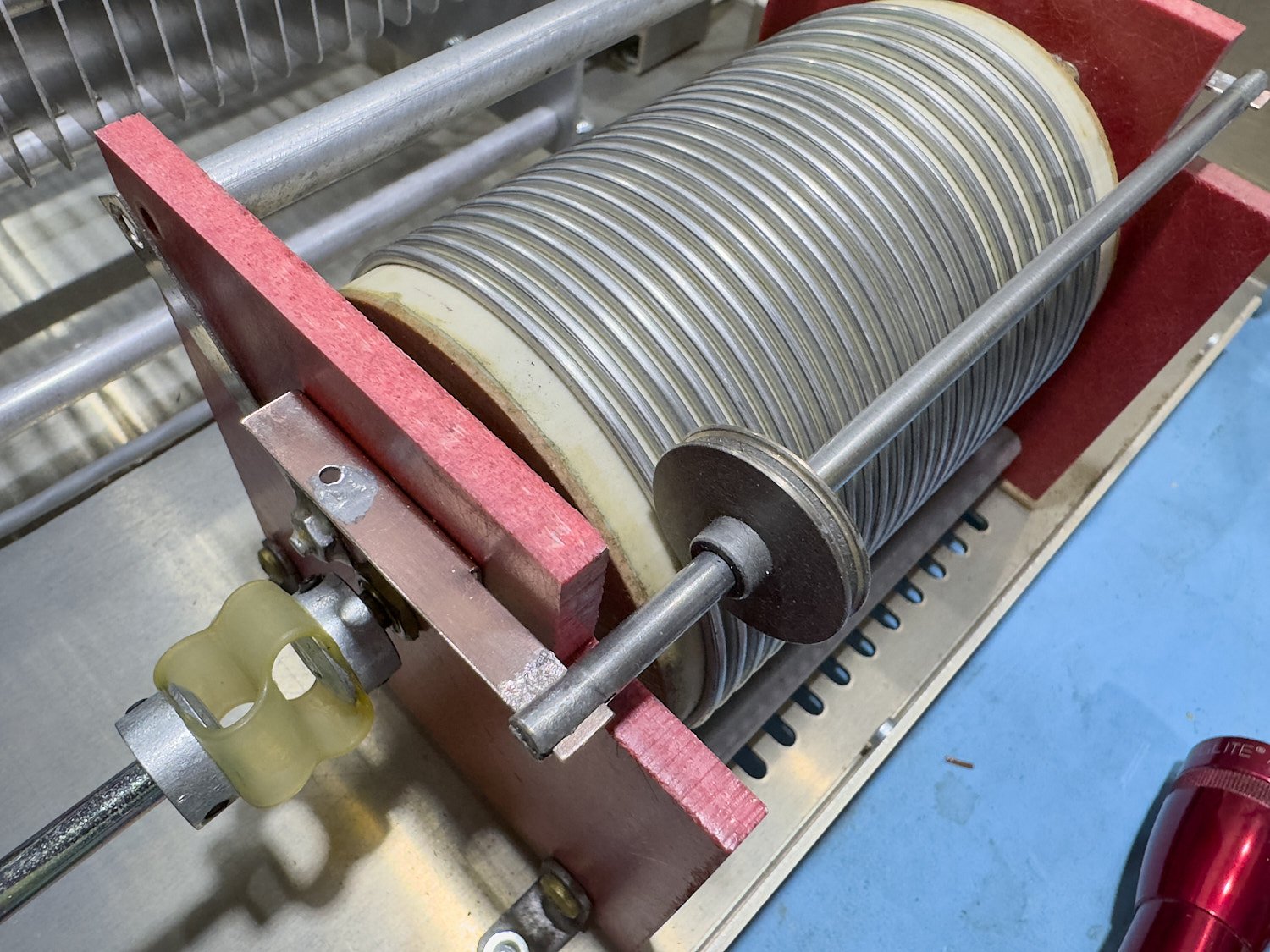
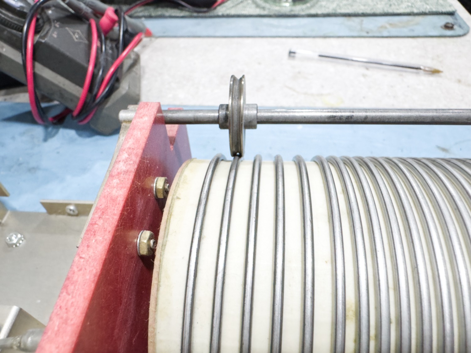
The Roller is only just touching the coil.
What I noticed is that when you turned the inductor control on the front of the tuner, the wheel would go from one end to the other end and the gap between the wheel and the coil would go from being just about okay to a point where there was basically a large gap and you could actually get hold of the wheel and move it between the coils on the drum along the bar. So, problem found…
It was at this point that I contacted a good friend here on the island to see what suggestions he had for this. He suggested that I could apply pressure to the ends to try and bend them inwards. I thought about this and to me this would kind of the wrong choice as it would or could bend the bar and deforming the bar to me is going against the build of this tuner.
At this point I tried to contact Palstar but it seems that they have moved their support to group.io/AT4K which is kind of a good thing, but I am afraid that it seems to be not that well implemented,
I set up 2 new topics 1 week apart but it looks as though it is not being managed, the only topic on there is from 2020 and it looks as though they do not want anyone contacting them as I also sent in a couple of e-mails, that also were not answered which came as a surprise as in the past Palstar were very good at answering their e-mails, has something changed?
As I have not got any suggestions regarding fixing this issue that I have I thought I would attempt to sort this out myself.
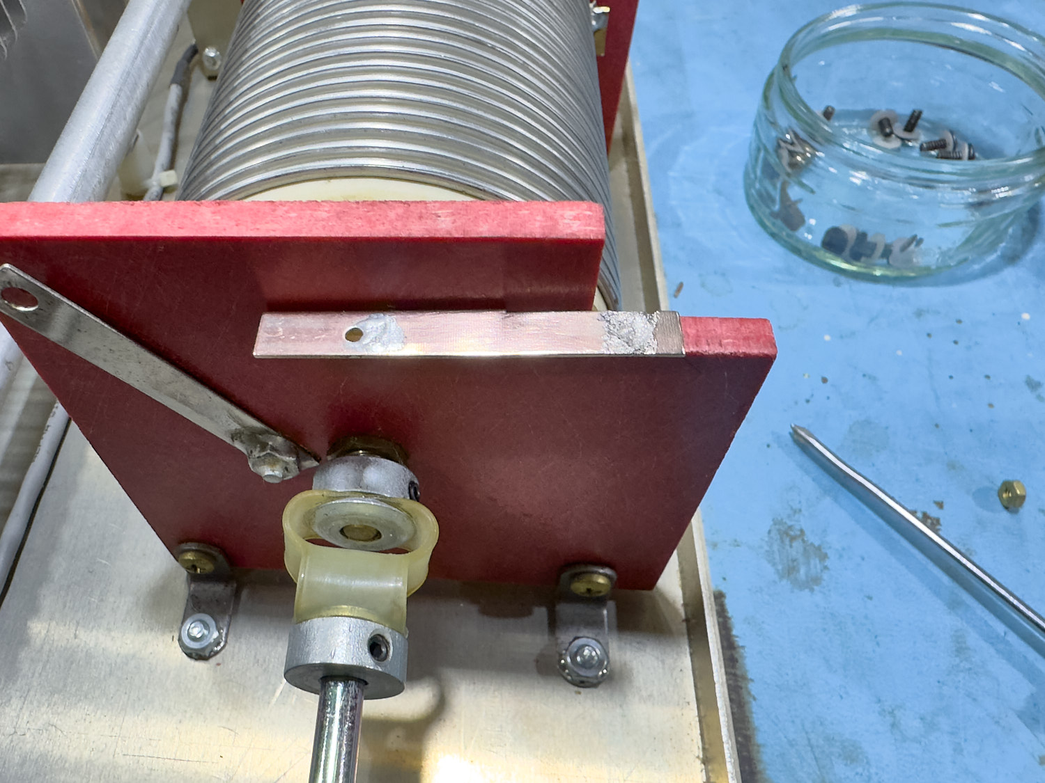
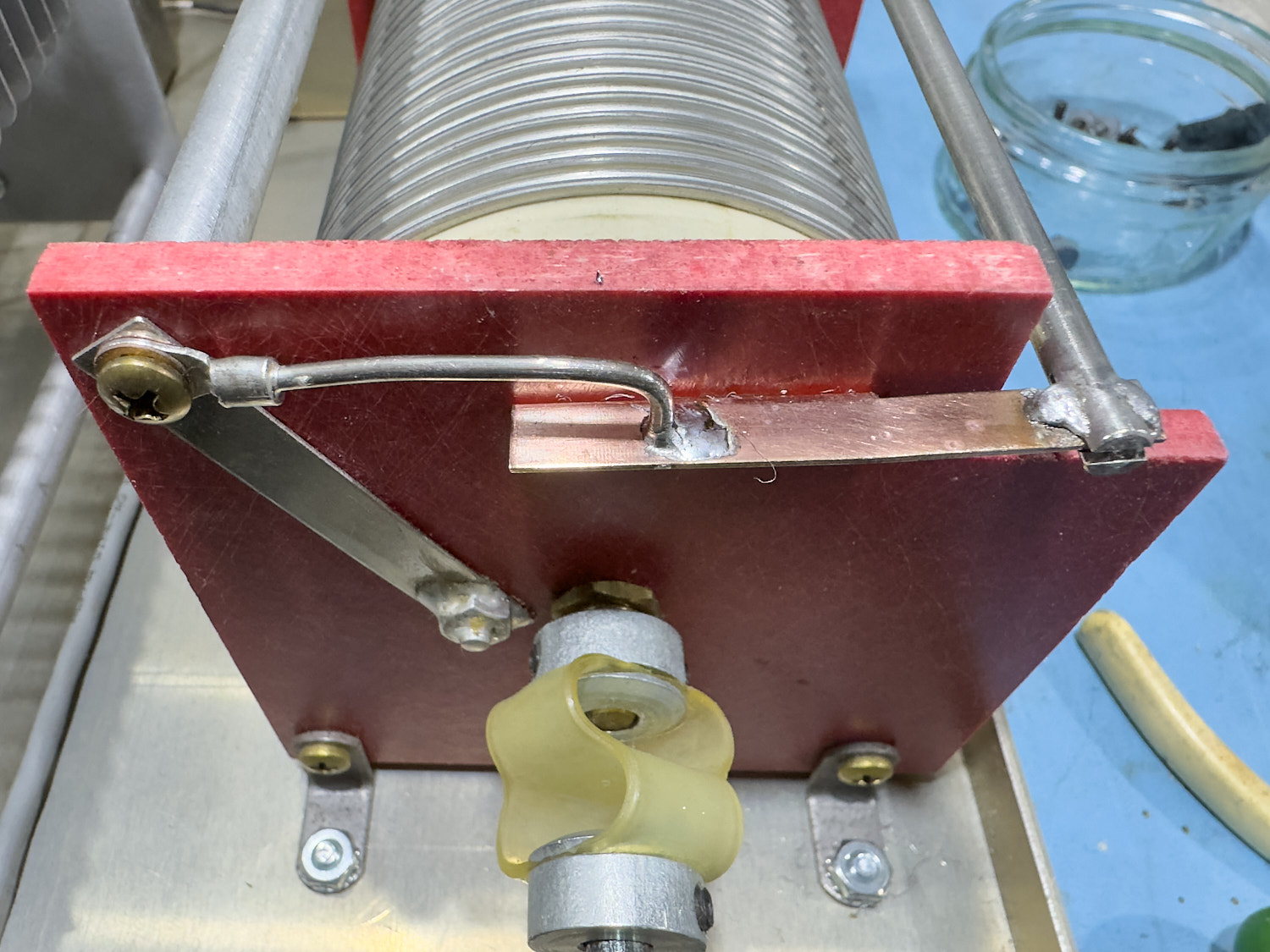
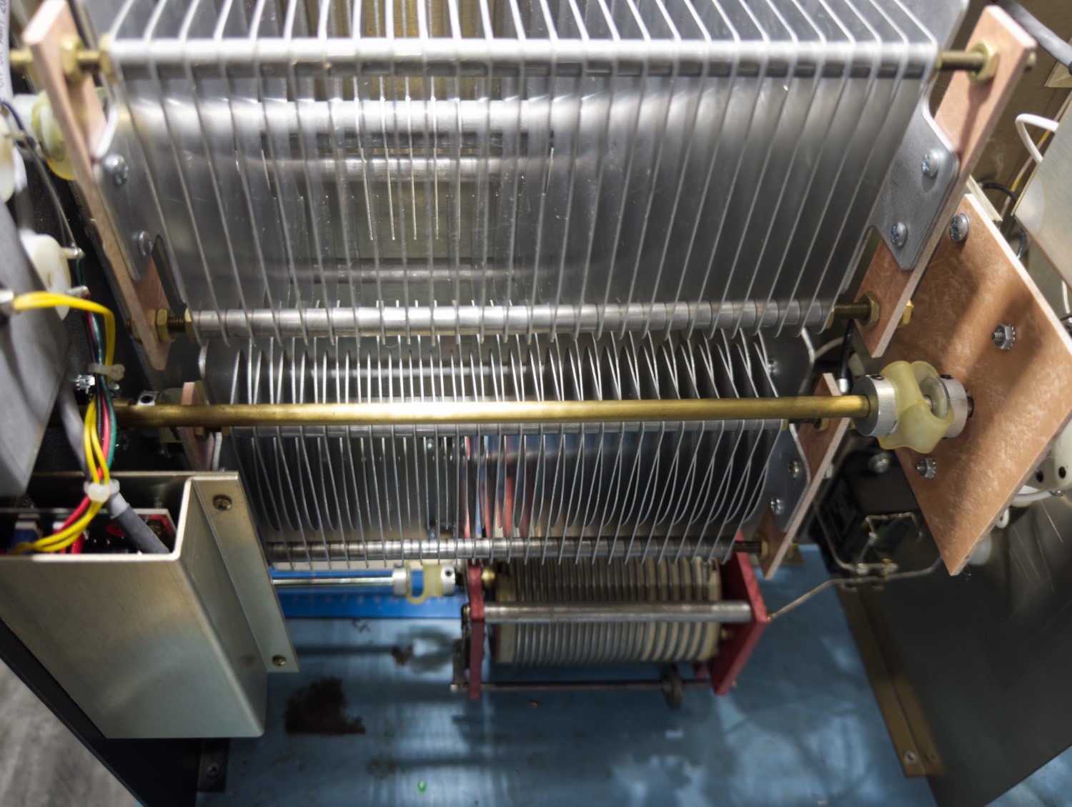
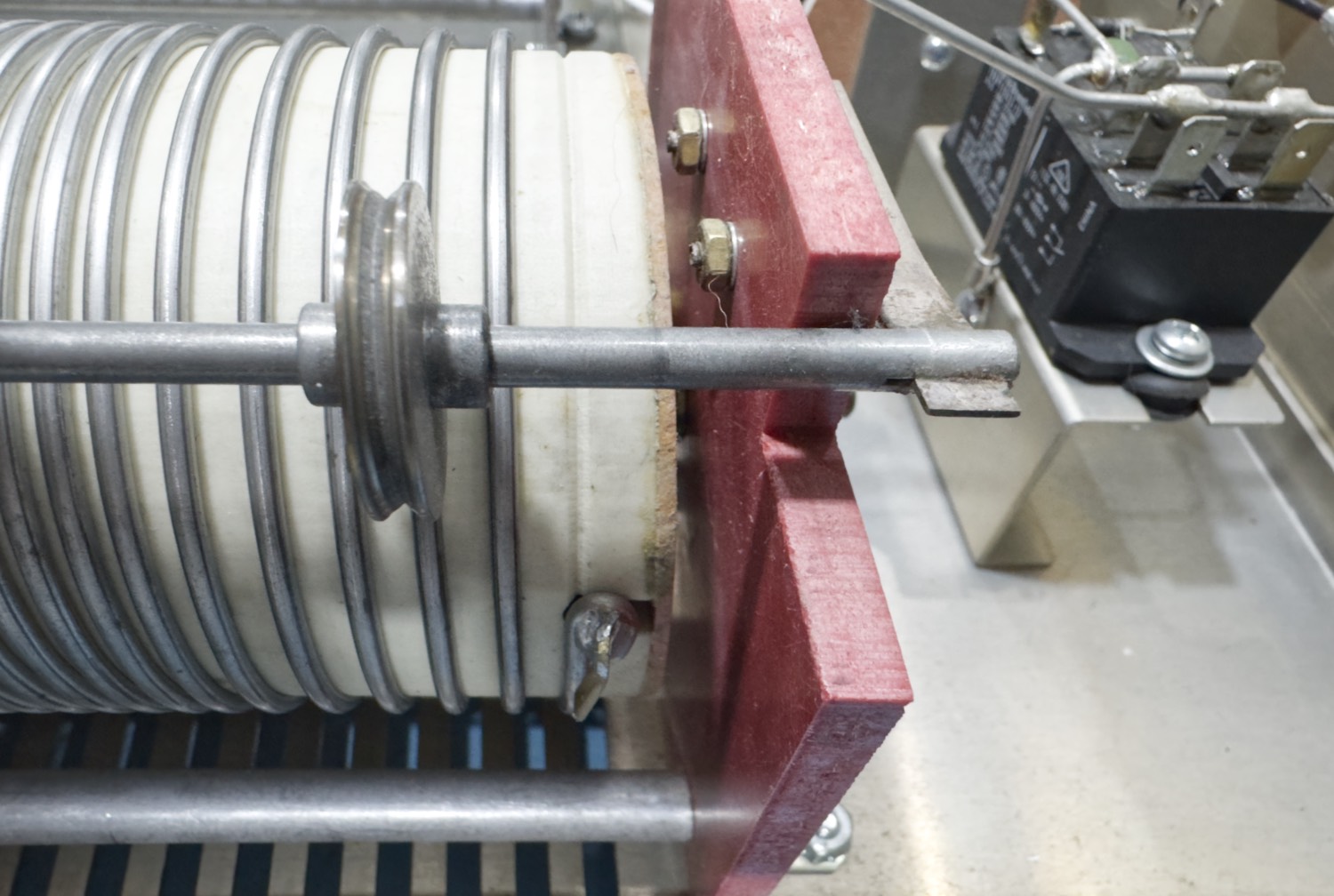
Looking at the device, and specifically the ‘Roller Inductor’, it looks as though it should be an easy fix, the contact roller, and the bar that it is attached to is only held in place by 2 screws on one end and 3 on the other so I set about undoing these first to remove the bar from the roller inductor.
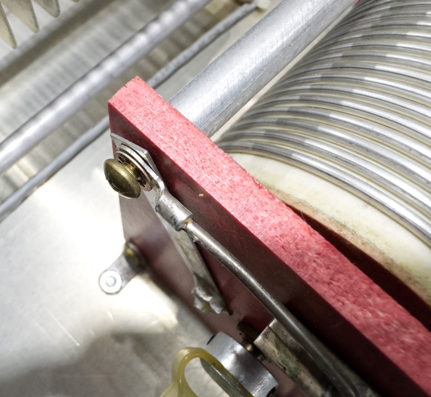
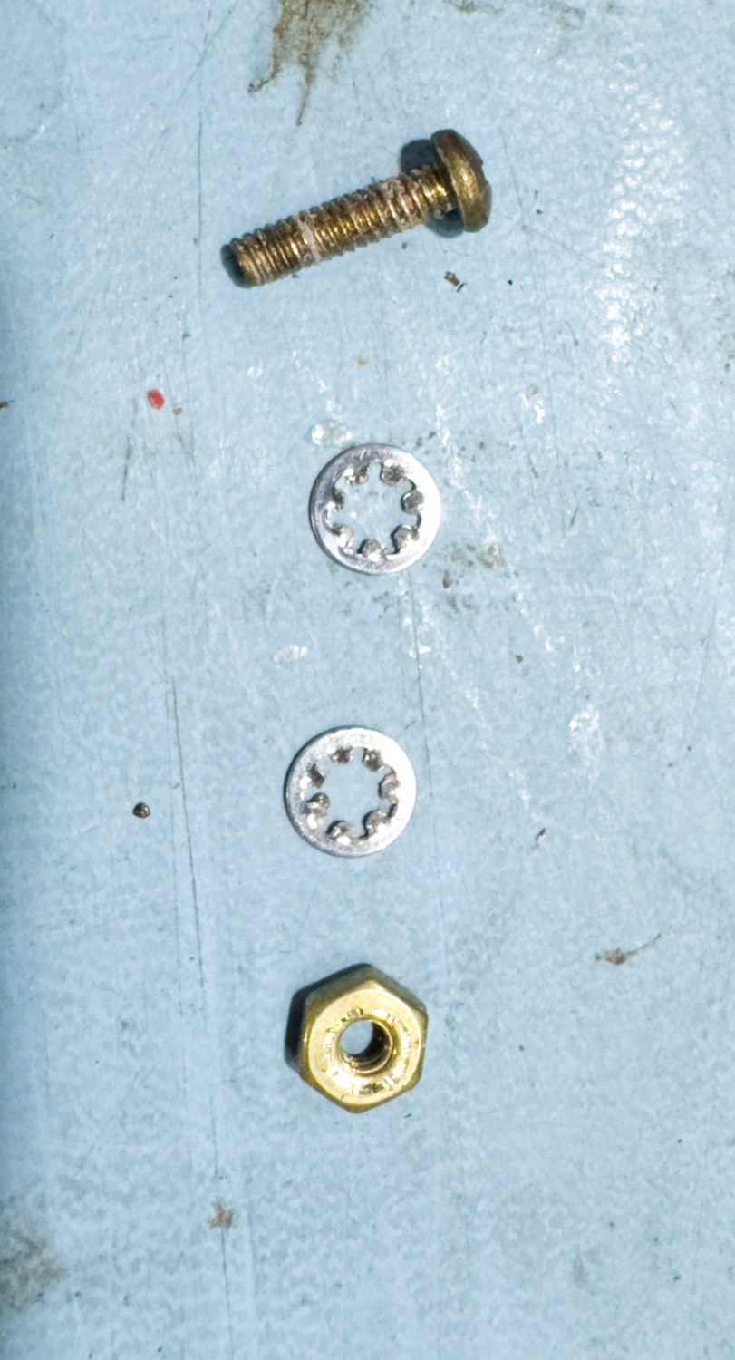
First, I removed the electrical connection to the bar that is on the end of the roller inductor nearest the front of the ATU, this is held in place with a very long screw and a shakeproof washer.
Use a small Stubby PH2 Screew Driver to remove this from the rear bar.
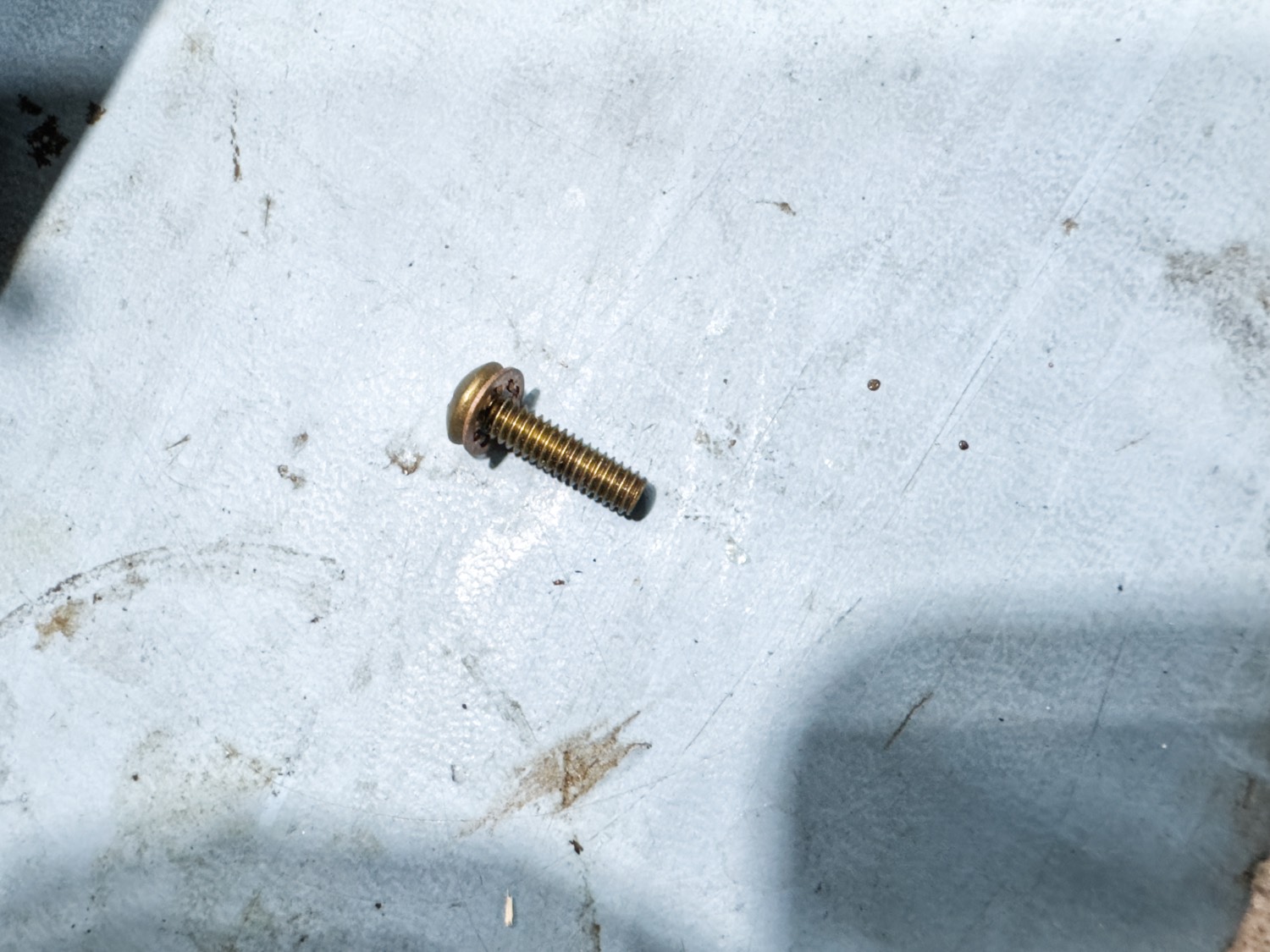
Keep the screw safe, in my case in a small pot hidden from the cats.
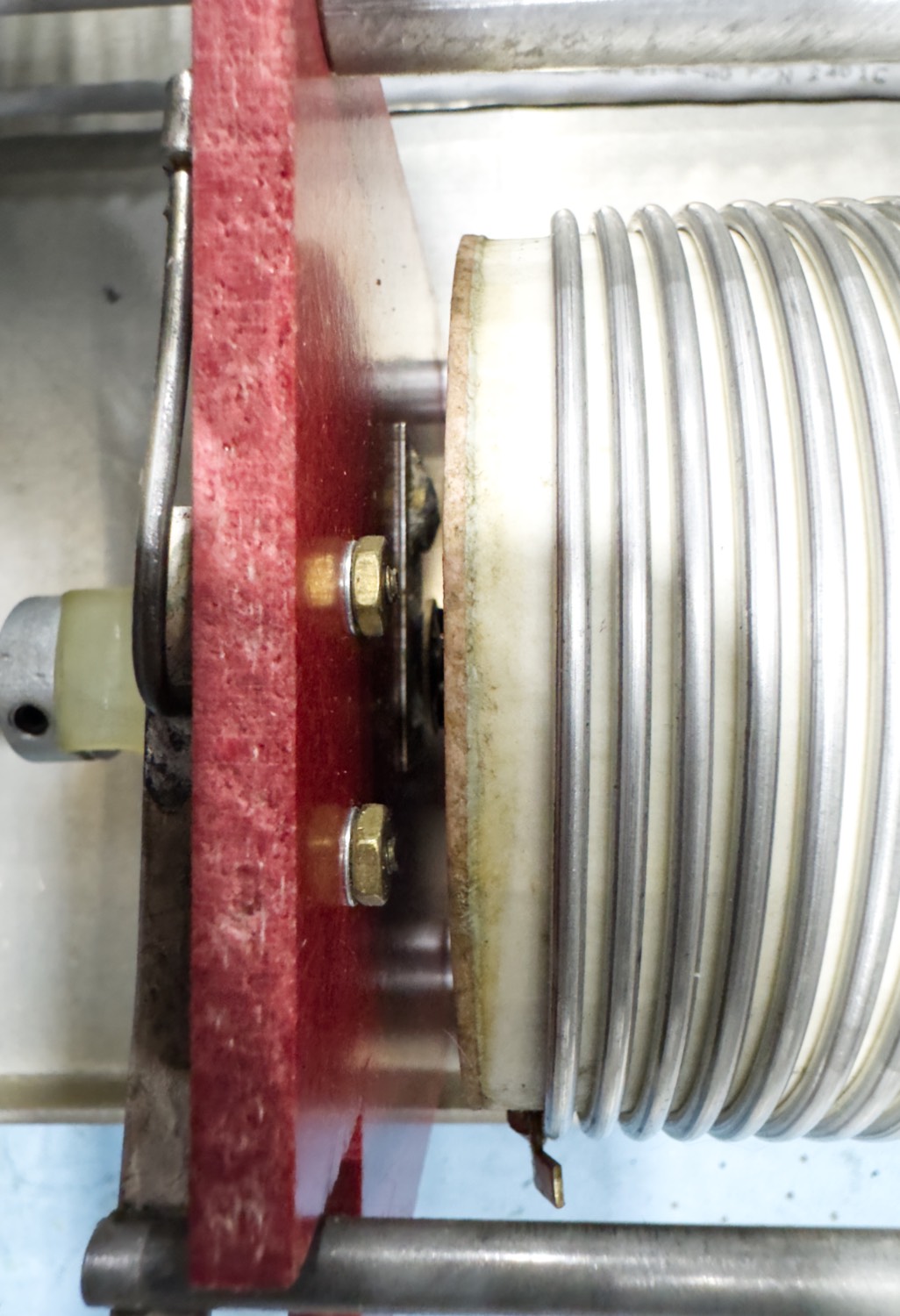
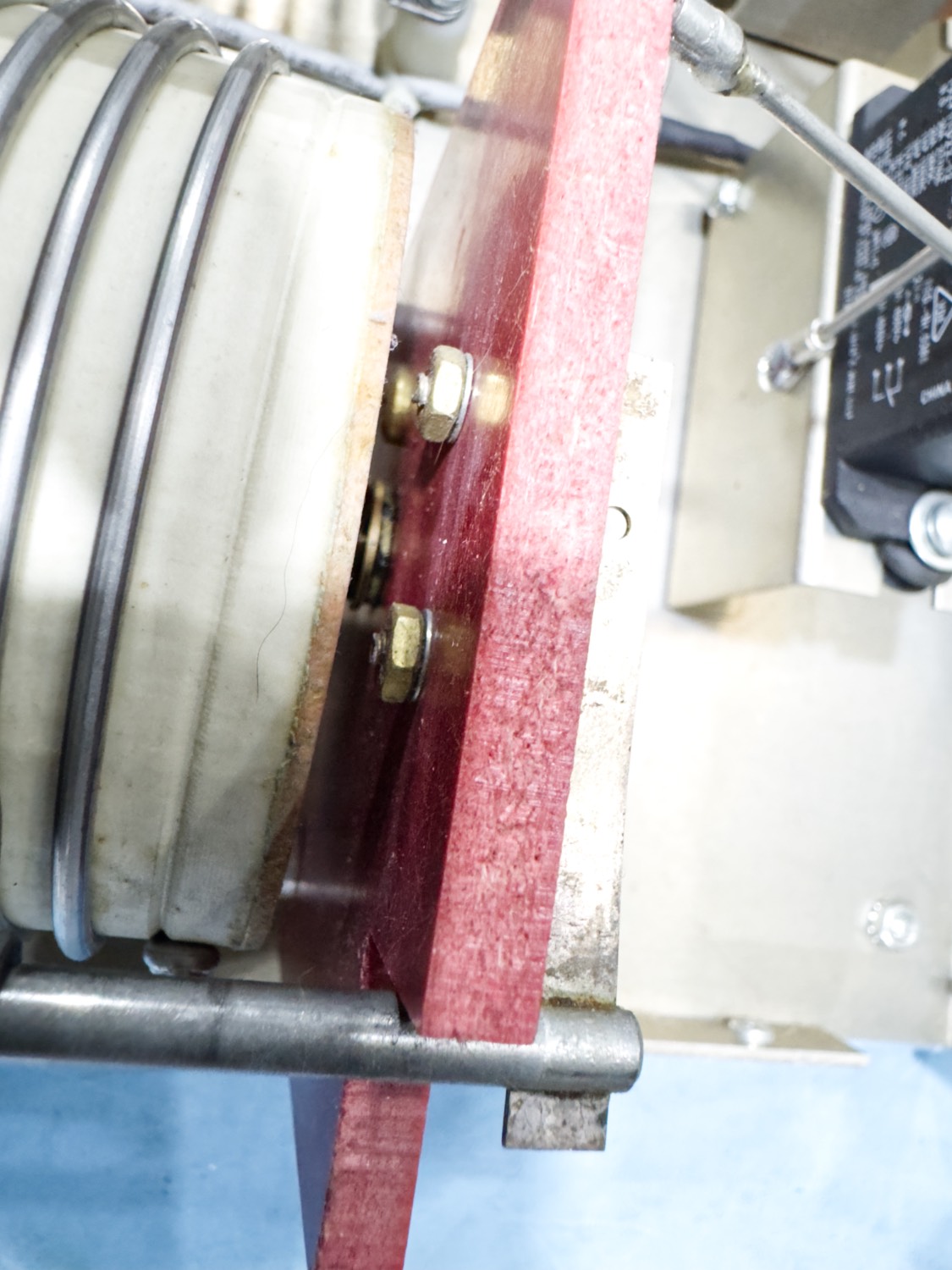
The Nuts are a bit of a pain to undo and hold on to.
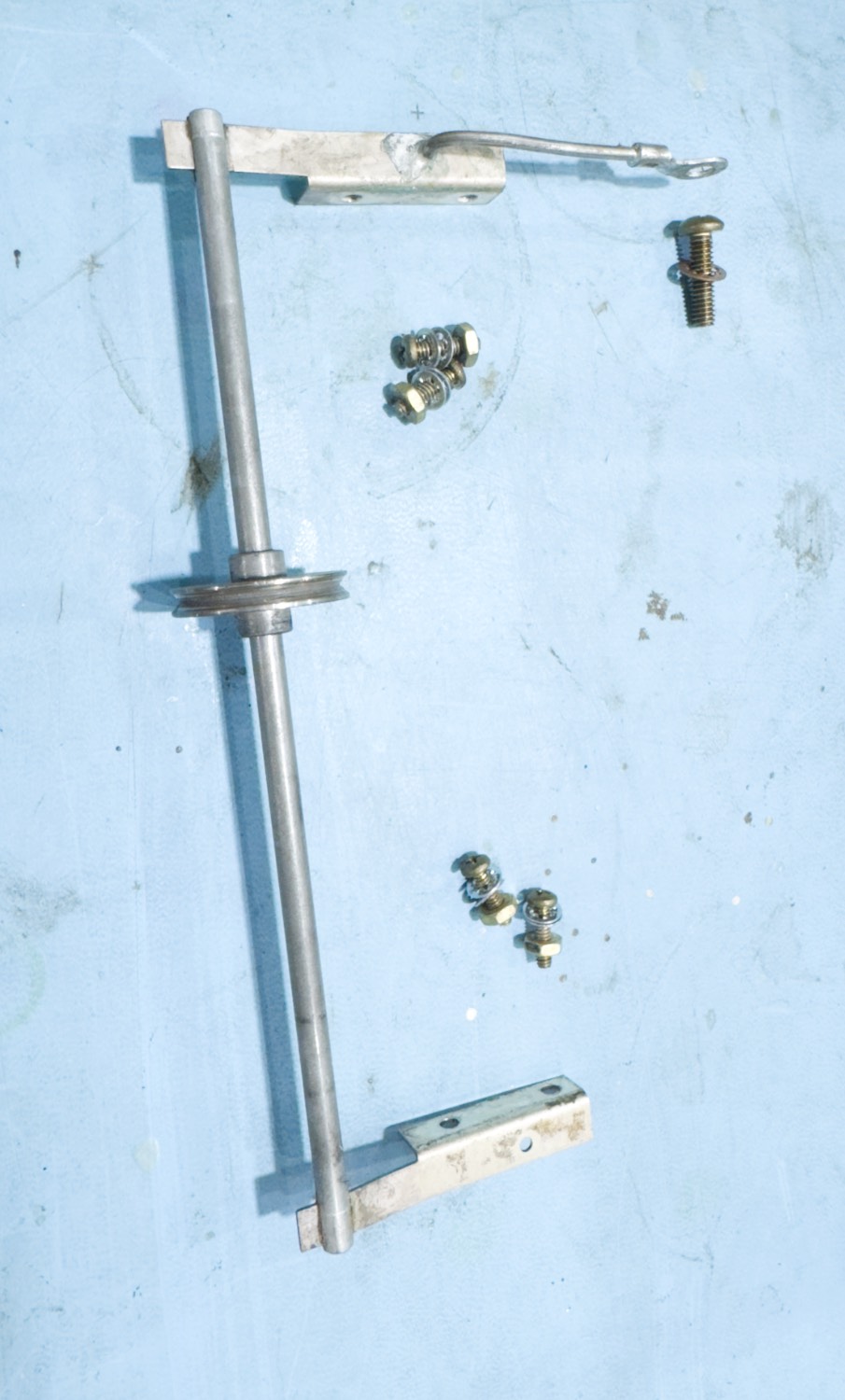
These 2 screws at each end of the Roller Inductor hold the bar in place.
The roller is then held in place by two screws at each end on the roller inductor, each of the small brass screws are fairly easy to undo, I used a small set of long nosed pliers to gently grip the nuts whilst turning anti clockwise to loosen them, once loosened I would keep the screws and the washers all together using the nuts so that I would not lose one of the parts between the time that I fix the bar and the time that I put it all back together.
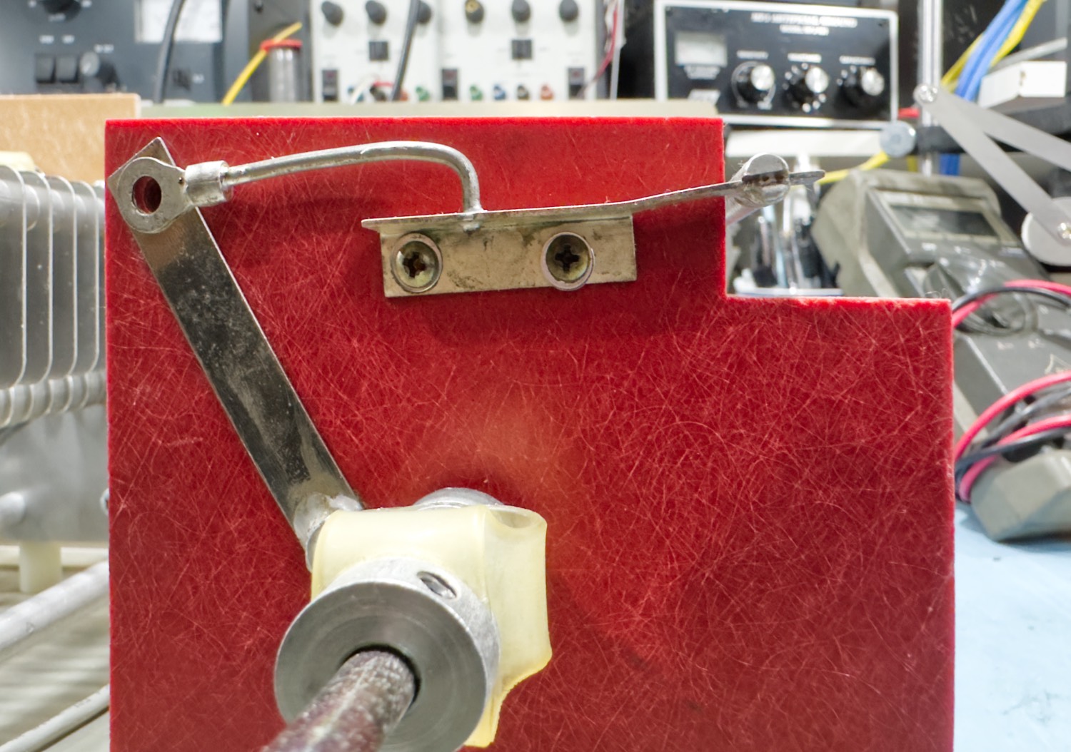
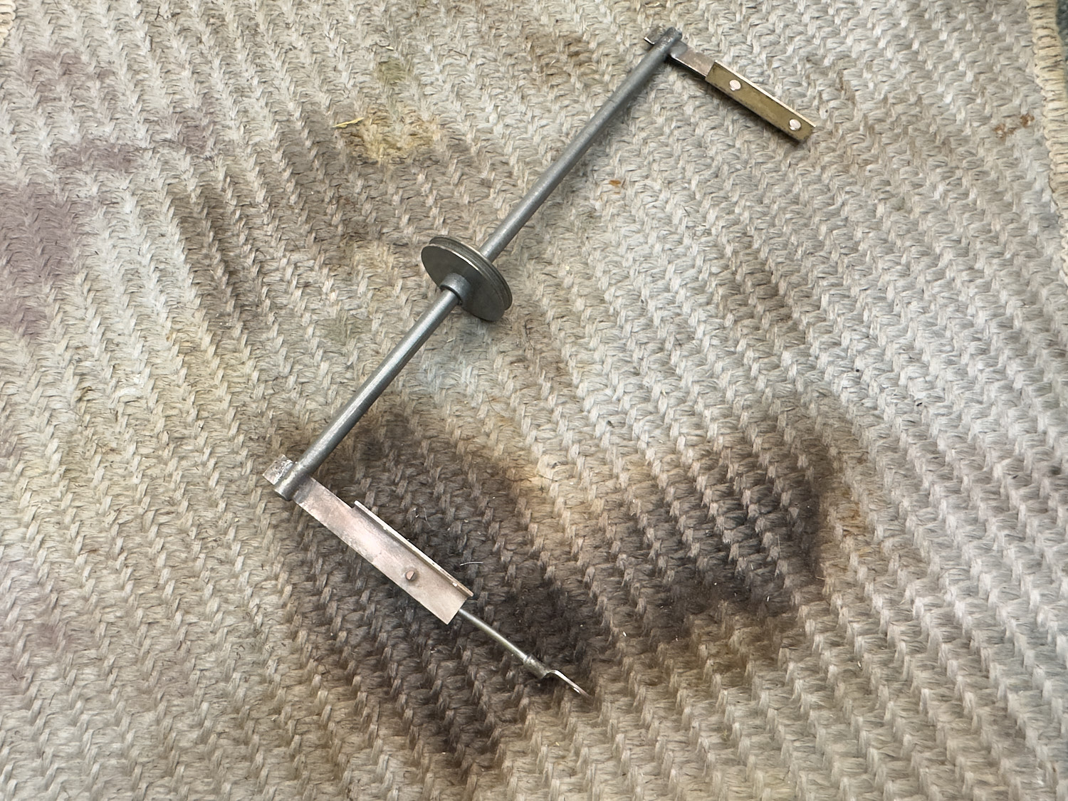
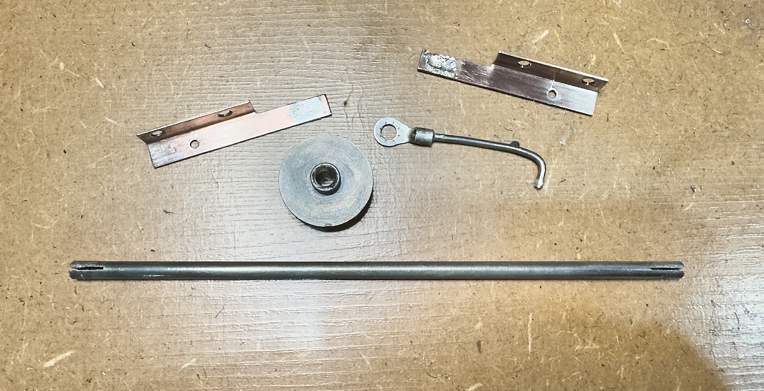
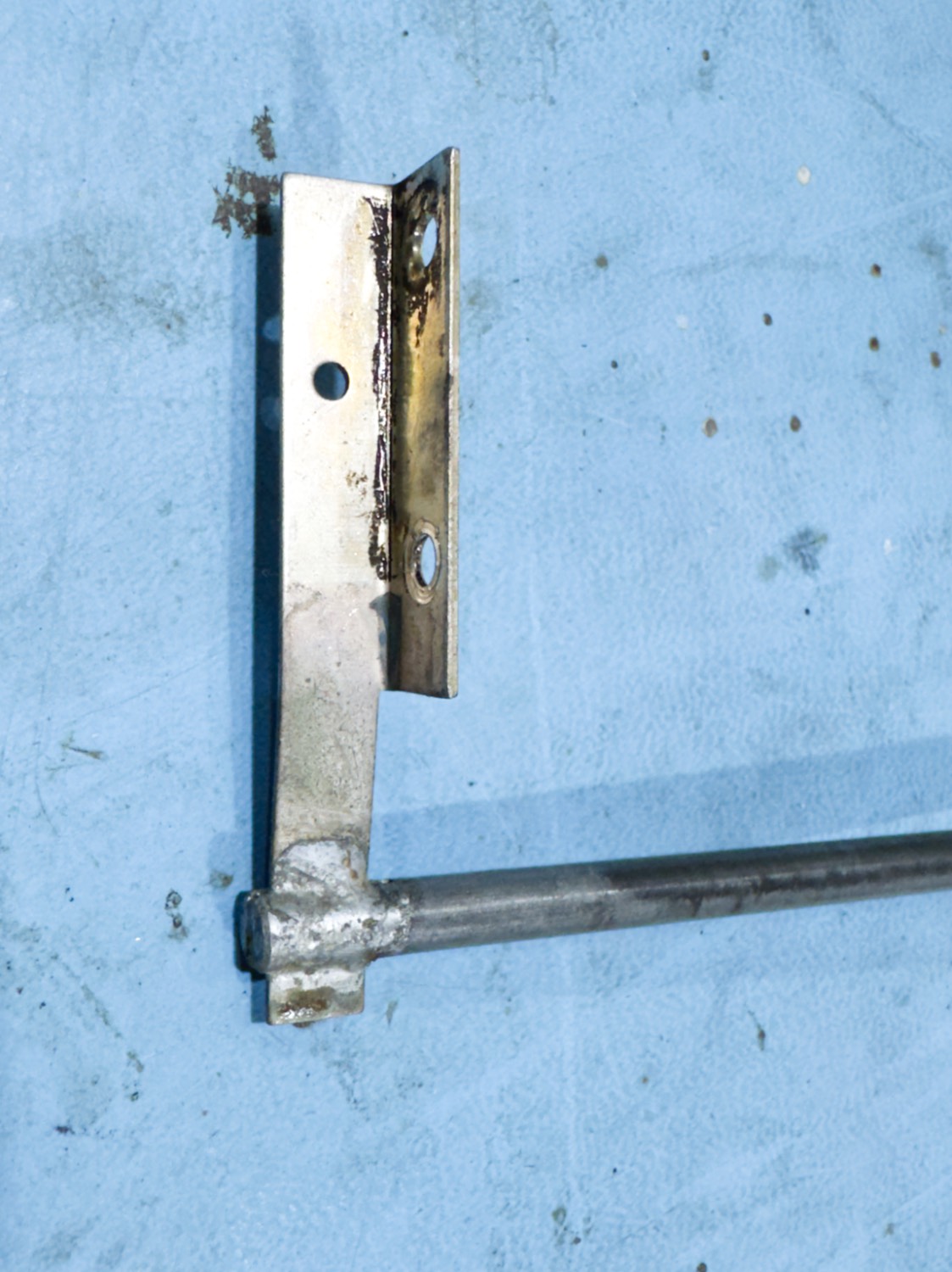
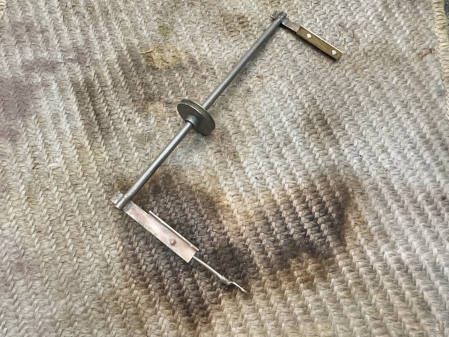
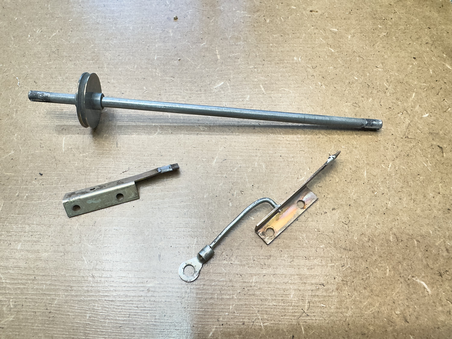
The Bar Removed - Now what to do?
Make sure you have all the parts.
The Bar Removed...
The bar can be altered by simply pushing it in more, but Palstar have soldered this to stop it from moving, so my first job will be to see if I can remove the solder from this connection.
I tried to remove the solder from this unit, but I found it near impossible to generate the heat with my poor old Weller soldering stations, even my trusty old PS-3D which has managed to be my go-to Soldering Iron for de-soldering anything until now failed to generate the heat required.
I thought about using a Dremel and small grinding bits to elongate the holes to allow me to move the bar in its present condition in a little, but whatever the metal they used here I was not getting anywhere, and 2 bit’s burnt through and no elongation done and no access to a milling machine, I think I will have to relook at de-soldering the bar again, but this time I will maybe have to resort to the soldering torch this time from the plumbing box.
stumped, I did find a wire brush and I applied this to the side and it looks as though the metal is in fact copper, a soft metal! At this moment I have zero idea where any needle files are so I may have to make a trip out to get some from B&Q so I may just have to wait a few days till I get chance to collect some. I am left with 2 ways of sorting this out, I either take some needle files to the 2 holes in each end and make them into slots, or I find my plumbing blow torch and de-solder the bar from the 2 end bits, both ideas have pro’s and cons.
I decided whatever the troubles that I am going to get into I would take a blow torch to the ends and see what they fall apart like once some heat is applied to it. If it goes wrong, I am sure that I have another Roller Inductor that will do in this ATU.
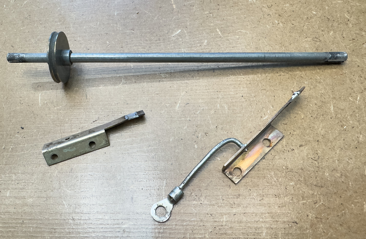
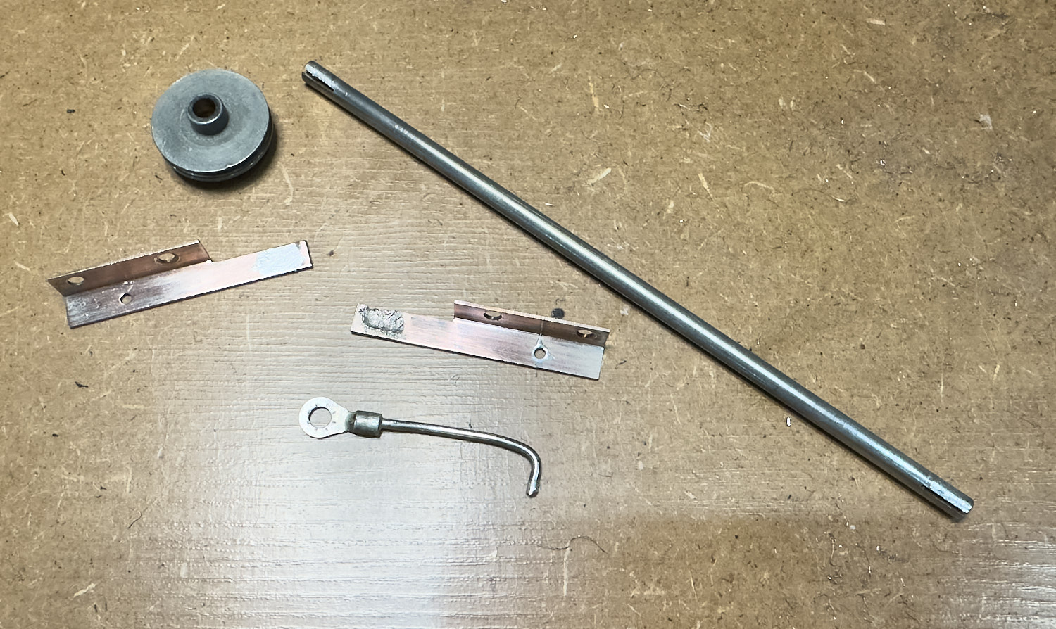
I was actually quite surprised at just how easy it was to separate all the parts. I must have only just touched the ends for a few seconds and the copper mounting bits just fell away from the bar. It took a little bit of cleaning with some wire wool until the pully wheel fell off the bar that it sits on, as for the slot though this would take a bit more attention.
When the end bits fell away from the bar it left quite a bit of solder still in the slot, I tried various methods to remove the solder ad in the end the best method that I had was to use the blow torch again and just heat up the end of the bar just enough to tap it on some wood so that I could get most of the solder out of the slot.
To get the rest out I found that a Scalpel was the best tool, it just cut just enough out.
I spent quite a bit of time cleaning up the bits as best I could with the wire wool, I decided to leave a fair amount of solder on the end plates as this would come in useful later.
Everything Cleaned read for reassembly.
Putting it all back together was a real pain!
Take your time and it will work out.
I did not think that the reassembly of the Roller Inductor was going to be as bad as it turned out to be, there was the obvious issue of not having enough hands. Putting the screw and a single shakeproof washer through the plate and through the red end plates was obviously the easy bit, but as You cannot get to the other side with fat fingers you are left to gently grip a shakeproof washer and ever so carefully hock it onto the end of one of the screws, and I found that it is best just to do one screw at a time, after this you need to get a small screw driver to hold the screw in place whilst with a set of fine long nosed pliers you gripped a nut and with a little luck you can put it onto the thread and tighten it up just enough to know that you will not lose the nut somewhere in the bottom of the ATU.
That's the horrible bit done.
The next bit you must be a little careful about. First job is to place the bar against the two plates and see which way round best fits the slots in the bar, once you have worked this out gently tap the bar at each end just enough to make sure that the roller fits against the inductor coil. Because I had left a small amount of solder on the end plates and even in the slots that when you tap the bar into place it stays there meaning that you are able to take your time here.
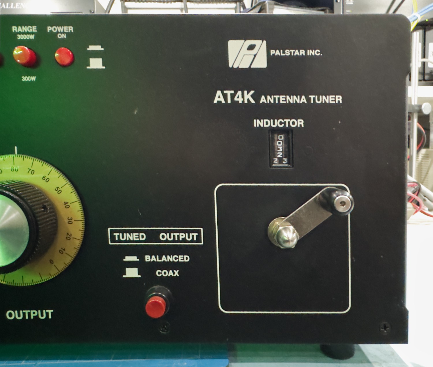
You need to make sure that you are happy with the read-out on the front panel, I tried to get it to start at zero but I could not get this to work, I settled for 10 onwards, also making sure that the numbers went the correct way, it will be a real pain if it started at 10 and went backwards to 834 for instance.
The next task is to get the same amount of friction throughout the entire length of the inductors coil, thankfully because of the solder left on the parts this was quite easy to do by running the roller from one end to the other, a light tap or two with the small hammer and the repeat until you are happy with how it is working.
All ready for the solder.
Just add just enough solder to hold the bar in place.
When you are totally happy about the tightness of the fit you can start to apply some heat to the parts that require soldering, for this I used my trusty old Weller to solder the bar to the two end plates, now be careful not to apply too much solder here, i.e., only put just enough to hold it in place, do not flood the it as you may need to have another go at this in a year or two. My soldering here is not my best, trying to apply solder to whatever the bar is made of and the copper side plates I did not want anything more than a basic electrical connection, the lid is going to be on the ATU so no one is going to see it
Now before I move on to finish this off I just run the inductor again to make sure that it is still the same and that there are no lose spots over the travel of the roller inductor, if this is Okay then we can finally put the long screw back into the remaining hole completing the electrical connections.
Now to just put the cover back on and test with a radio connected.
I am now retired and living on the Isle of Man, my background is as varied as it gets, ranging from Information Technology to Graphic Designer and 3D VFX Artist, using and teaching Autodesk Maya, Softimage, and Smoke, one of more enjoyable positions. Since Moving to the Isle of Man I try to keep myself to myself and work on the house, I don't do much with regards to Amateur Radio or Electronics anymore, but I am still interested in the hobby and may well get back into it one day....