The Microcode Morse Code Reader Electronic kit assembly instructions
There are many Electronics Kits out there that are very useful for us Amateur Radio enthusiasts, but a lot of these are somewhat too simple and not really as good as they make themselves out to be, or way too difficult for the average newbie who is either just wanting to get into building something for his hobby or even using it a project piece for the Intermediate exam.
I rate this kit as ‘Easy’, this means that any users out there should not get out of their depth when taking this one on, so long as you can hold and use a soldering iron; you should find this fun to build.
The build time for this should be easily within a day, but again if you are new to this, take your time; it is not a race to finish it faster than anyone else out there as this only causes mistakes, if it takes you a week to build then at least you had a weeks’ worth of fun building it, surely that’s worth it…
Please Note: As with most of the images on my site, if you click on them you will get a larger image to help you see what is happening, these can then be saved to your local HDD. If you are wanting to use them on your site, then please put a mention to me on the site..
The Microcode Morse Code Reader kit arrives through the post, well packed in a jiffy bag, open this up and you will see a large zip lock plastic pocket with the PCB and the instructions staring at you and eager to get out…
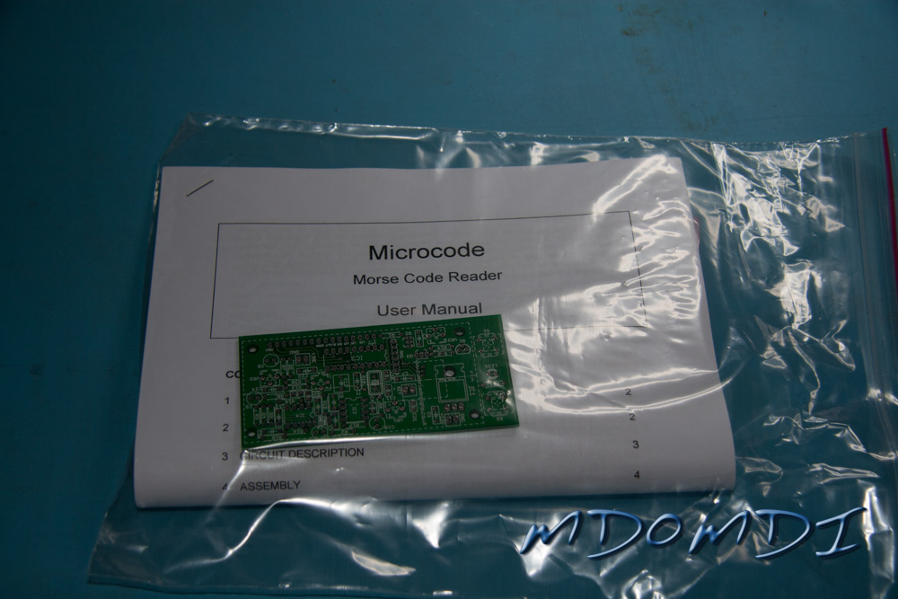
Before you even power up the Soldering Iron, make some space in the shack, put the coffee on, kick the cats out and shut the door, then take out the contents of the pack and read through the enclosed manual.
I will say that unlike some kits, this manual is actually easy to follow, and I don’t think that anyone that is new to building kits will have any issues with this kit at all, once you have read the manual go to page 15 of the manual (this might change if they change the manual) which should be the Parts List.
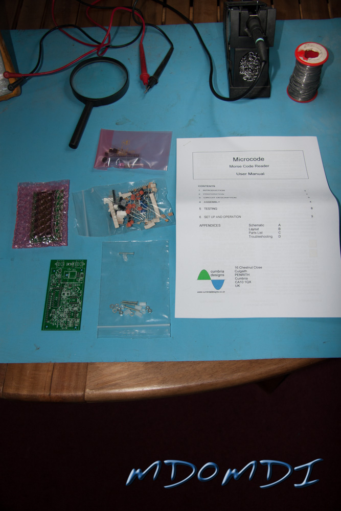
Lay everything out on the bench into piles so that you can check everything off. If again you are new to this hobby, I have hopefully made the following notes to help you out.
Microcode Morse Code Reader Kit Parts List
1 x 15Ω Resistor
1 x 100Ω Resistor
2 x470Ω Resistors
1 x 1kΩ Resistor
1 x 2.2kΩ Resistor
1 x 4.7kΩ Resistor
8 x 10kΩ Resistors
1 x 47kΩ Resistor
3 x 100kΩ Resistors
1 x 220kΩ Resistor
1 x 10kΩ 6-way Resistor Pack
4 x 10kΩ Variable Resistors
1 x 10nF Ceramic Capacitor
2 x 10nF Ceramic Capacitors
9 x 100nF Ceramic Capacitors
2 x 10nF Ceramic Dipped Capacitors
1 x 100nF Ceramic Dipped Capacitors
1 x 0.47μF Polyester Capacitor
1 x 1μF Polyester Capacitor
4 x 100μF Electrolytic Capacitors
2 x 1N4148 Diodes
1 x 3mm Red LED
1 x 2N3906 PNP Signal Transistor
2 x 2N7000 N-Channel FET’s
1 x MDLS16265 16×2 LCD Display Unit
1 x NE5532N Op Amp
1 x LM567N Tone Decoder
1 x 7805 Voltage Regulator
1 x PIC16F628-I/P PIC IC (Pre-programmed)
3 x 2-way Headers
3 x 2-way Connector Shells
2 x Push Switches
1 x 16-way SIL Socket
1 x 16-way Pin Strip
2 x 8-way DIL Sockets
1 x 18-way DIL Socket
1 x 20 MHz Crystal
1 x Electret Microphone
1 x PCB (version 3.0)
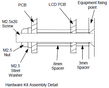
4 x M2.5 x 20mm Screws
4 x M2.5 Nuts
4 x M2.5 Washers
4 x 8mm Nylon Spacers
4 x3mm Nylon Spacers
Tools Required
Temperature Controlled Soldering Iron
Fine 60/40 Rosin Cored Solder (Please don’t use that lead free crap!)
Fine Side Cutters
Small Long Nosed Pliers
Solder Sucker (Just in Case)
Digital Multimeter
Magnifying Glass with Lamp (Not essential but very useful if you have one to hand)
Anti-Static Surface (Again not essential but very advisable)
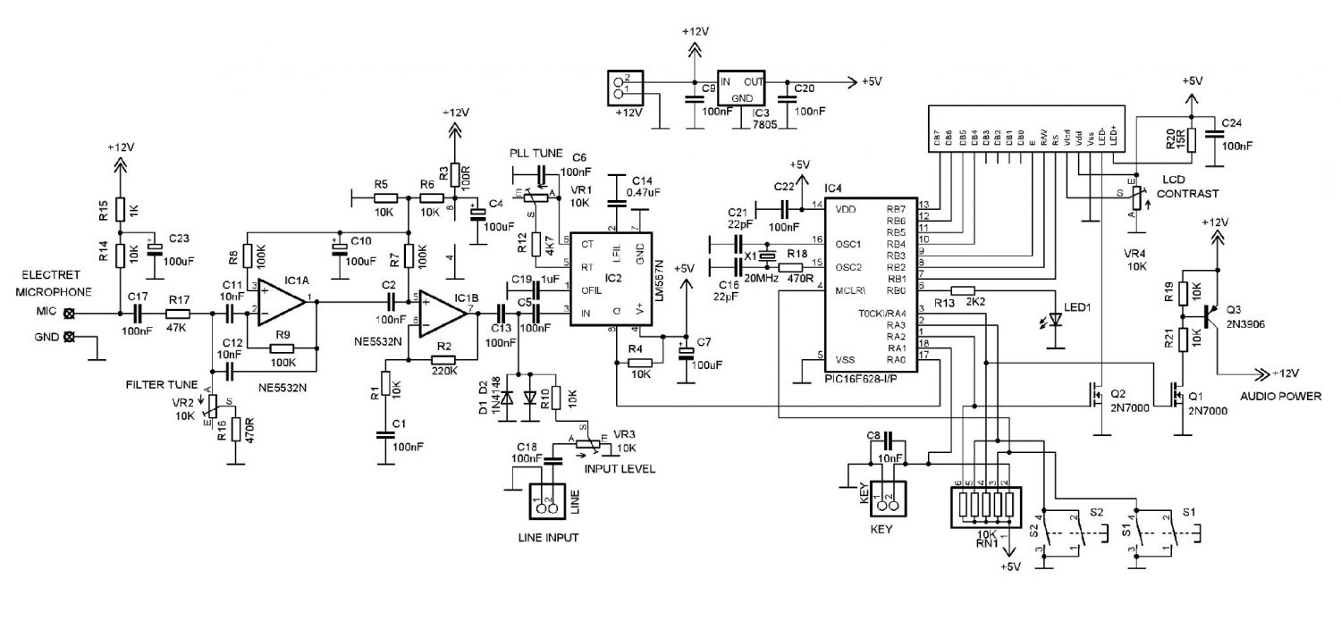
Schematic Diagram
Board Layout
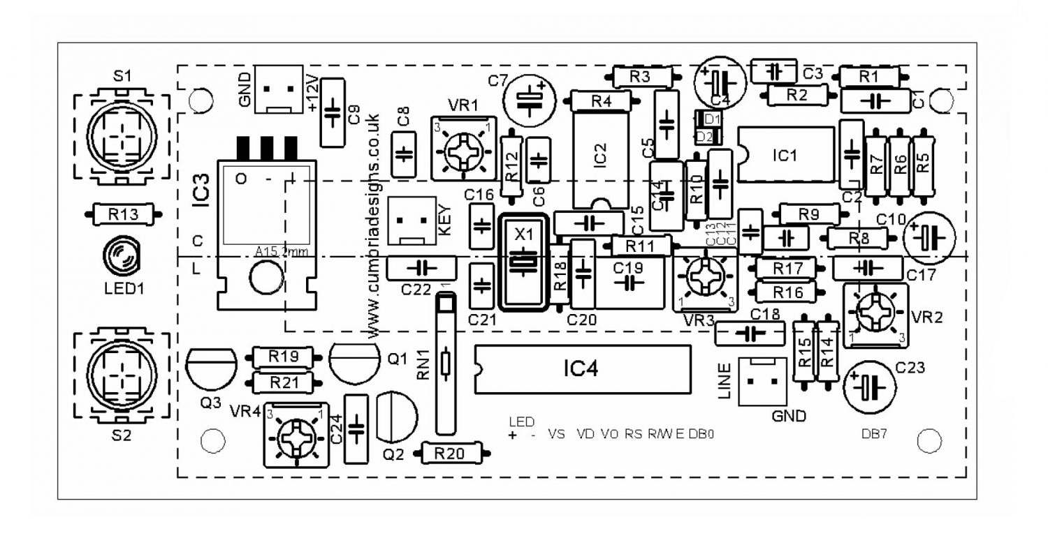
Most of the following information is taken directly from the documentation supplied by Cumbria Designs, and is very well laid out and also very easy to follow.
Audio from the electret Microphone is filtered and then amplified by IC1 and then passed to the PLL tone detector IC2 for conversion to logic level keyed states. The simple input filter provides some rejection of unwanted ambient noise picked up by the microphone.
The filter centre frequency is tuned by VR2. An audio tone falling within the capture range of the PLL causes the PLL output to go low. The detection frequency of the PLL is set by VR1.
This is adjusted to the mid-range of the preferred audio frequency of the incoming Morse Code.
The bandwidth of the PLL is very narrow, offering good unwanted signal rejection and a degree of resilience against noise. The logic output levels of the decoded Morse Code are passed to the processor where digital filtering is applied to greatly enhance immunity to noise. The processor measures the duration of the detected Morse Code elements and by comparing each element duration against a running reference, determines whether the signal represents a dot or a dash.
Each character is built up from a series of dot and dash signals to form a binary address which, when an end of character state is detected, is used to address a table holding corresponding ASCII characters. The ASCII text is passed to the LCD for display.
The Key input allows a Morse key to be connected to the Microcode for training purposes.
In Key mode the Audio stages are disabled. The Key should be a “volts free” device, i.e. a direct contact such as a high speed relay, an NPN transistor open collector or N channel FET drain. A 10K pull up resistor holds the key input to the processor high at 5v whilst the key is in the open state. When the key is operated, the input is pulled low to ground representing a “key down” state.
The speed of the incoming Morse is calculated from the running reference value. This provides the speed in Words per Minute (WPM) based upon a standard 50 element word (PARIS) and the average element duration. The speed reflects the equivalent speed that the element duration would yield.
Be aware that badly sent Morse or Farnsworth style sending with long durations between characters will produce a WPM display not representative of the actual throughput.
Assembly
The assembly of the board is very straight-forward and should not cause you any issues at all.
Please make sure that you follow all of the instructions and if possible read through each section twice to make sure that you fully understand the instructions to save making any mistakes.
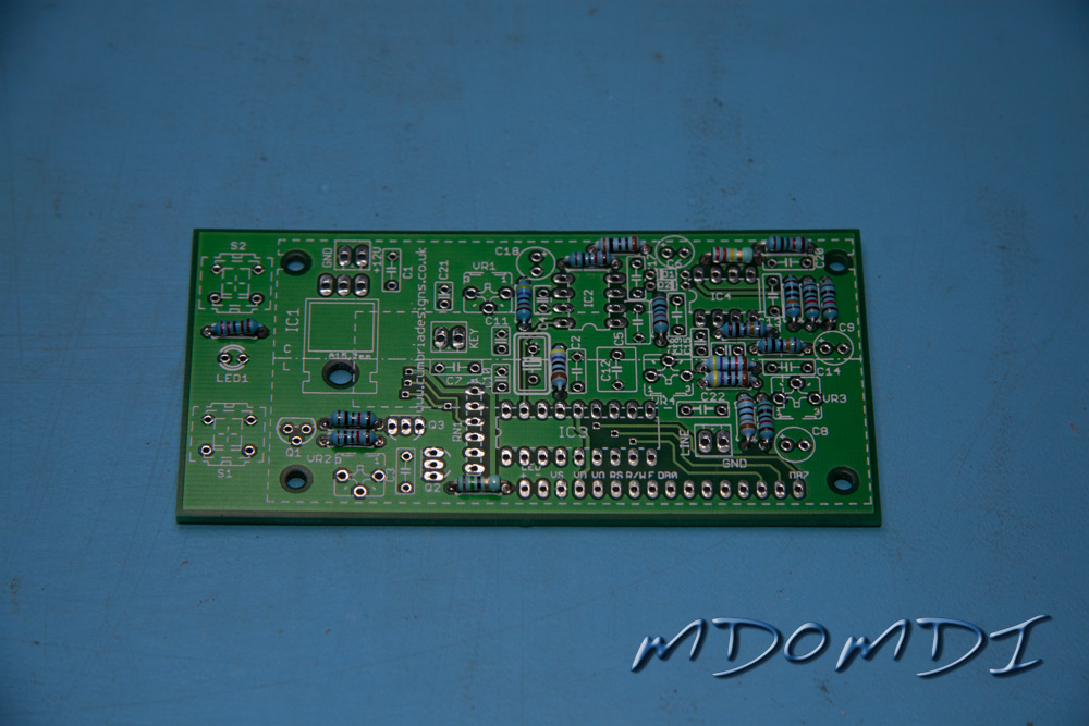
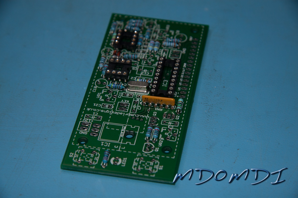
Install the fixed resistors onto the PCB, the instructions in the manual here are very easy to follow and as long as you can see the colours on each resistor, this part of the build should not prove too difficult.
If however you are getting a little lost, use the resistance setting on your Digital Multimeter to help clarify which values are which, some of the colours can be a little hard to read, such as the brown and red for instance.
You now have to install the two 1N4148 Diodes.
Please note that these must be installed the correct way round, Board Layout supplied in the manual (page 14) displays the orientation very clearly so you should not find this too hard, but make sure you have the black band on the actual Diode positioned at the same end as shown on the Board Layout.
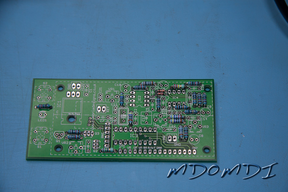
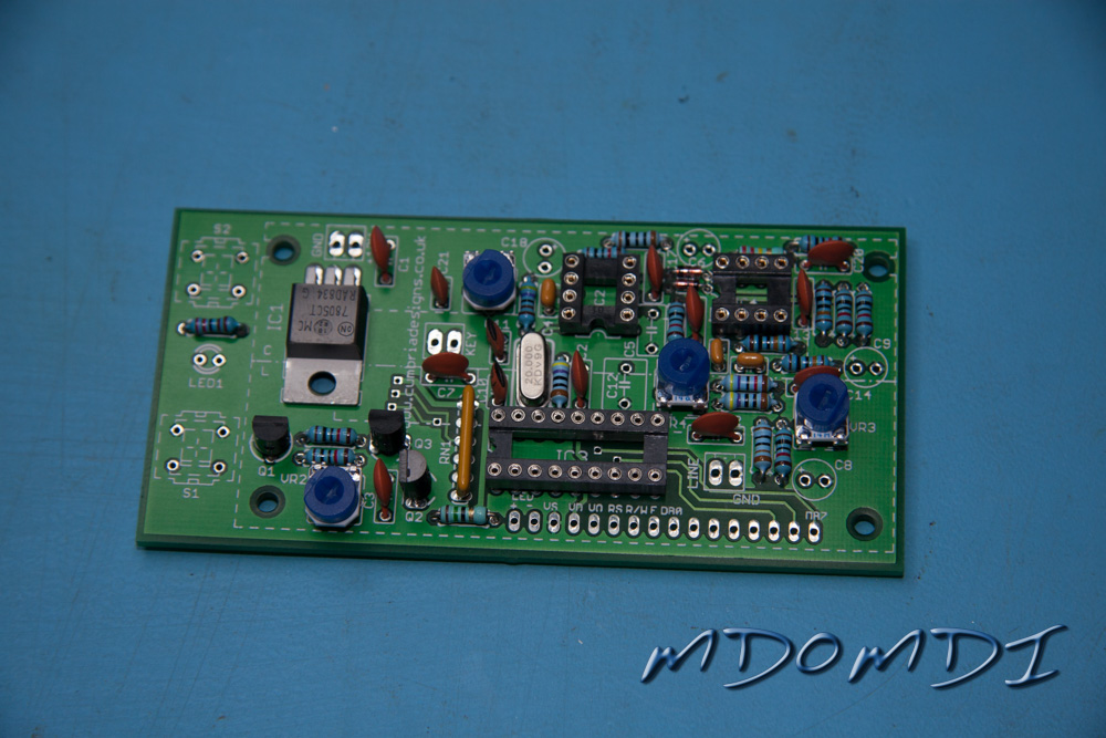
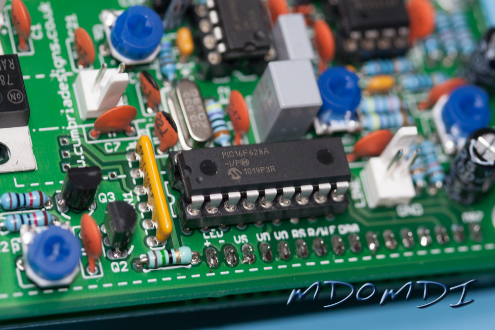
You are then asked to install the SIL (Single in-line) Resistor Pack.
This needs to be installed the correct way round, you will be asked to make sure that the text on the component is pointing towards Q2 and Q3. I have marked these on the photo to aid your installation.
You now have to install the 20 MHz Crystal, this item can be installed any way round, but it is a little sensitive to heat, the easiest way to install this item is to just solder in one of the legs whilst holding the crystal from the other side of the PCB with your finger, once the solder is solid, you can then turn over the board and see how close the crystal is to the PCB, it ideally needs to be around 2mm away from the PCB, quickly re-heating the solder and either pushing or pulling the crystal and then letting go with the soldering iron will enable you to place this just right.
Once the height is set correctly the remaining leg can be soldered into place.
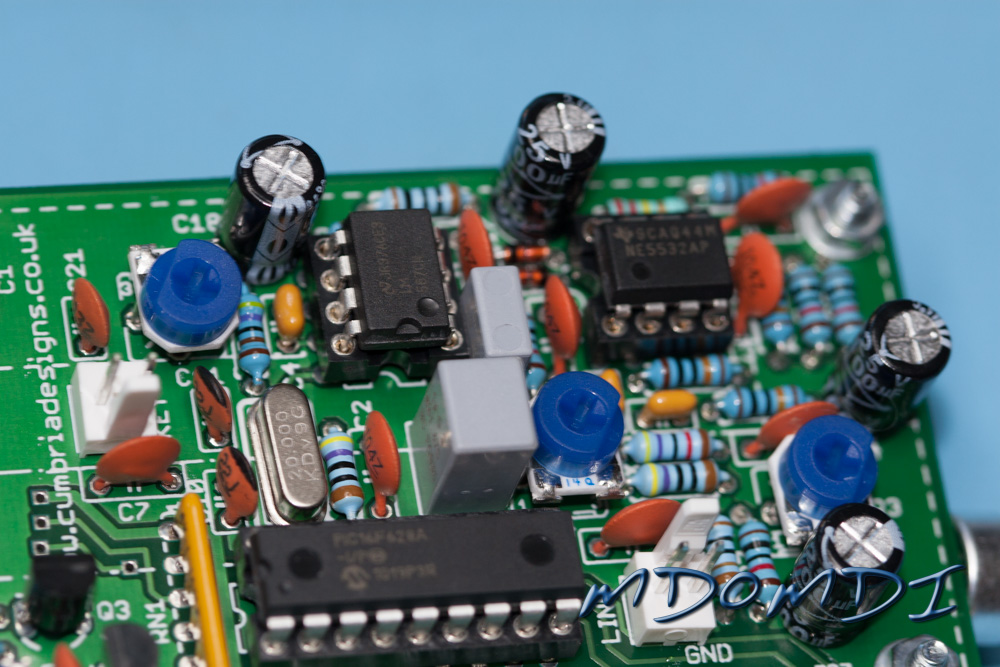
Now install the three Ceramic Dipped Capacitors.
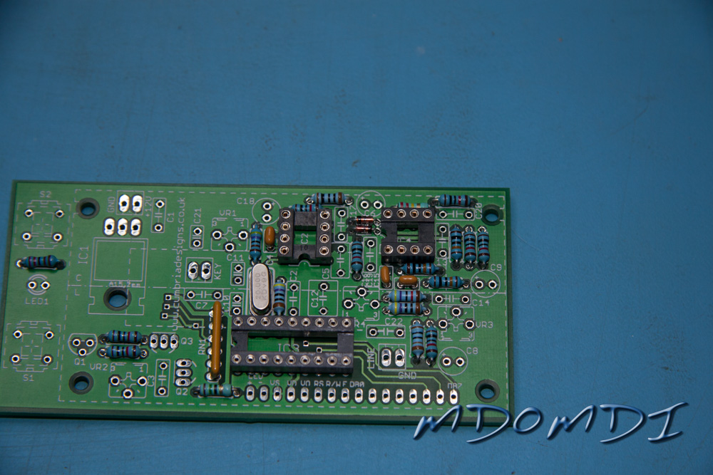
Hopefully you will not find it hard to work out which value is which here, the markings on the capacitors are usually quite easy to read, even if you cannot quickly work out what the values are, thankfully in this case you have two values of one size and then one different value as well so they should be easy to work out which is which.
Again the instructions in the supplied manual are very thorough and explain the values very well.
Work out the values of the Ceramic Disc Capacitors and place them into piles, this will make sure that you do not make any mistakes when you come to solder them into place.
Solder in C10, C11 and then C21, this will get these values out of the way, then the only ones left are the 100nF Capacitors.
Now install the remaining Ceramic Disc Capacitors.
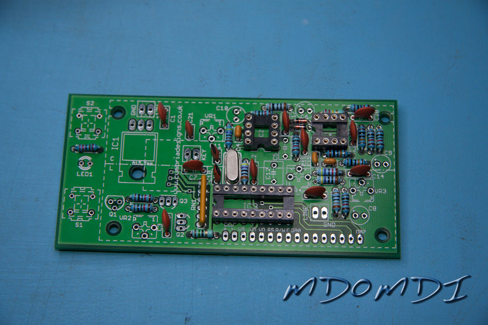
Make sure that you Discharge yourself before picking up this component, although transistors are fairly stable, it is better to be on the safe side.
Now install Q1, this is the 2N3906, you should be able to read the markings on the flat face fairly easily with the aid of a Magnifying Glass.
Make sure that the orientation of the transistor is the same as marked on the PCB by the Silk Screen.
Now install Q2 and Q3, these are the two 2N7000 FET’s.
Make sure that the orientation of the transistor is the same as marked on the PCB by the Silk Screen.
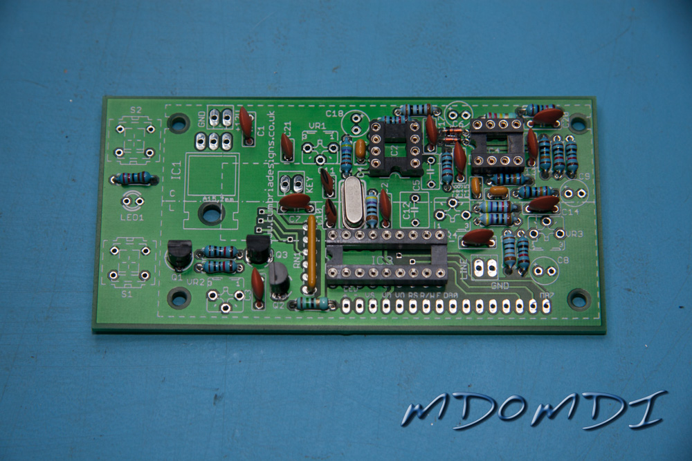
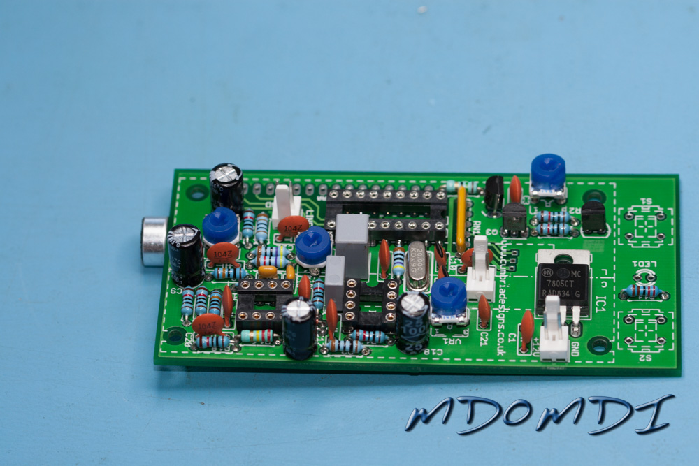
You now need to install the 7805 Voltage Regulator, as with the previous transistors, this component needs to be installed the correct way round, thankfully because it needs to be laid flat onto the PCB this is easy to work out.
I would suggest bending the legs first with your long-nosed pliers before the component is fitted into the holes on the PCB, this does require you to hold the component roughly in place so that you can work out where to bend the legs, only bend one leg at a time, it is easier to do this!
Once you have pushed the pins into the PCB, make sure that the hole in the heat-sink of the Voltage Regulator lines up with the hole in the PCB and then tack a single leg into place, this will allow you to do any slight adjustment that may be required.
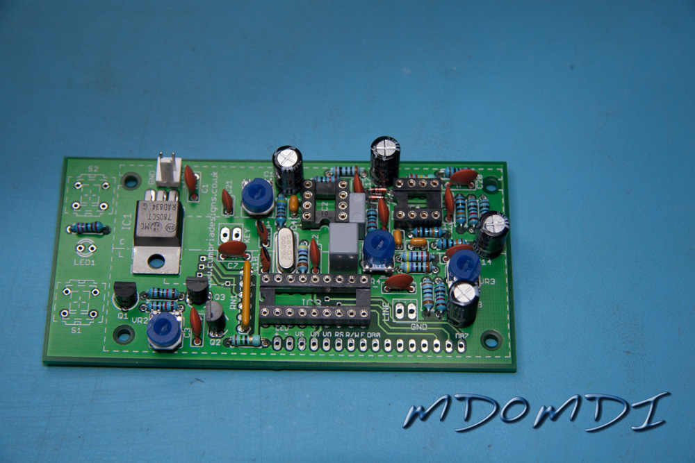
Install the Variable Resistor’s.
These need to be installed the correct way, luckily they can only fit one way round, these will push into the PCB and then lock into place which makes soldering very easy.
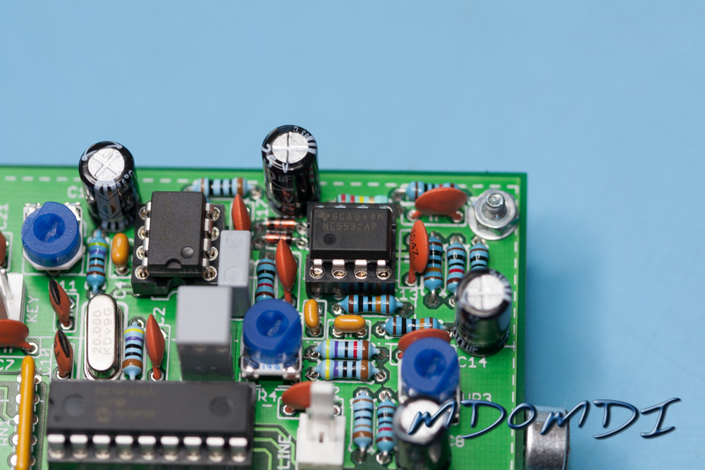
Now installed the Electrolytic Capacitors.
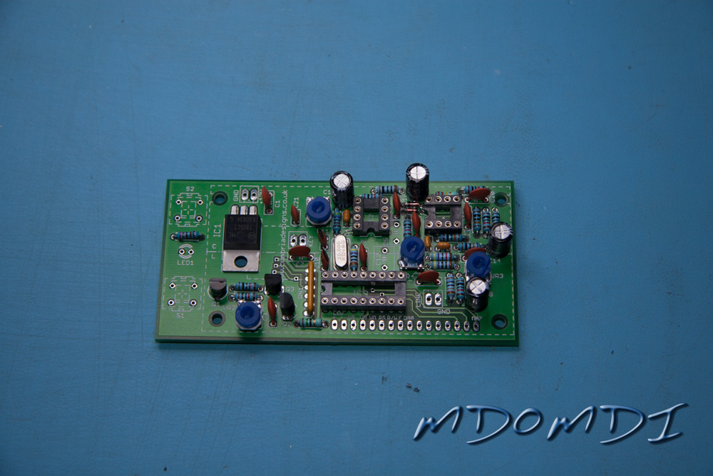
These need to be installed the right way round, thankfully these are normally labelled very clearly, with either a light or dark line running down the length of the capacitor which indicates the minus ‘-‘ leg.
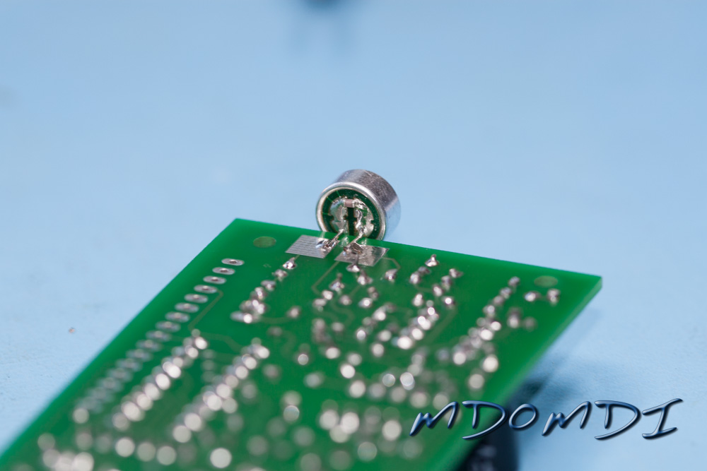
Now install the two Polystyrene Capacitors, these can be fitted either way round and are usually very easy to distinguish which is which.
Although there is no right way or wrong way to install these, it is advised to install them so that the locking plate on the back of them faces the centre of the board.
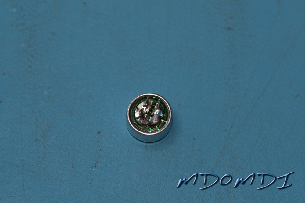
This is the only issue that I really had with this kit. In the instruction is has a small drawing (shown below) which should enable you to work out which pin is which!
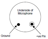
But, as you will see from my photo below, the underside of the microphone supplied does not have these features and therefore you cannot readily see which way round it needs to be installed.
If you have this problem as well, then just check the resistance using your Digital Multimeter between each leg and the case of the microphone in turn, one of the legs should be a complete short, and the other will have some resistance, the leg with the short is the ‘Ground’.
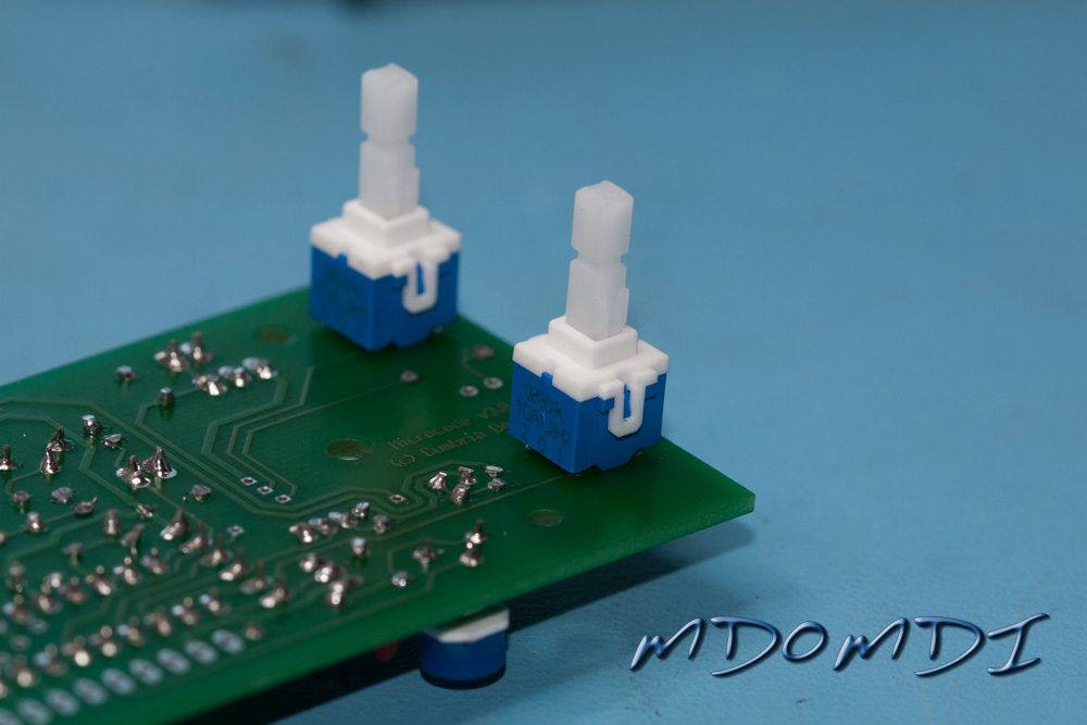
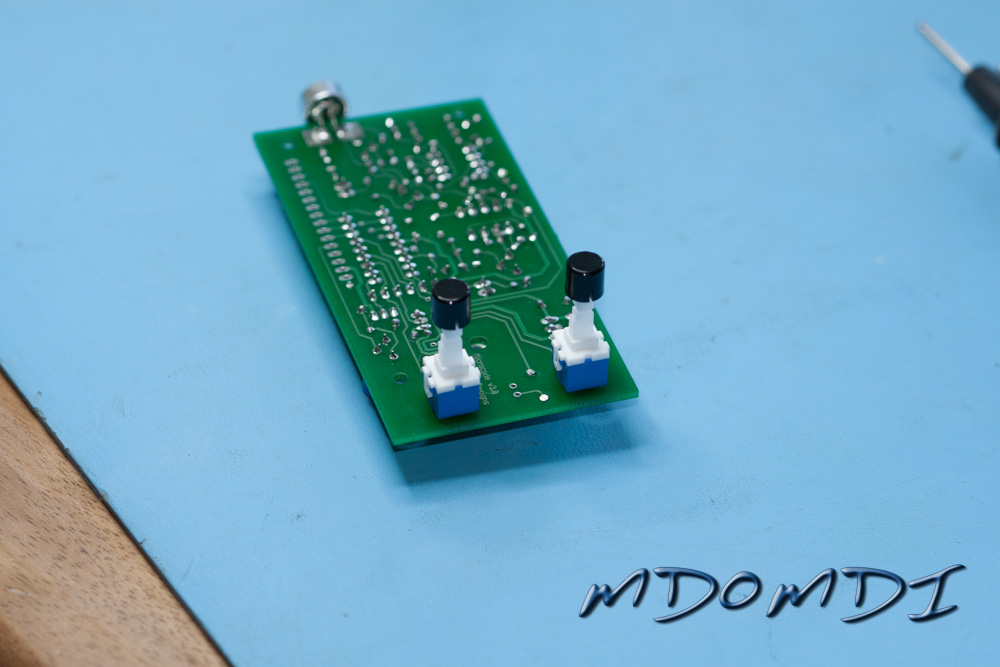
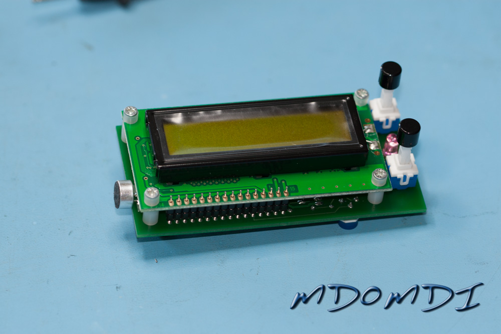
As you did with the transistors earlier, just solder one leg inn place first, this will enable you to make sure that the switch is sitting flat on top of the PCB properly before you solder in the remaining legs.
The Black plastic caps should push onto the top of the switches quite easily, there is no need to glue them into place.
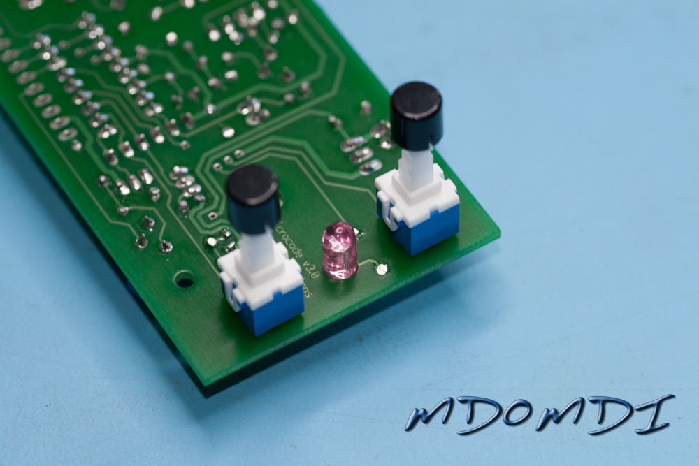
I have installed mine down flat onto the PCB, but you are advised to solder the LED above the board so that if you mount it into a small case it will be at the same height as the switches.
I have other plans for this kit so for the moment have soldered the LED down at the level of the PCB.
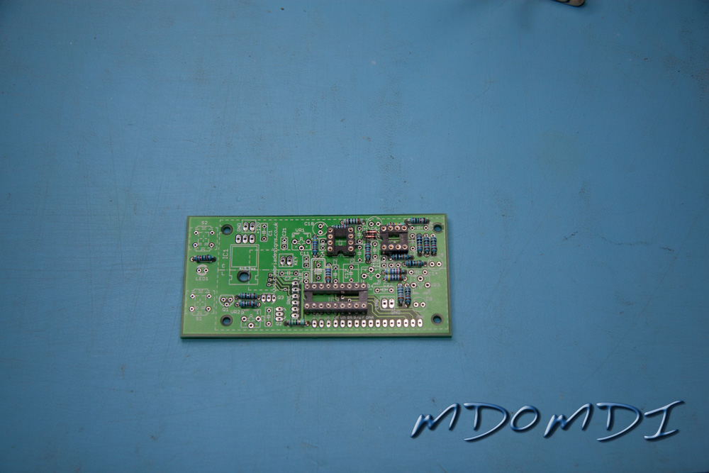
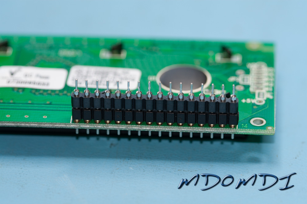
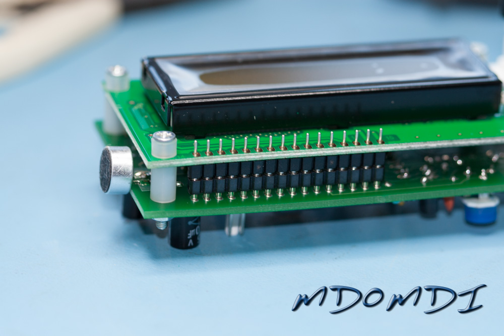
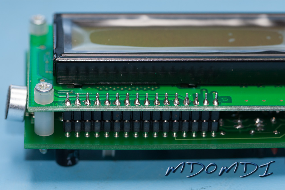
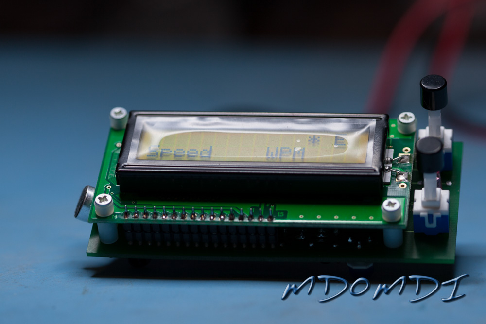
Now you get to play with the most recognisable part of this kit, the LCD Module.
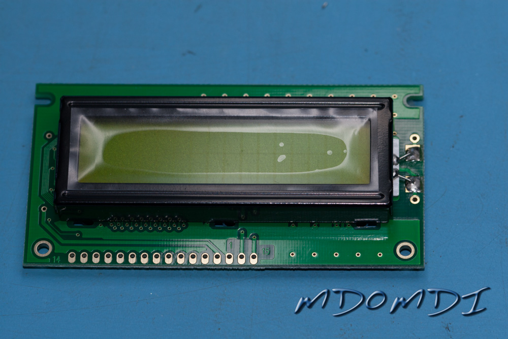
The installation of this part is a little fiddly but should not cause you any problems, just take your time and don’t rush it.
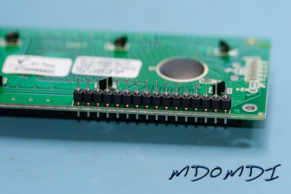
You will need to turn the unit upside down and fit the 16-way SIL strip into the holes on the back of the LCD Module. DO NOT Solder it into place yet!
Then plug into this the other part that you have, this should be the 16-way SIL Socket.
Install IC2 into its socket, make sure that you have first discharged yourself, and also making sure that the component is installed the right way round! The Microcode Morse Code Reader is actually looking great and nearly done.
Testing the Microcode Morse Code Reader
With all of the components finally fitted you will need to get ready to connect the finished kit up to a suitable 12V supply.
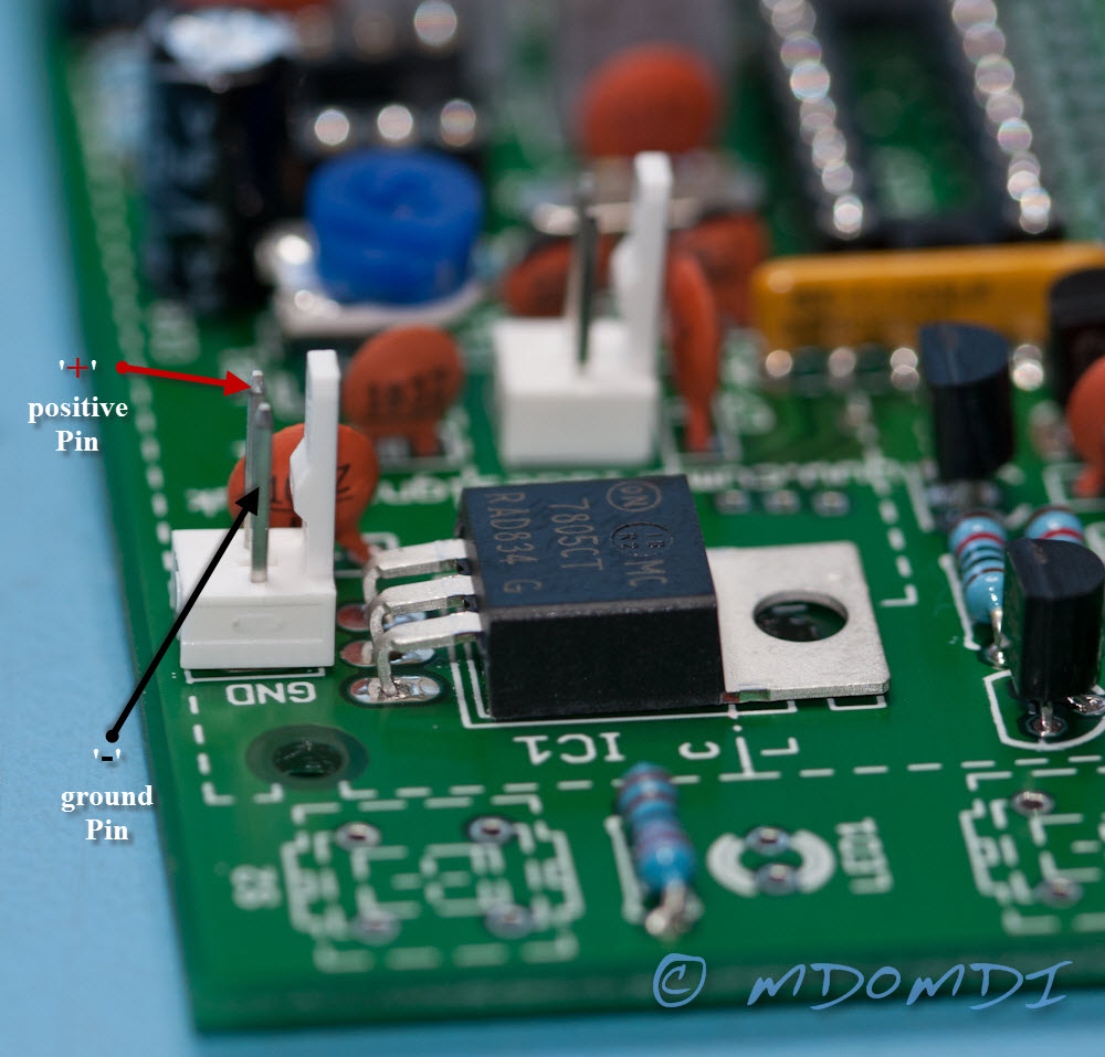
With a Digital Multimeter set to resistance, place the red lead on the ‘positive’ (+) connection to the PCB, then place the black lead to the ‘ground’ (-) connection to the PCB, these are displayed below, but are also very clearly marked in both the instruction manual and also on the silk-screen on the PCB itself. You should get quite a high resistance value.
The next test is again straight forward, but for the users that are new to electronics and kit building some information has been left out of the manual, though it is quite easy to work this out.
You are asked to check the resistance of the +5 Volt Rail, to achieve this we need to check the resistance again between the ground and the positive output from IC1, to do this we need to know what pin of IC1 is the output?
This is actually very easy to work out, even if you are not that knowledgeable with the 7805 Voltage regulator. At the start of this page where I list the parts, you will see that I have attached the ‘datasheets’ for the major components, and here you will see the datasheet for the 7805 Voltage Regulator (to save you scrolling up click the link below to view it).
Datasheets will always displays the pin outs of a device, below you will see the required information.
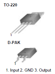
You are making sure that the resistance between the output and ground is not a dead short.
If all is OK you are ready to connect the device up to the 12V supply in your shack.
Follow the ‘Powering Up instruction in the manual (5.1.3) and you hopefully should end up with a very useful and working Microcode Morse Code Reader.
Conclusions
I am very impressed with the Microcode Morse Code Reader kit, from the very well laid out website, stuffed with useful information and other great kits as well, to the entire process of ordering the kit online which was very simple indeed, and the quick dispatch, it was received very quickly even though it was ordered over the Christmas period.
The Parts themselves are well packaged and thought has been put into the packaging of the components to aid identification for those new to electronics and also to ensure that no damage comes to any of the static sensitive devices.
The manual as manuals go are well above some of the rest, unlike most of the other kits available out there, this manual is very thorough and aimed at the new hobby builder with either little of no knowledge of electronics at all. That said it did have a few small omissions which I hope that I have helped with above, but even these could be found out themselves with a little common sense and/or a web browser and the internet. All of the images in the manual are clean and easy to read, and no information vital to the building of this kit is missing.
The User Instruction describing how to use the kit itself once finished are also very easy to follow and understand, nothing has been left out.
Calibration of the unit is a little fiddly, and you either need an Audio Generator, or an HF radio that will transmit at the frequency that is required, the process explained in the manual is not really suitable for the new user and he might get a little lost to what is actually required. I found that the best way to configure the unit is to use a straight key plugged into your own HF set (this is assuming that you already own an HF radio), set the side tone to the desired value, most radios will allow you to set this to what frequency you prefer, for this example I will say 750Hz, and then with the volume turned up on the radio, hold the key down, and you should hopefully hear a constant side tone at the frequency that you prefer and then adjust VR1 till the Red LED lights up, turn it a small way each side of the lit LED so that you can gauge the centre position, once this has been dome you should have a good starting point.
The use of the unit is actually very good, it beats the MFJ device by miles, and although not as good as the human ear, it will enable some that likes more but cannot copy it to be able to copy most QSO’s to say 85-90%, you might even get better than that, but don’t expect it to be all perfect, that has to be left to your own ears and time!
My own views…
Is it worth the money? Hell yes!
As a small kit, I doubt you will find anything as good anywhere else, for say the Intermediate Course, this kit is perfect, there are no real issues with the PCB itself and although I did find a few of the solder pads a little on the small side, I have seen worse and as long as you take your time you should not have any problems with the kit.
Would I recommend the Microcode Morse Code Reader kit?
Yes, 100%.
Communications with the Supplier?
This was the only issue that I had with this kit. When building it I did telephone Cumbria Designs for help with regards to the polarity of the Microphone, this went to an answerphone and I never got a reply. Although I managed to sort this problem out in the end, it is a little worrying that I did not receive a telephone call back. This said, I do not think that this is too much of an issue, some of the more well-known larger kits out there do not offer you any contact at all with the manufacturer.
Is this suitable for new users?
Totally, 100%, A very easy kit to build, so long as you have a little common sense, and can follow we-written instruction then you will have no issues with this at all.
I hope that you found my review of this kit helpful, and all the best in building your own version.