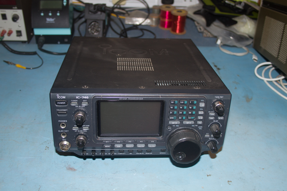
Some time back I was given an Icom IC-746 Transceiver that someone did not want any more, the radio itself is a really great little set, it comes with the same screen layout as the IC-706 and like that radio it have 100 Watts on 2 Meters in all modes, so it is quite a nice and versatile radio, but all that said it had one small and minor problem! The CAT Control socket on the back of the radio would not hold onto the lead when it was connected, and as you will see, it had a not so clean repair done to it at some point, so as I had some spare time I thought that I would go about repairing this problem, after all, it should be cheap!
Icom IC-746
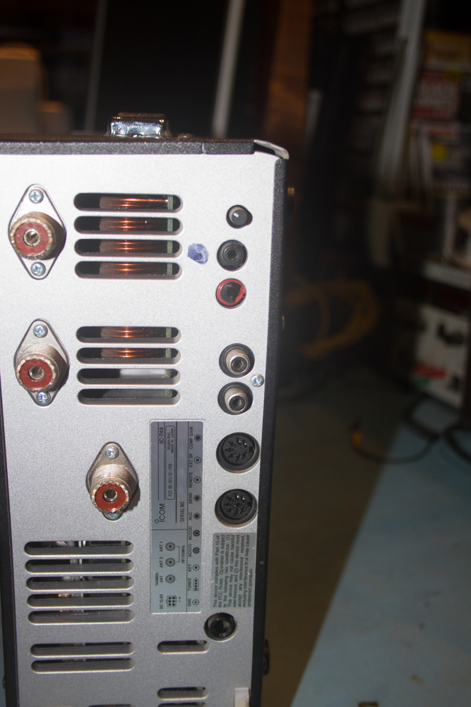
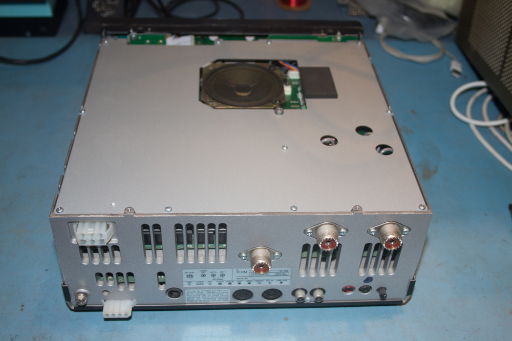
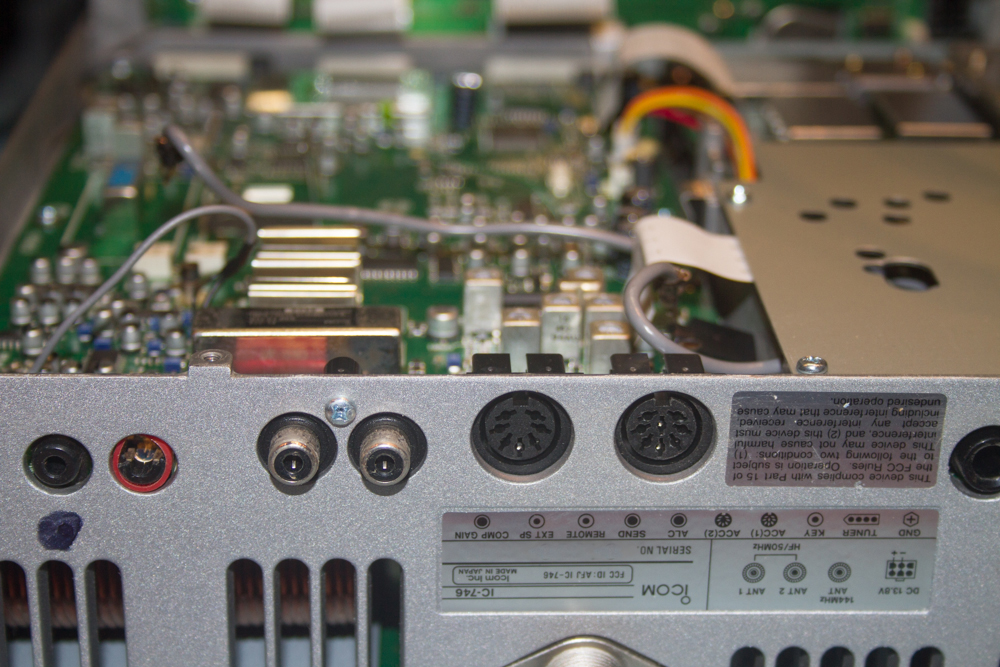
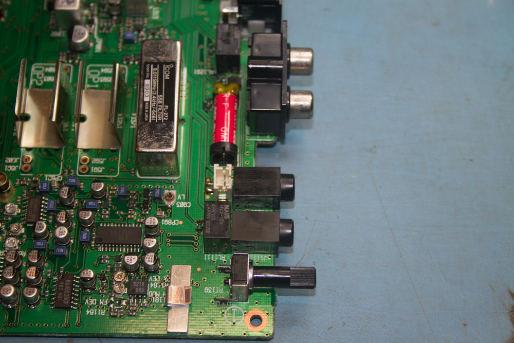
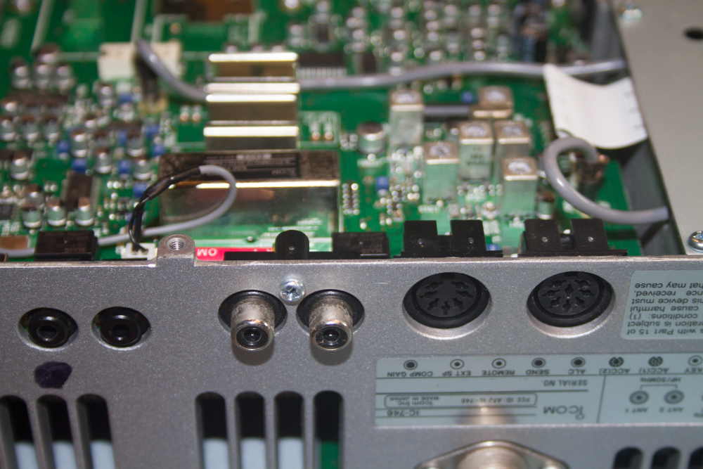
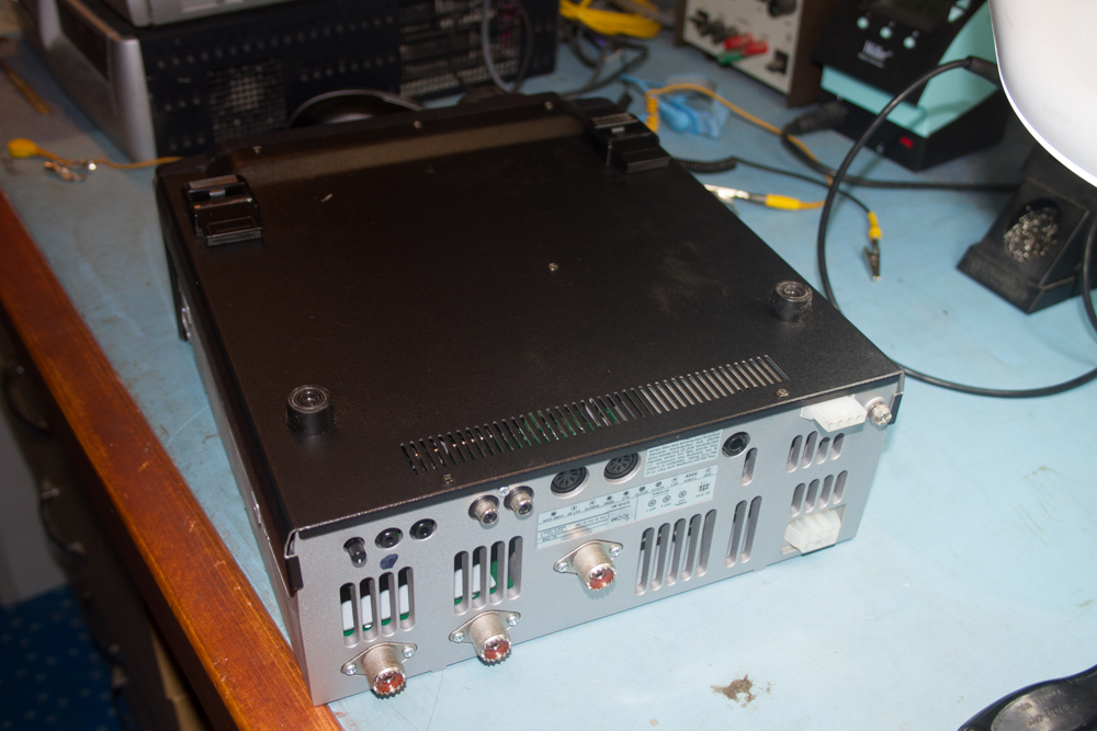
As you will see from the image below, the CAT Control Socket (the one that looks red), not only looks wrong, but we can see from the image that it is broken.
Icom IC-746 Rear Panel
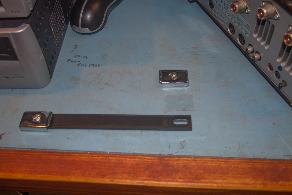
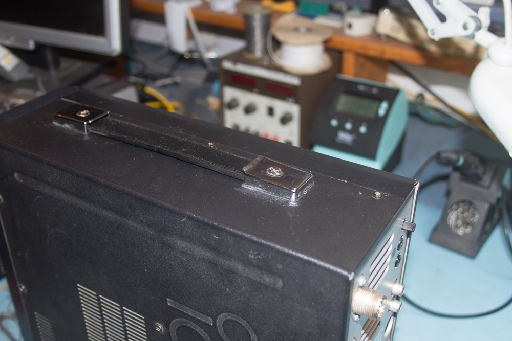
First thing that we need to do is to remove the handle from the unit, this is simple, just remove the two screws and remember to keep track of the plastic squares that are underneath the handles, these protect the case from additional wear that can occur when the unit is being carried by the handle.
Icom IC-746 Removed Carrying Handle
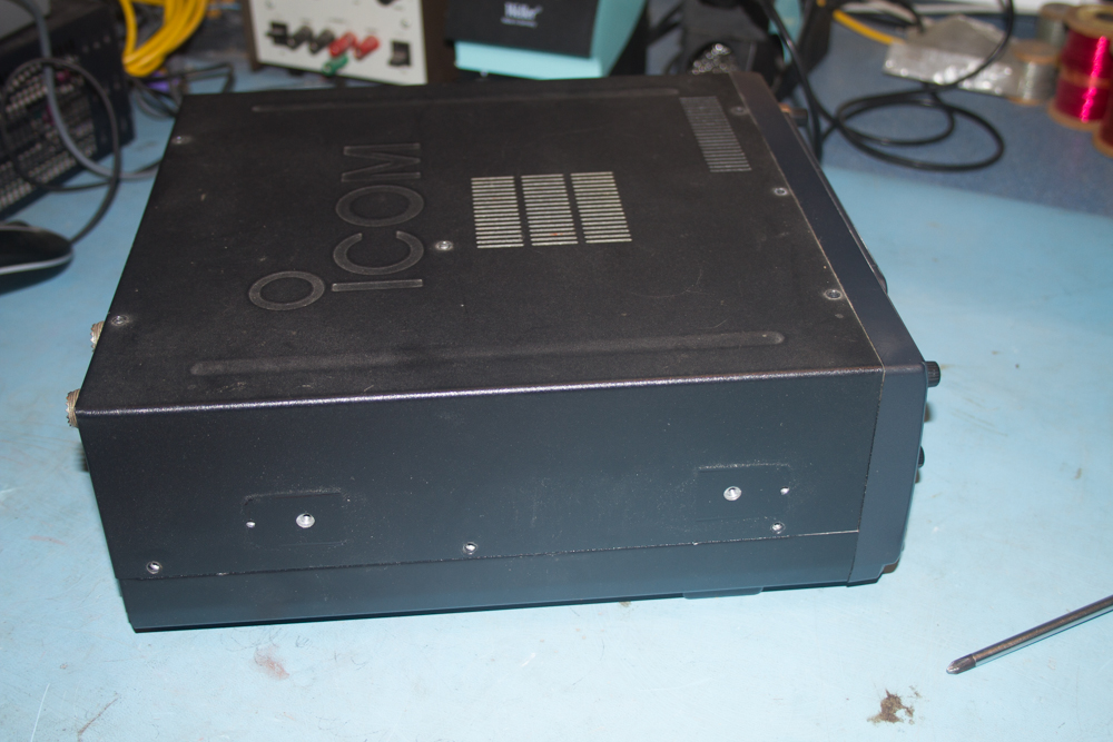
Icom IC-746 Outer Case
First remove the top section and then place this somewhere safe to stop it from getting marked or damaged.
Icom IC-746 with Outer Case removed
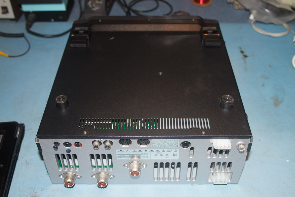
Now turn the unit over and remove the other case.
Icom IC-746 bottom case
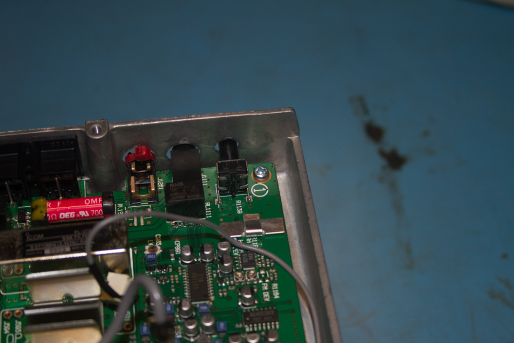
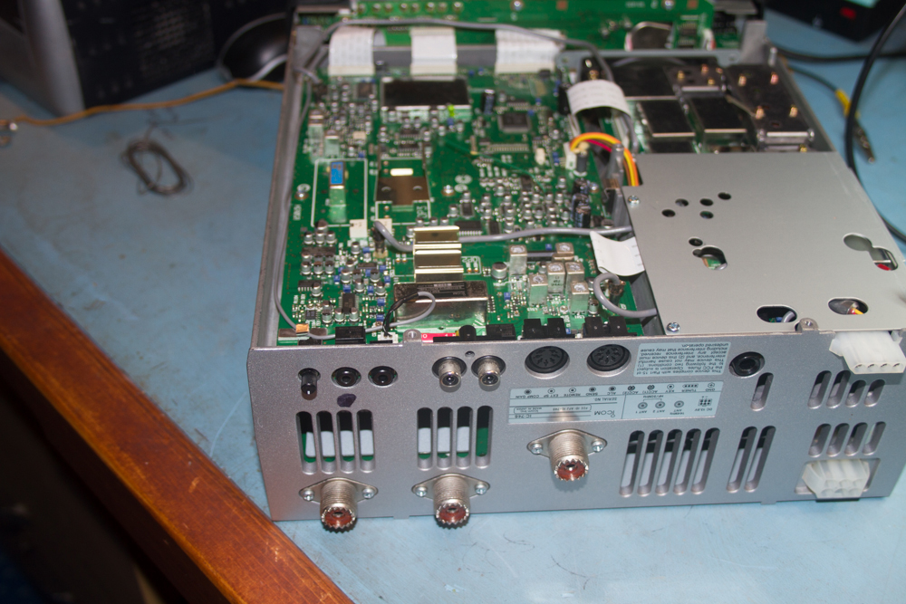
We now need to look at the board at the rear of the radio to see what the socket looks like.
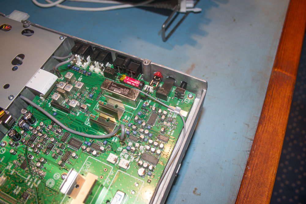
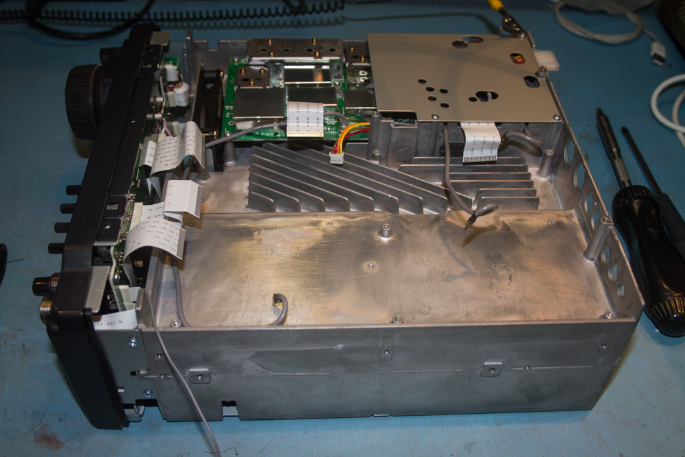
Icom IC-746 with covers removed
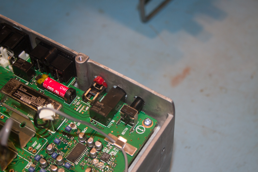
Looking at the rear of the radio we can see that the make shift repair made by someone was to use a red colour cable tie around the plastic of the socket to hold it together, although this obviously had worked for some time, there now seems to be some of the plastic from the socket missing, though at this time I am not sure where it is as it has not fallen out yet!
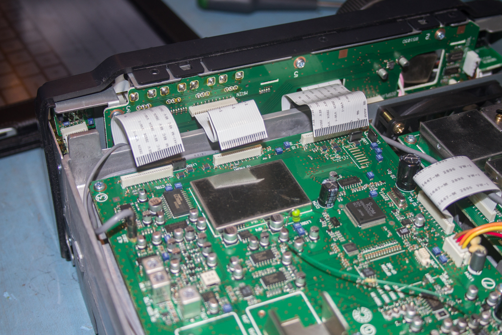
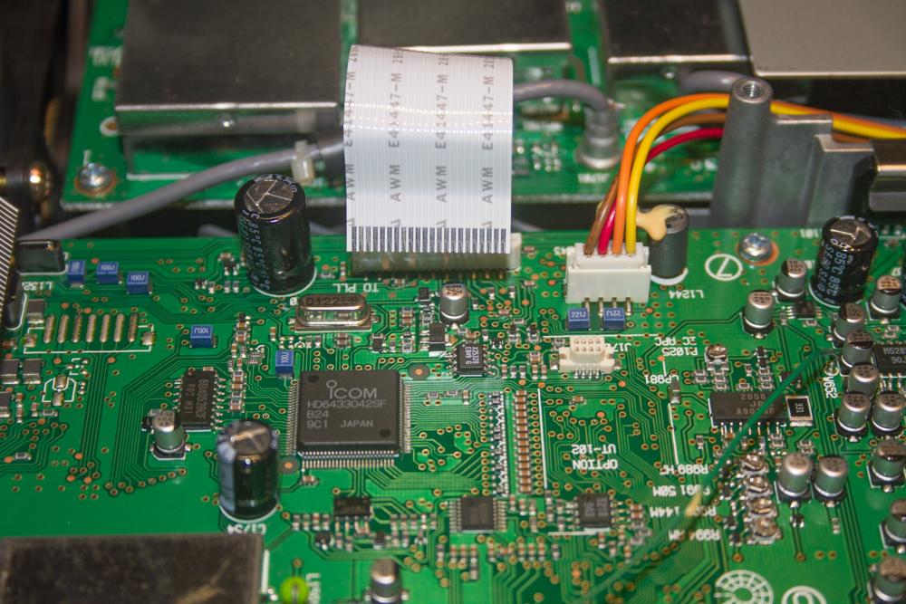
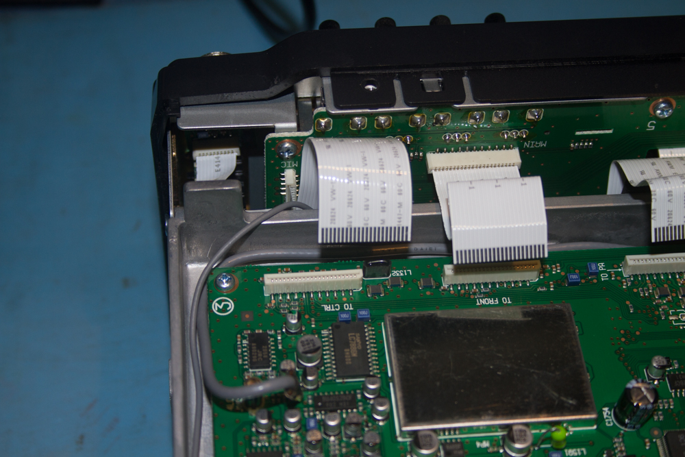
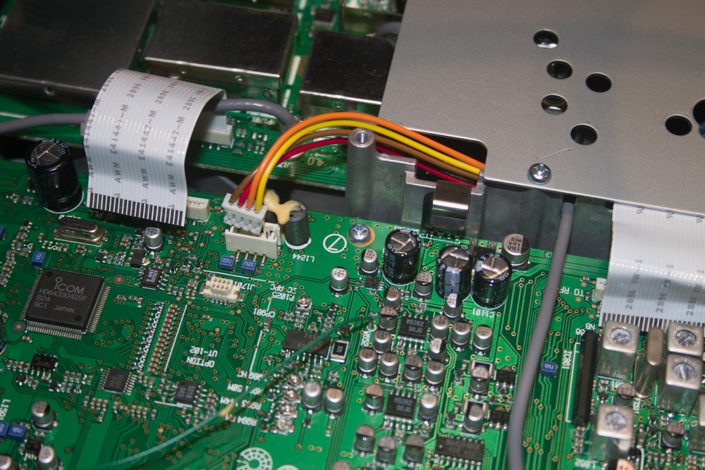
The problem here is this. We need to be able to un-solder the present socket from the underside of this PCB, this means that we have no choice but to remove the PCB from the radio, now if you are unsure about this then STOP here and basically work backwards and then either pass the radio to someone who is happy with taking a radio apart, or of course send this to Icom for repair. That said, the task is not that difficult and as long as you take your time it will end up saving you about 2 hours labor charges and the cost of the replacement sock, and when you take the cost of shipping into account this could come to over £100 easily. [dt_gap height=”10″ /] So if you are happy to follow my lead here then you should not run into any difficulties. The first job it to start disconnecting the connections to this PCB from other sources on other boards in the radio. Start by removing the 3 flat ribbon cables that are at the front of the radio, these will just pull out, but be careful not to twist or rip these cables or you will be waiting many weeks for replacements to arrive. Also do not use pliers or anything that grips the flat ribbon cables, just use your hands, and as per normal, be aware of static!
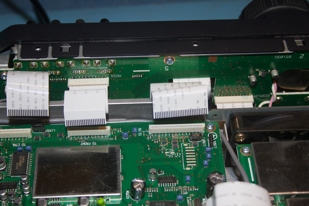
Now do the same to the single flat ribbon cable that is labelled ‘To PLL’, again this just pulls out from the socket.
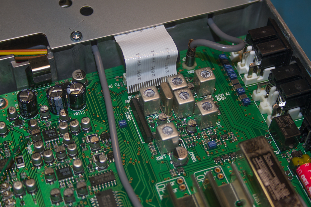
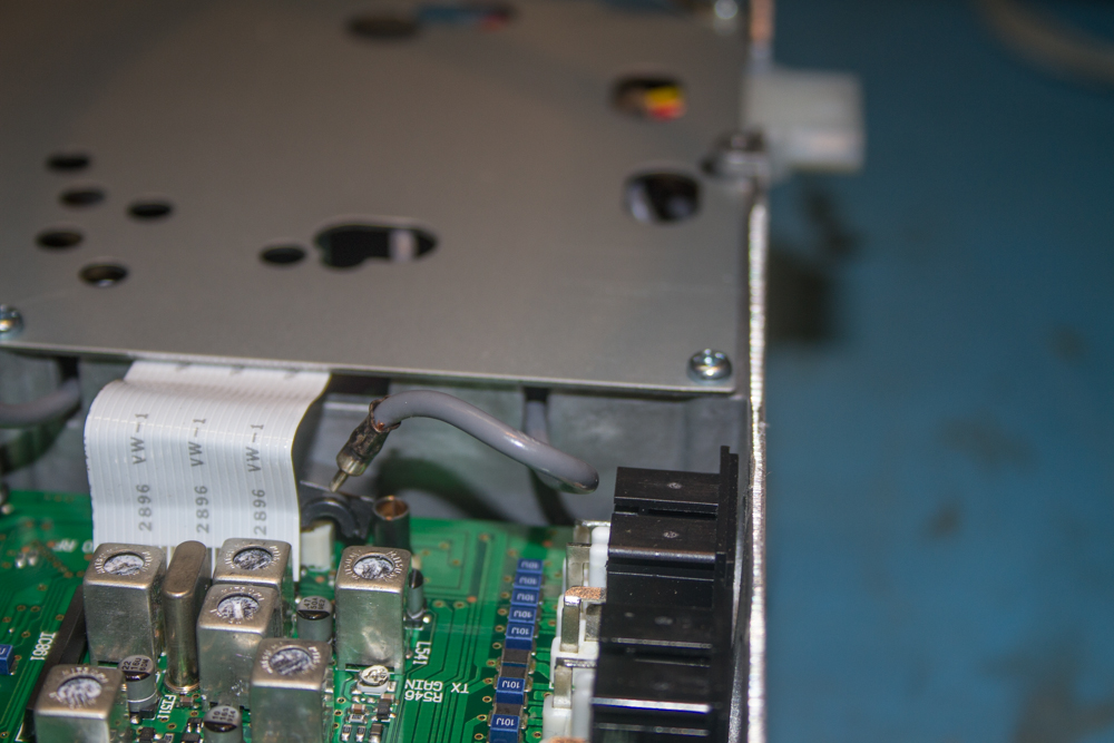
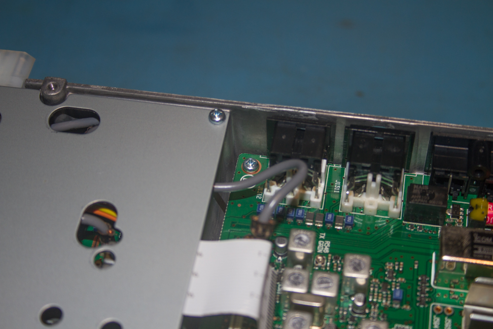
The next to remove is the one labelled ‘To RF’ that seems to disappear under the shielding as shown in the image below.
Now we need to remove the small coaxial connections to the main board, start with this one, they should pull out quite easily and if not, just give them a slight twist and this should help loosen them off a little.
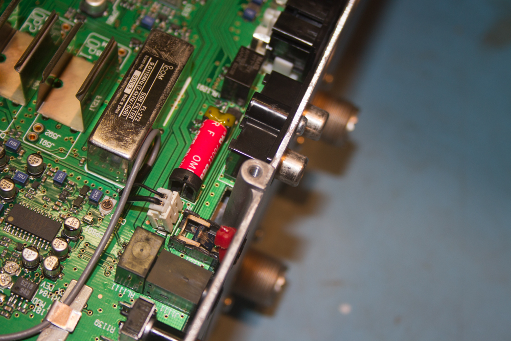
The next one is the one that sits next to the Filter Units.
Now remove the one near the RF section at the rear of the radio.
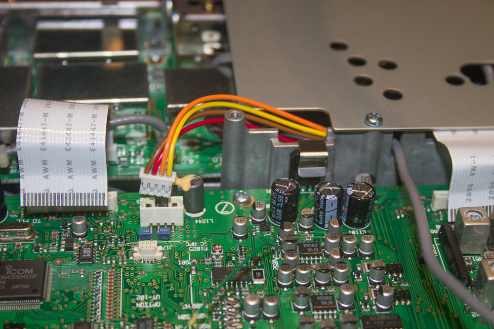
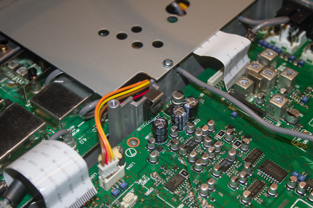
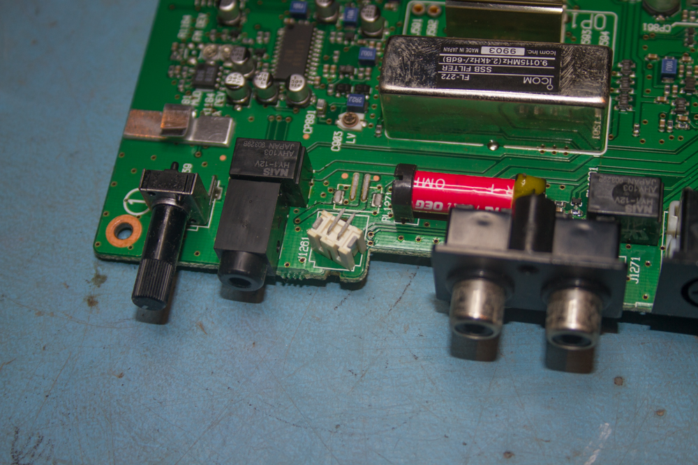
The next connection to remove is fairly easy to locate, it has some bright leads connected to it and will be fairly firmly connected, but applying a little force will see it come apart. A point to be aware of here is that it will only go back into the socket the correct way round, so you should not have a problem when you reassemble the unit.
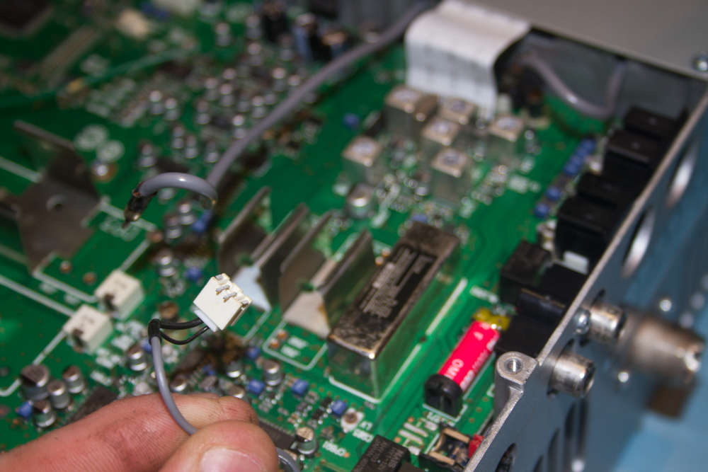
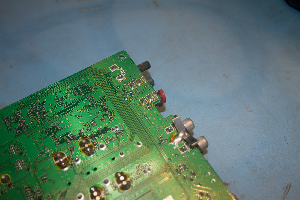
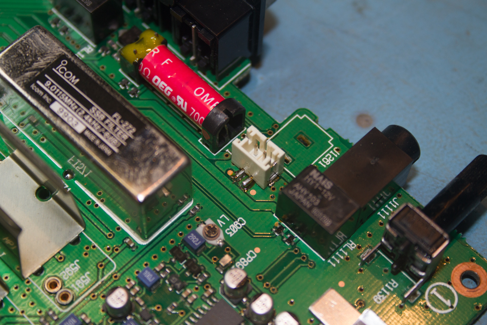
Now I had a slight hic cup with the next connection and hopefully anyone following this will not have this problem occur, but I noticed that the connection to the PCB was not sitting as flat to the PCB as it should, and sure enough, when I tried to remove the connection the entire socket came off – Opps!
I can only assume that this would have happened when the prior repair was undertaken, if this does happen to you don’t worry too much, as long as there is no damage to the PCB then it is easily repairable.
Looking back at the PCB where the socket was removed from, it looks to have been a very clean break, and this will be very easy to sort out. We will do this once the PCB has been removed from the radio.
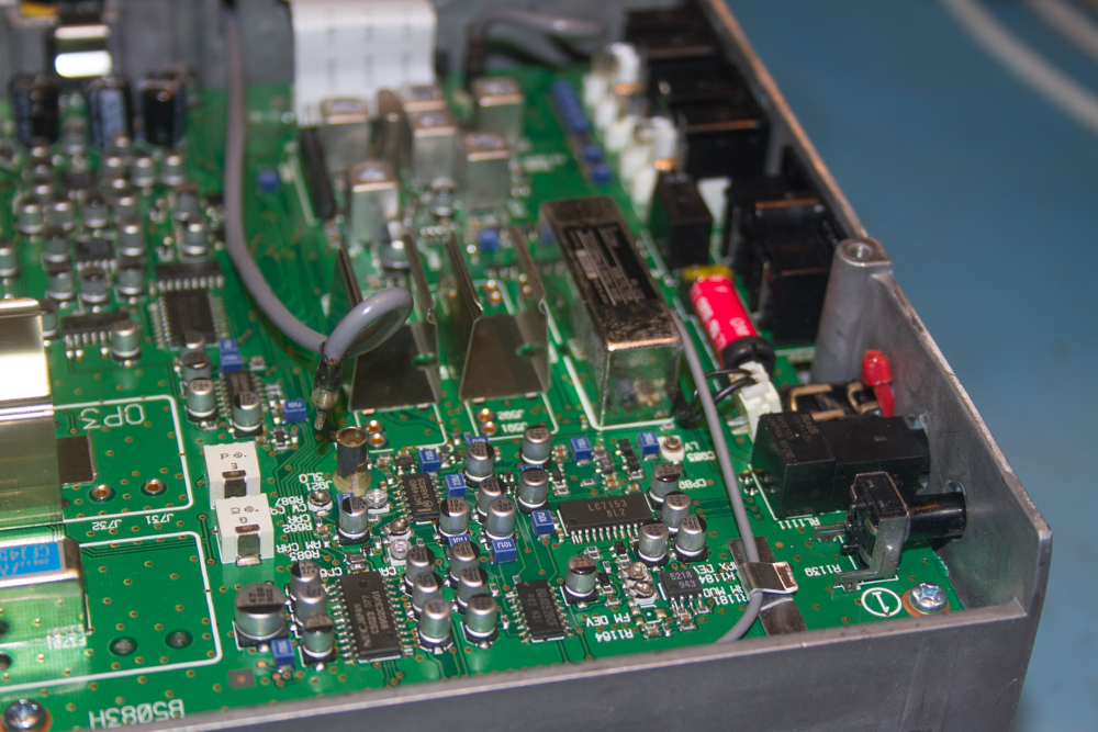
Now onto the hardware, first we need to remove the screw from the rear of the radio that holds the 2 phono connections to the rear of the radio that are used for ‘ALC and SEND’. Make sure that you keep this somewhere safe.
Remove this screw first, you will find it to the front of the radio and should have a large number ‘3’ labelled next to it.
The next screw to be removed it at the opposite corner to the front of the radio.
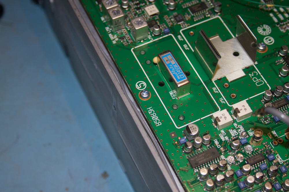
Now remove the one next to the filters, this should be labelled ‘5’.
The next is the other side of the filter units and is labelled ‘6’.
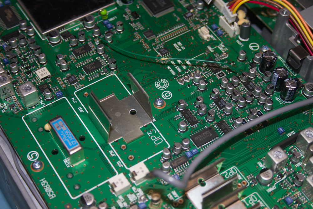
Now look over the other side of the board near to the RF Shielding, this one is labelled ‘7’.
Now look to the rear of the radio, next to the RF Shielding.
Now look to the rear of the radio, at the other corner of the radio, this one is labelled ‘1’
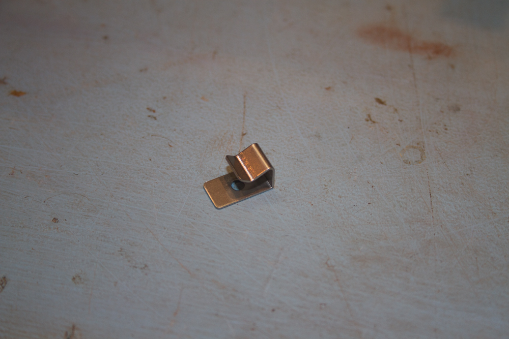
Now for something a little different, if you look over to where the RF Shielding is, you will notice a transistor up against the aluminum of the radio, it has a small clip that acts as a small heat-sink for the transistor and also locks it in place. This needs to be removed so that the board can be removed.
The clip will simply pull off the transistor, try to make sure that you pull it directly up from the radio.
Now the board is totally free of the radio, very carefully start to pull it away from the radio, trying to remove each lead that is in the way one at a time. Make sure that you do not break any cables or even pull them off other boards by being heavy handed, take care as you could damage the radio here!
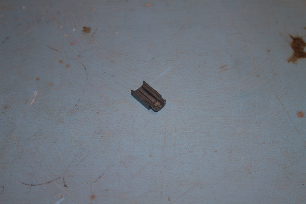
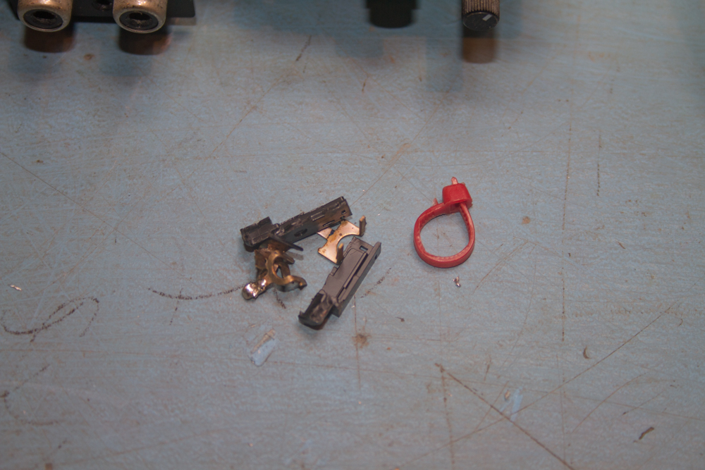
Sitting underneath this board was the missing plastic from the socket…
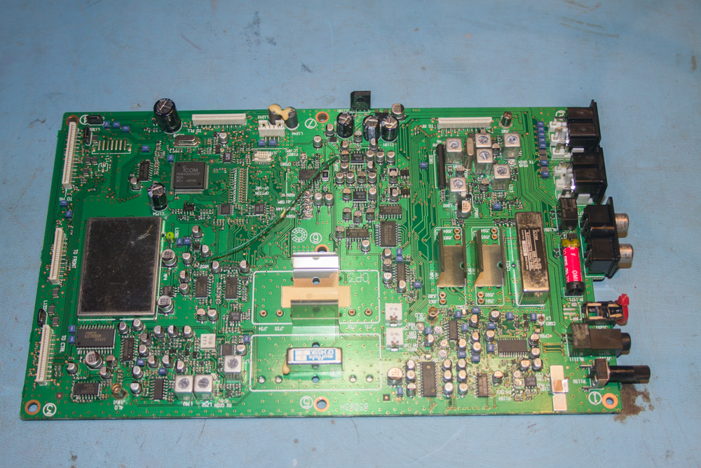
Here is the board that we have just removed. Again make sure that when you put it down it is somewhere safe, in my case I am using antistatic mats that have multiple earth links to isolated earthing points that are not attached to main earths. It is always best to be on the over cautious.
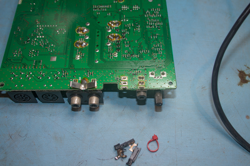
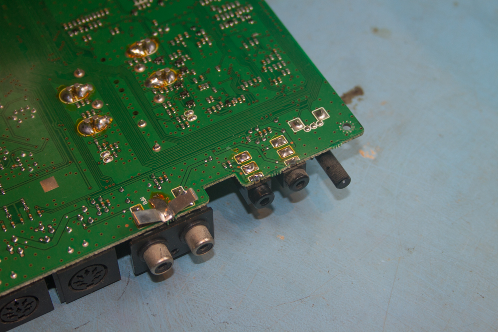
Turn the board over by just holding onto the edges of the PCB to keep any static to a minimum so that we can view the solder side of our damaged socket.
Using a good soldering iron and a solder sucker, remove the solder from the rear of the damaged socket, once I have done this, the parts of the socket just fall away from the PCB.
Here is what is left of the socket….
Now is a good time to replace the socket that pulled off the mainboard a little too easy.
I had two options here, the first and original method is to use solder paste, applying this to the PCB and then just place the socket in place and applying a little heat with my hot air soldering station and this will adhere the socket to the PCB, or use normal lead solder to sort this out.
I decided on the latter method as it is often the stronger method as long as the soldering is neat enough. I started off turning the iron down low and tinning the areas on the PCB where the socket had once sat, one this was done, it was just a simple case of lining up the socket to the PCB and applying a little heat to each connection in turn and the socket will be then fixed in place quite neatly and also quite strongly, this should not fall off again…
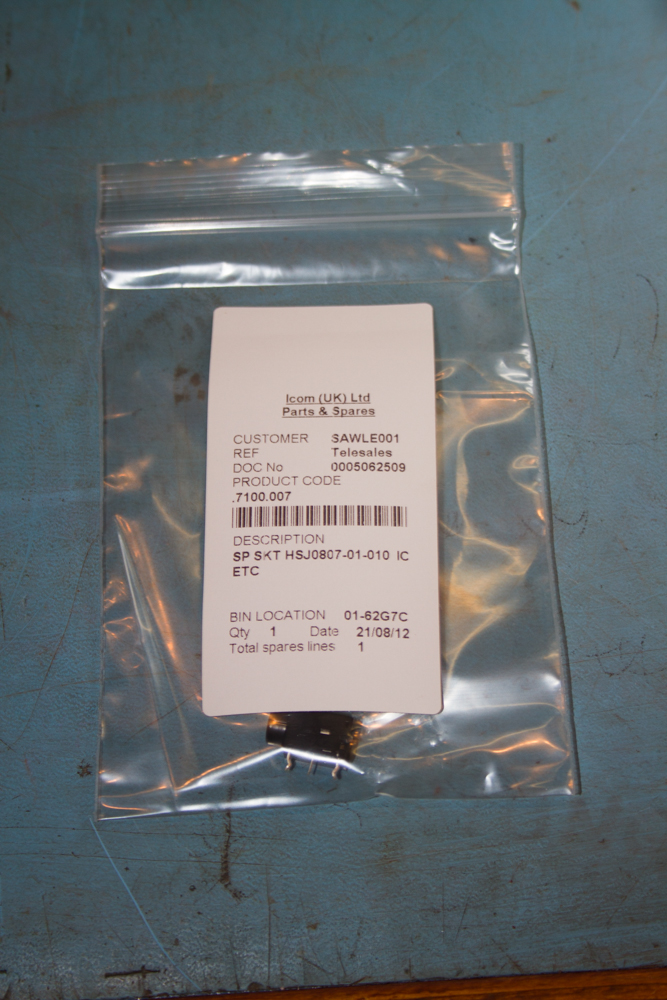
Now for the replacement socket. I could have got this from CPC, but at only £1:60 from Icom direct, I at least know that I would not have a problem getting it to fit, which I might have getting hold of a third party make.
It is just a simple task of placing the socket in place and then turning the board back over to do the soldering, a good tip here is to just slightly push the protruding solder connection apart when the socket has been pushed through the PCB to hold it in place.
Turning the soldering iron back up to its normal working temperature, it is a very simple task to just solder the three connection on the back of the board.
Now we simply have to refit the PCB back into the radio very carefully, making sure that no leads are bent, damaged or trapped in any way, once the board ios fitted back into the radio, spend a little time looking back over the board to make sure that nothing is trapped under the board, spending time here is better than spending more time removing the board again after you spent a while locking it down in the first place.
Once in place and you are happy with it, replace all the screws that you removed starting with the one on the rear panel that holds the ALC and SEND sockets…
With that now done, replace all the other screws first, making sure that you have none left over…
The replace all the leads in the opposite order that they were disconnected, be very careful with the flat ribbon cables, they will go back into the sockets very easily and with little force applied so long as you make sure that the cables are parallel to the socket, take you time and you should have no problems here.
Finally if you are happy, replace the covers of the radio.
Once you have both covers screwed back onto the radio the very last task is to screw on the lifting handle. Just make sure that the plastic squares are placed between the handle and the cover.
Finally we have a complete radio again, just one thing left to do.
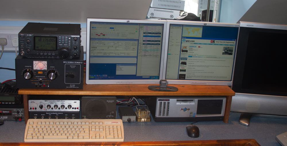
After connecting the radio up to the antenna and the computer we just need to check all is OK, as thankfully nothing scary to worry about, all OK, and spending just over an hour on the workbench has saved me a week or so without a radio and also around £100 in cost to send it off the island and get it repaired by Icom…
I am now retired and living on the Isle of Man, my background is as varied as it gets, ranging from Information Technology to Graphic Designer and 3D VFX Artist, using and teaching Autodesk Maya, Softimage, and Smoke, one of more enjoyable positions. Since Moving to the Isle of Man I try to keep myself to myself and work on the house, I don't do much with regards to Amateur Radio or Electronics anymore, but I am still interested in the hobby and may well get back into it one day....