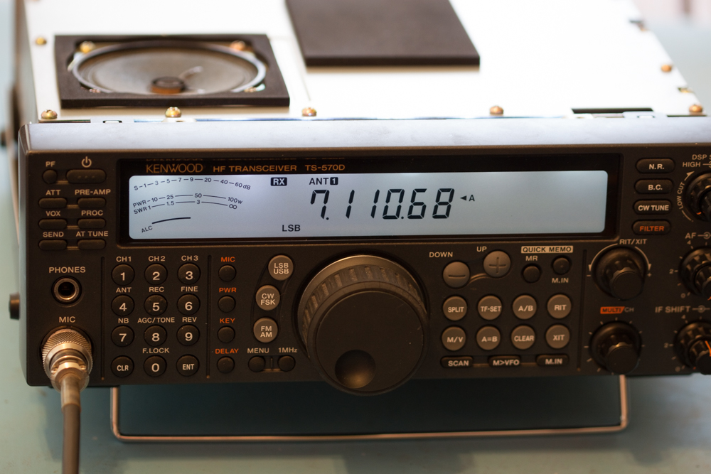
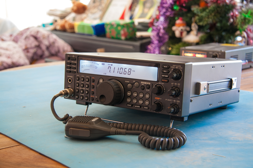
Kenwood TS-570D - Blue Display Modification
One of the reasons for wanting this radio was in fact to do this modification!
I know that sounds a bit weird, but the radio is a great little radio anyway, but being that you can alter the display colour to a much more eye friendly colour is a great little bonus, especially as it involves a soldering iron, though a few small minded people will always say ‘Why did you do that’ and ‘I don’t like the Blue, as Amber is more friendly on the eyes in low light’, well I don’t care what you think, each to their own and what the hell, it’s my radio and I don’t give a toss what anyone else thinks, if they don’t like it then you don’t have to read on…
That said, the finished display mod is very friendly on the eyes indeed, and in low light or even better no lights at all, I found working on the radio all night very easy on the eyes indeed, and I would even go so far as to say that the display is actually a lot easier to read with the blue light and it is certainly a little cleaner with the LCD display being a little more defined as in slightly sharper, though this is a kind of an illusion as nothing has changed but the display colour itself, and this has no effect on the LCD display panel at all, though, that said, it is a lot clearer.
The modification to this Kenwood TS-570D is a little on the drastic side for anyone who regards his radio as another member of the family, and for that reason you may want to give this a miss, that said it is fairly easy, and most of the dismantling actually looks worse than it is, as for the soldering later on, it is all reversible, and if you do get bored of the mod, or want to put the radio back to its original state for selling, then this is also very easy to do, so really no fears either way round.
Now for the sales bit, you can purchase a full kit of parts from ‘HamKit’, I would strongly recommend purchasing the kit from them; they have a very prompt service and will always answer any of your e-mails if you run into problems.
As stated in the original HamKitt manual, and all other modifications around, this will void your warranty, and although it does not have any effect on the radios performance itself, it does mean that you have to dismantle the radio somewhat and therefore if you are a bit heavy handed you might damage something that you didn’t mean to, so please be careful.
Tools Required
Phillips screwdrivers
Small watchmakers flat bladed screwdriver
Small side cutters
Pliers
Small long-nosed pliers
Solderwick and/or Solder Sucker
1.5mm Allen key
7/16” or 11mm Socket
Small Container to collect parts in.
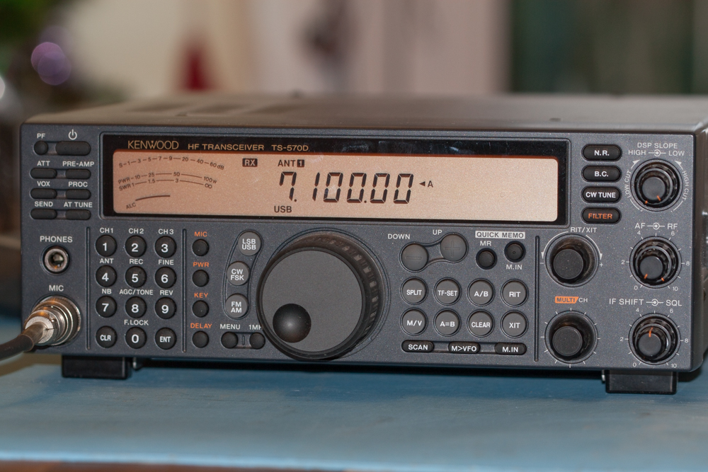
First job is to disconnect the Kenwood TS-570D from the power supply and remove all of the connections to the radio.
Make sure that you work area is very clear and you have enough space to work, if you don’t you could end up losing bits at a later stage.
Also make sure that you put the radio on an anti-static surface, one to protect the radio from harmful discharge and also to make sure than the main display does not get scratched at a later time.
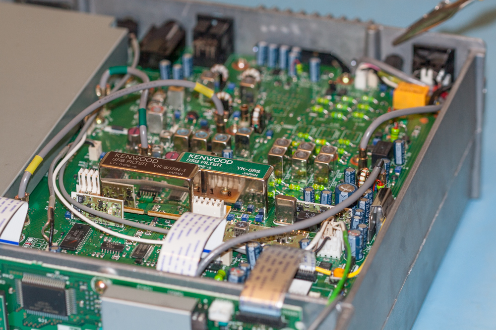
Remove all of the screws that hold the top and bottom covers of the radio in place and then remove each cover and store in a safe place so that they will not get scratched.
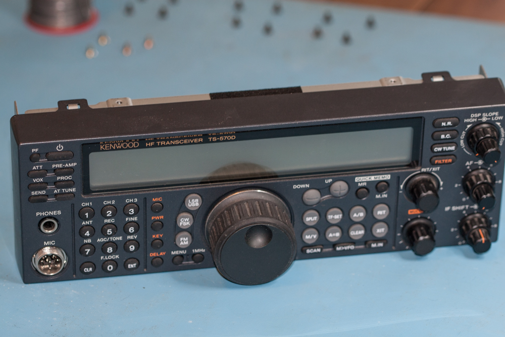
With the covers of the Kenwood TS-570D removed, unscrew the main display from the main body, this is done by unscrewing the mall gold screws from the brackets that holds the front display to the main body of the radio.
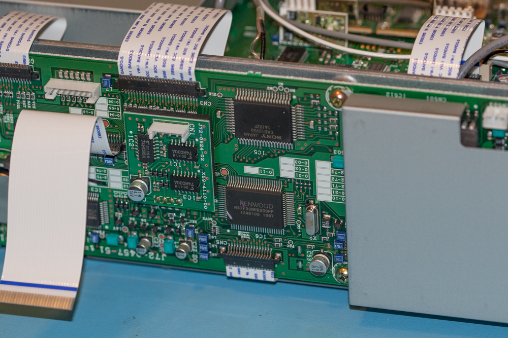
You will have already found that you will have to disconnect a couple of connections to separate the front panel unit from the main body of the radio.
The Item marked by a red box is R41, this is the resistor that you will be interested in if you are thinking of expanded the TX range of the TS-570D.
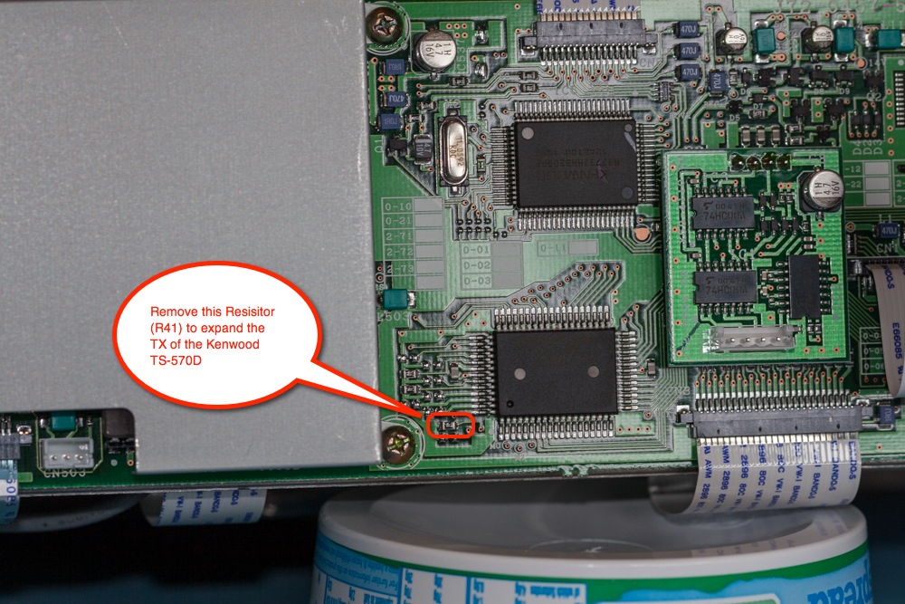
Although not the main reason for working on this radio, I decided that whilst the radio would be in bits I would expand the TX range of the set, the main reason for this was so that I could transmit about 7.100 MHz which this version would not.
The Modification requires the removal of ‘R41’ which is a small surface mounted resistor that is shown below.
When removing this, make sure that you are using a fine tipped soldering iron that has the heat turned as low as possible to save doing any damage to the radio. Just remove the solder from one end of the resistor using a solder sucker and then gently lift the end that you have cleaned just enough to make sure that it will not re-apply itself, with this done, de-solder the other end of the resistor and you should see hopefully fall off, just make sure that you find it just in case it stays inside the radio when the covers are replaced, this may cause some major damage later on… ‘
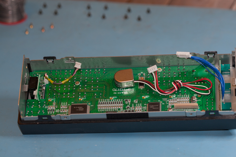
Very carefully unplug all of the cables from the main unit, be careful not to pull on the connection to much as you might end up damaging the cables or the connection blocks that they connect to, but that said this is fairly straight forward.
All of the connections are different so you should not have too many problems putting them back into place.
With the display unit now separated from the main body, you can put the main body of the radio in a safe place.
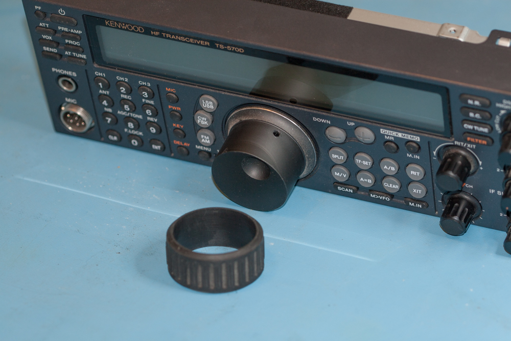
Carefully pull off the rubber ring from the VFO knob of the Kenwood TS-570D; this should be able to be remove very easily, once off place somewhere safe.
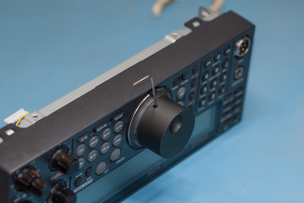
Now we need to remove the VFO knob itself, this is done using a 1.5mm Allen key in the hole in the knob, mine was a bit of a pig and very tight indeed, but with a slight persuasion it should not pose to much of a problem to remove.
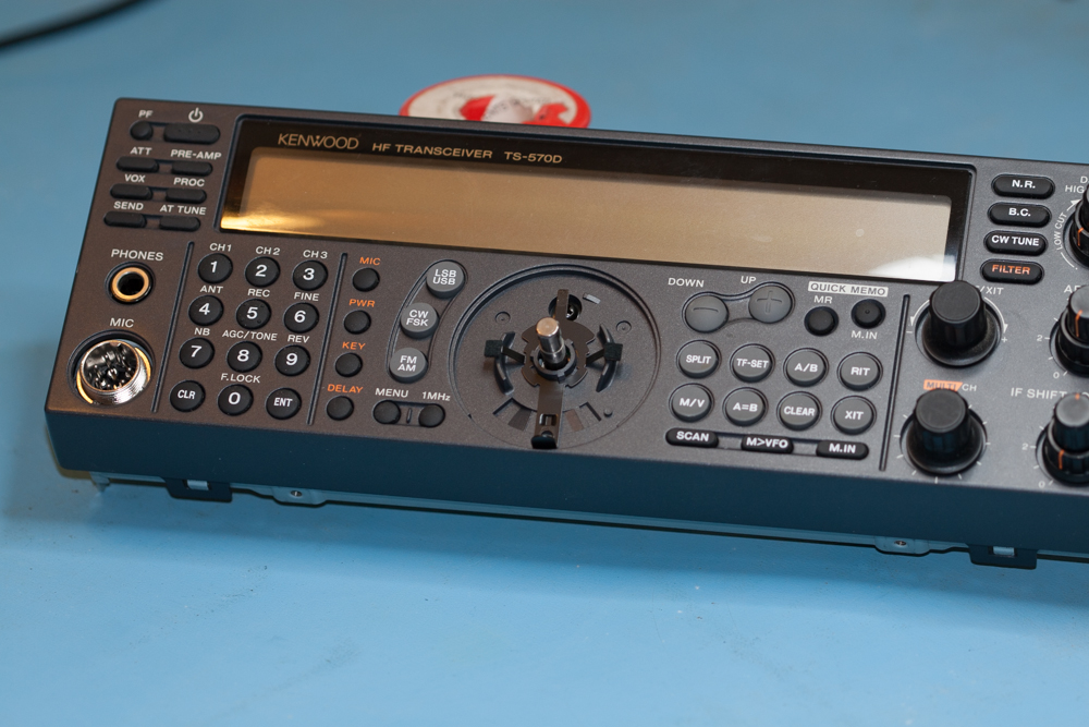
You will notice the metal plate that is now visible once the VFO knob has been removed.
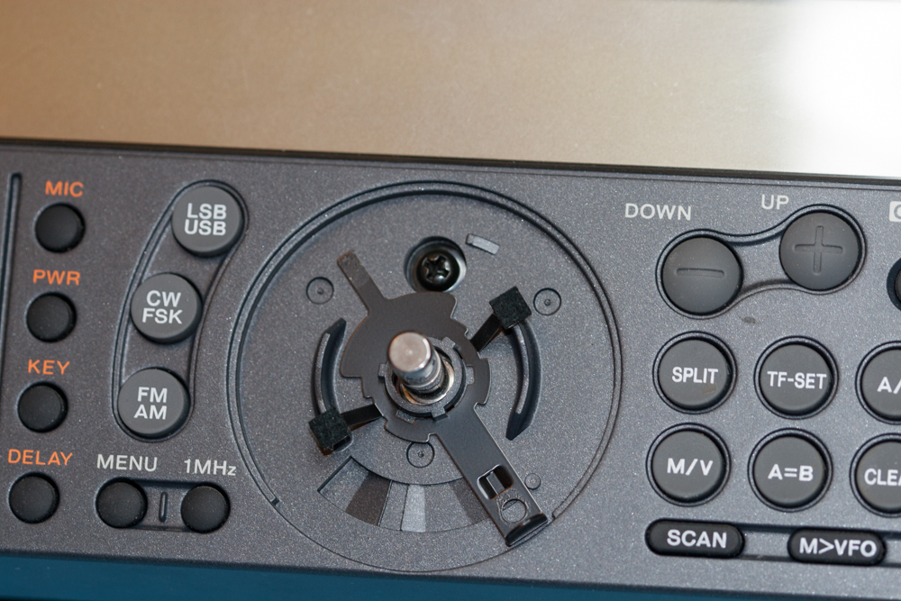
Now twist the metal plate to the left so as to gain access to the screw that was hidden behind it.
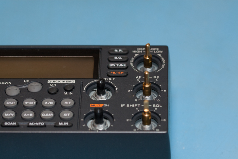
Remove the five knobs from right hand side of the display of the Kenwood TS-570D and store them safely.
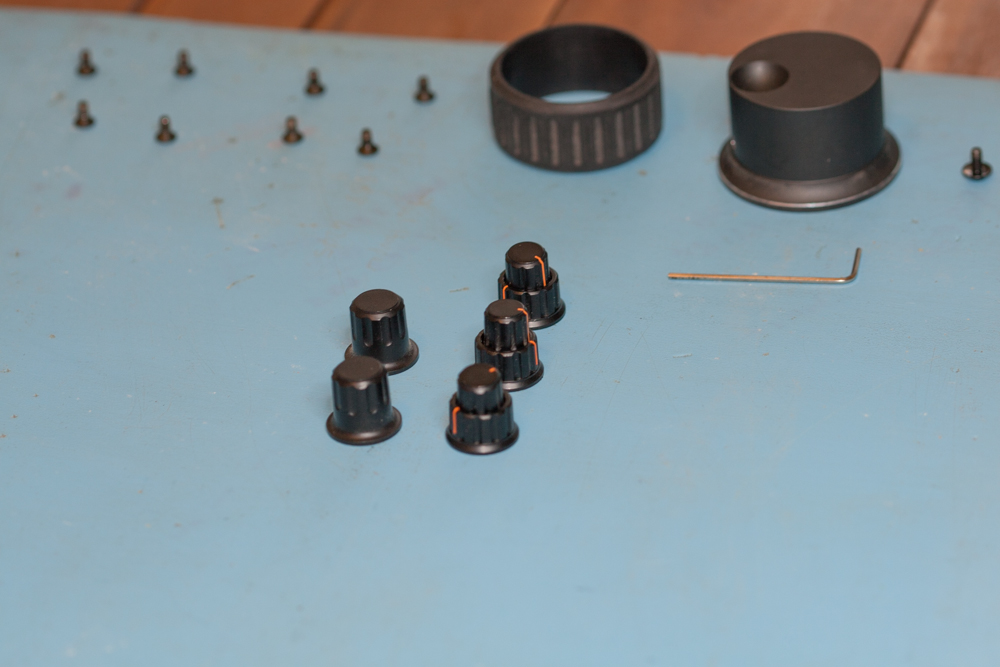
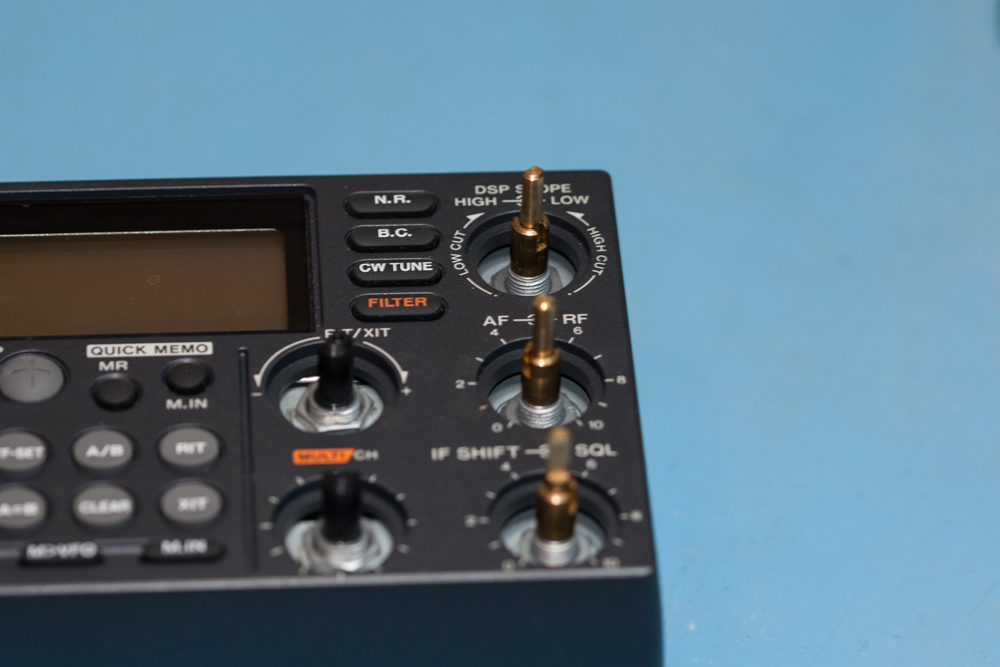
Remove the nuts off the outer three controls using the 7/16″ (11mm) socket, these are the ones with the gold metal shafts and not the black plastic shafts.
They should be only hand tight.
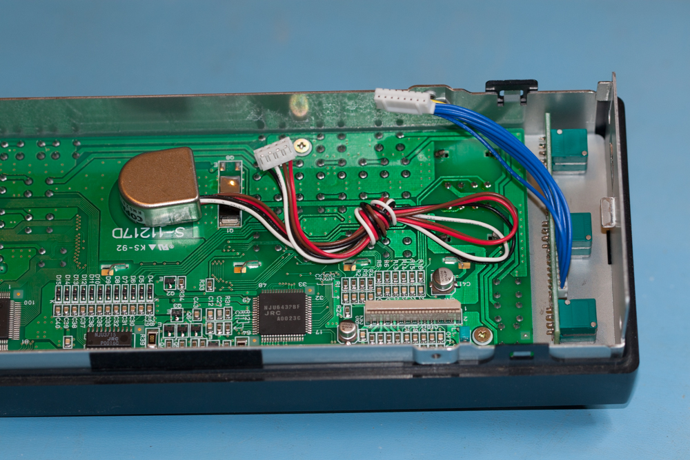
Make a note of the orientation of the switch panel to help you put the unit back at a later date. This unit does fit on the other way up and you don’t really want to waist time taken the whole front end apart again at a later date.
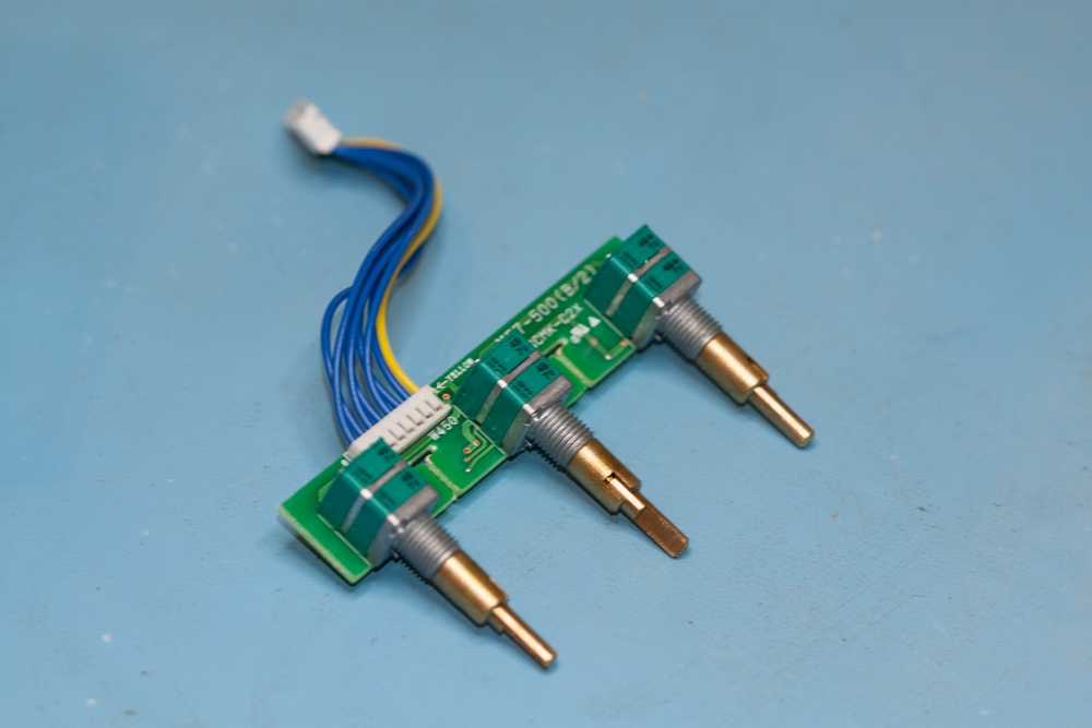
You can now remove these from the front panel and place somewhere safe.
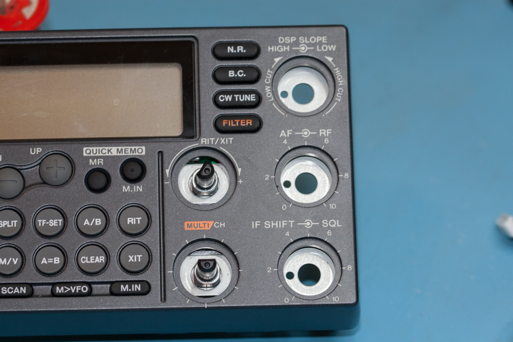
Now remove the nuts from the inner two knobs and place them somewhere safe along with all of the other parts that you have already removed.
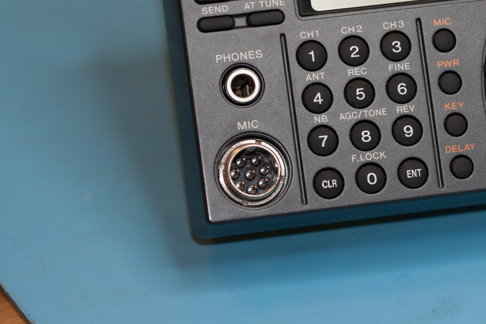
We now need to remove the outer nut from the MIC socket of the Kenwood TS-570D.
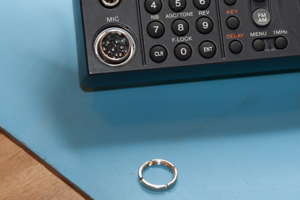
To remove this you just need to use a small watchmakers screwdriver , with a few gentle taps from the palm of your hand you will find that you can easily loosen up the nut and then remove it.
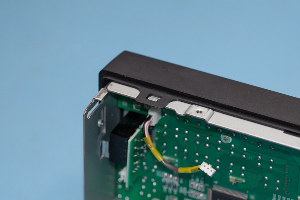
Gently lift up the four catches that hold the plastic display panel onto the metal back plate, make sure that you do not apply too much pressure to these as I am sure that they would break off if you did and you do not want this to happen.
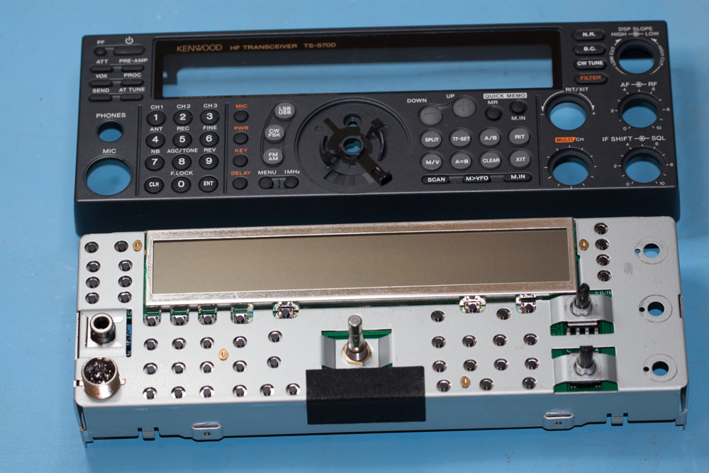
You should now be able to lift of the front plastic face panel of the Kenwood TS-570D from the metal back plate, once done set aside the plastic face place so that you do not damage it or get it scratched.
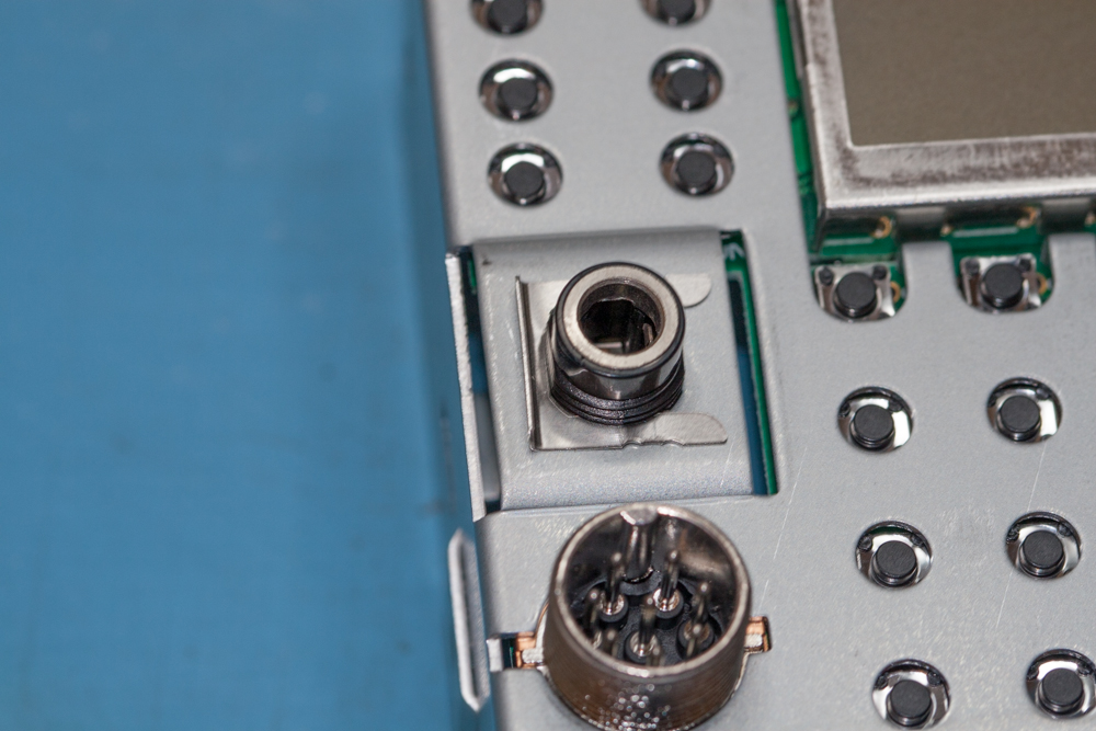
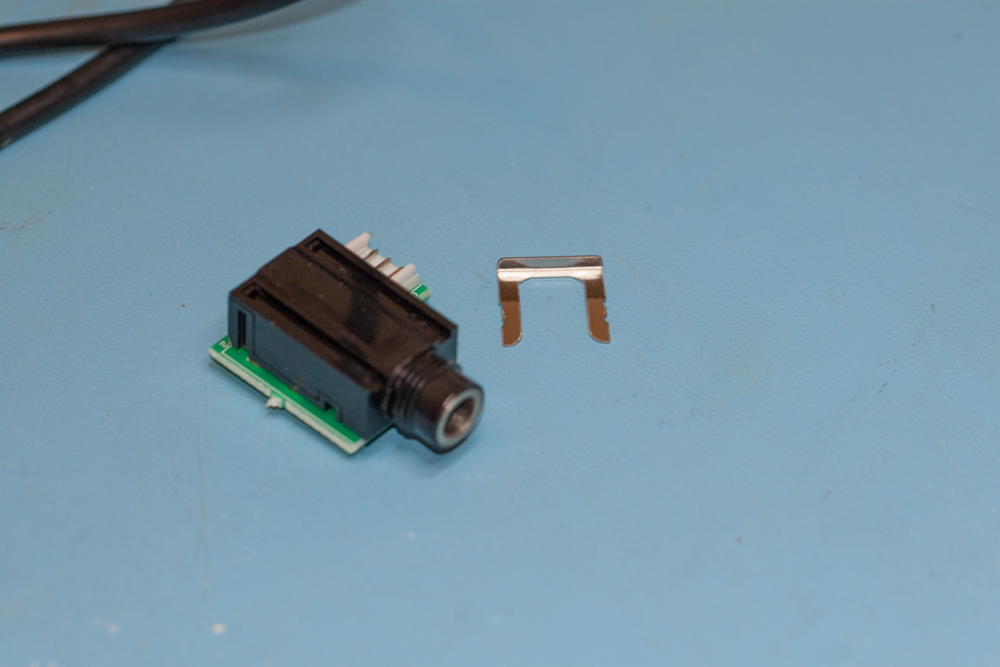
You will notice that there is a small metal clip that hold the headphone socket in place, this can be removed by gently pulling with a set of small long-nosed pliers.
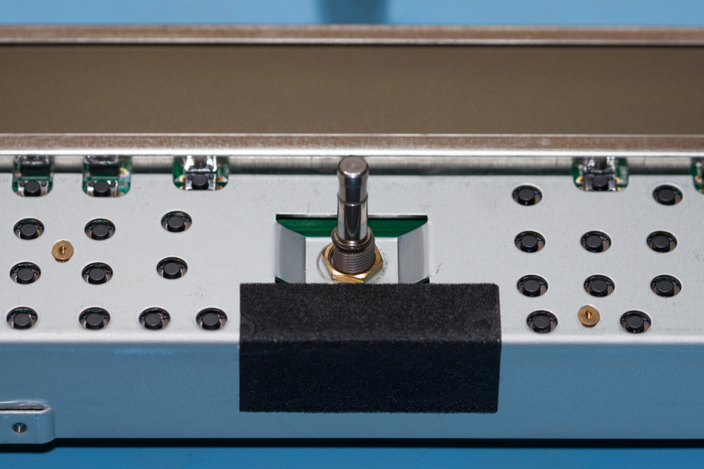
We now need to remove the nut that holds the VFO knob in place.
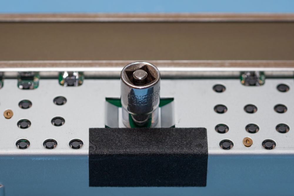
This can easily be achieved by using the 7/16” (11mm) socket to remove the outer nut from the VFO knob.
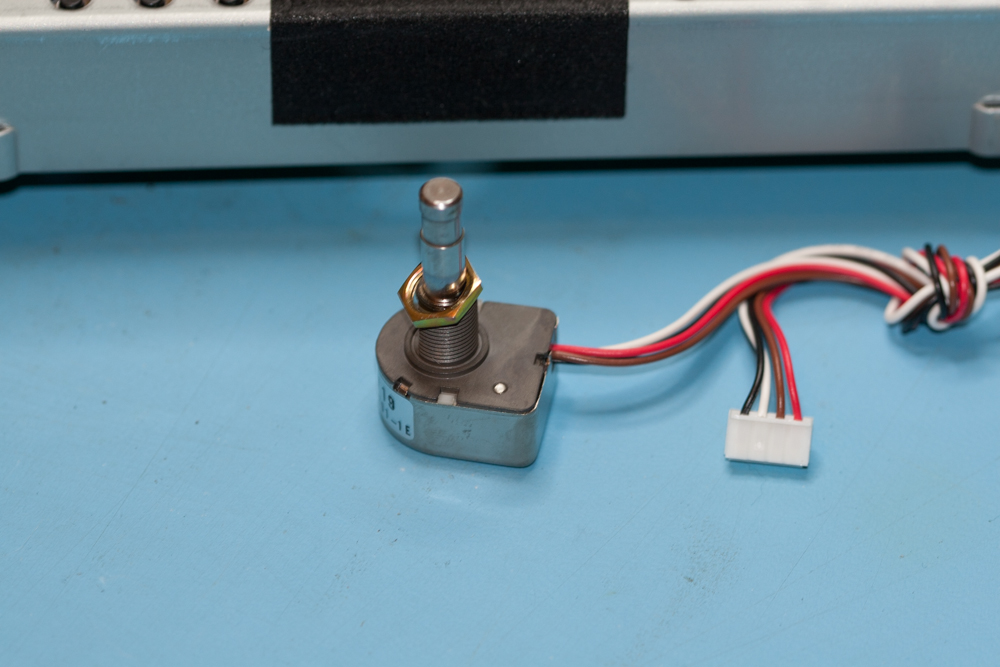
Place the outer knob over the removed VFO shaft so as not to lose it.
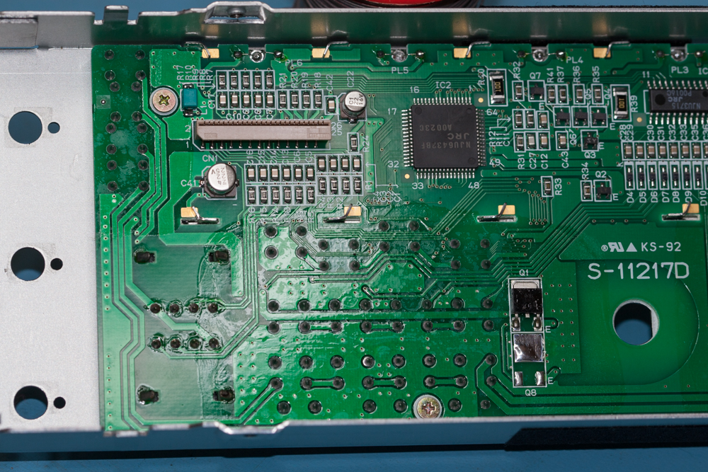
There are four small gold coloured screws that hold the display PCB into the metal case, remove the four screws and place them somewhere safe.
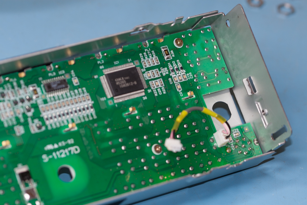
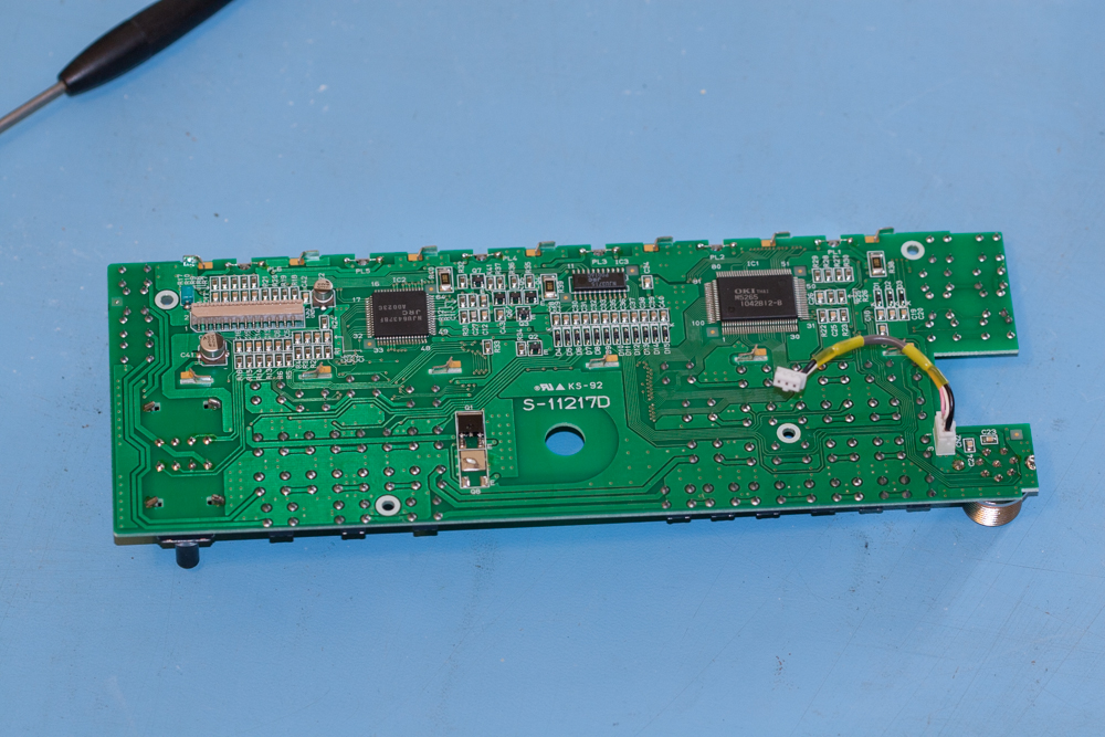
Carefully lift the PCB out of the metal case and put the metal case somewhere safe.
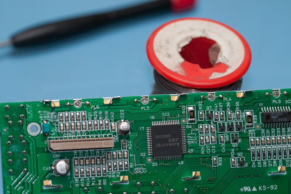
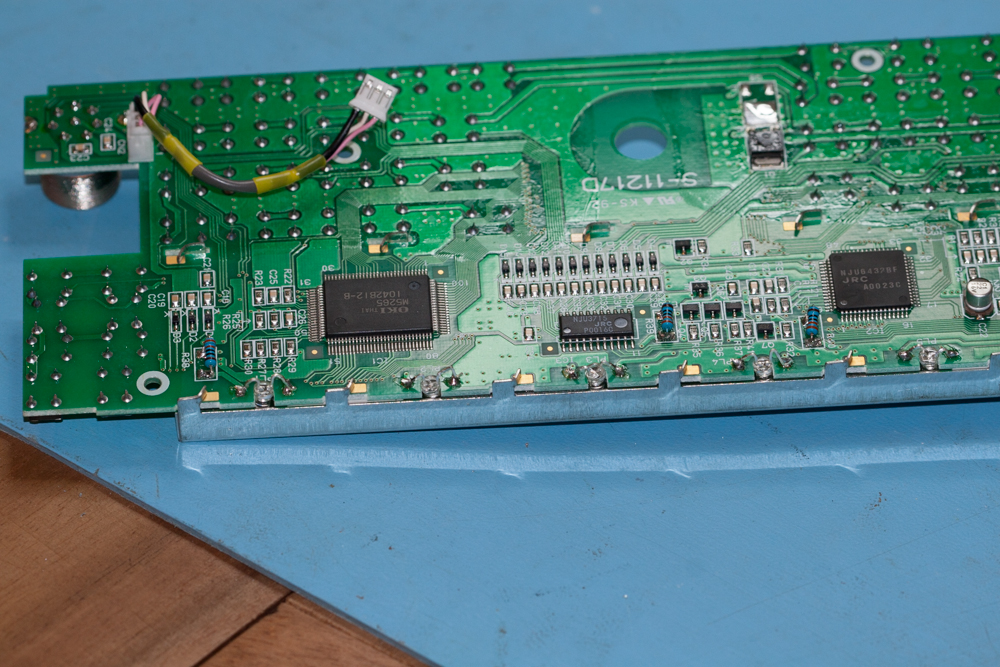
I have positioned the board in an upright position so as you can see the parts that I am pointing out, there are presently six pilot lamps soldered onto the top of the PCB as indicated in the picture below.
I have positioned the board in an upright position so as you can see the parts that I am pointing out, there are presently six pilot lamps soldered onto the top of the PCB as indicated in the picture below.
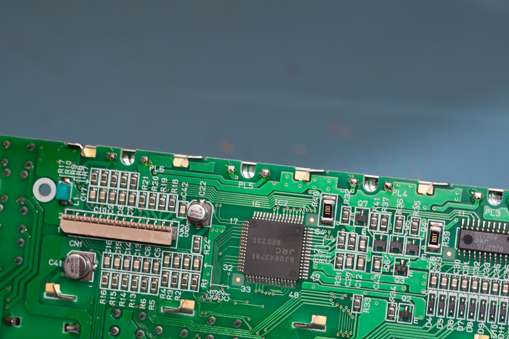
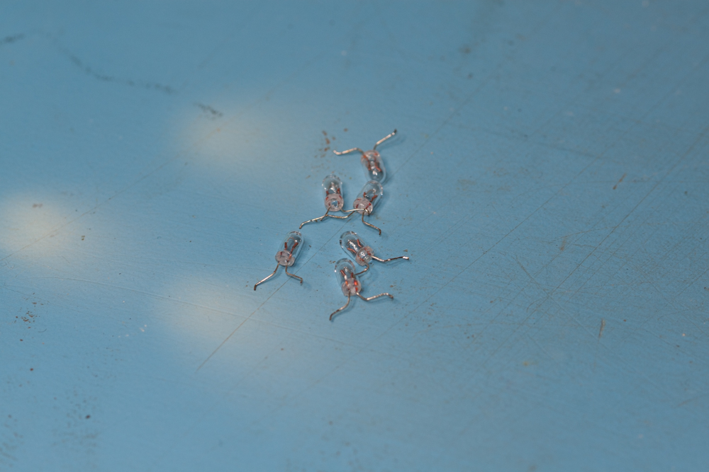
Using either a solder sucker or solder wick carefully remove the solder from each of the legs of each of the pilot lamps, you may need to go over each of the solder pads afterwards to make sure that they are free of any of the old solder.
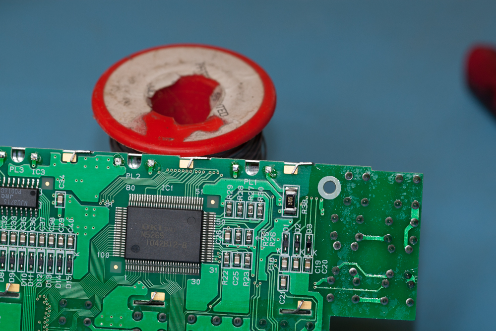
Make sure that the tip of the soldering iron is clean and hot and then place a small amount of solder on each of the pads ready for the new LED’s.
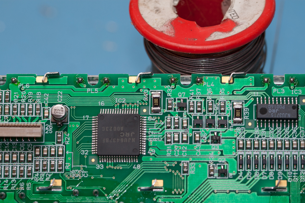
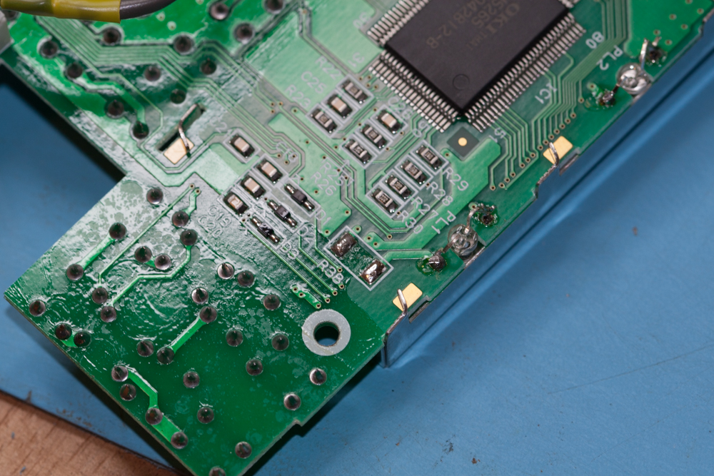
Now remove the three surface mounted resistors, these are labelled R40, R39 and R38, they are all marked ‘100’.
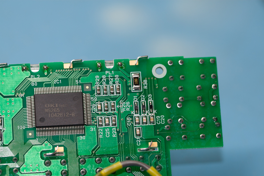
These can easily be removed by removing the solder on one end of each of them and then gently lifting them up from the board and applying a small amount of heat to the other end of the resistor, once this has been done they should easily be removed.
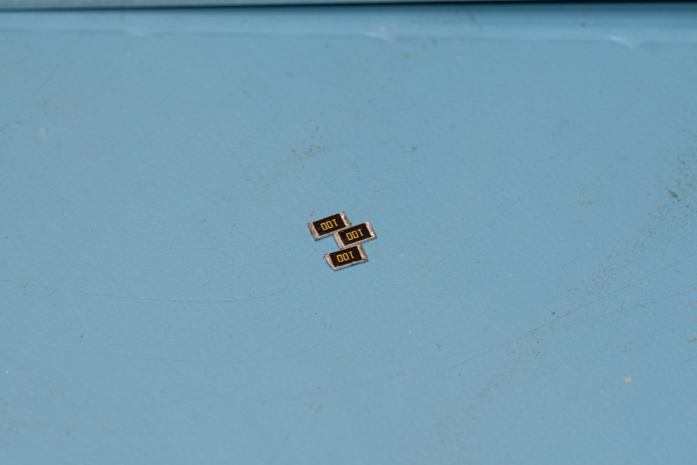
Store them in a safe place as these will be needed if you ever want to reverse the modification.
Before actually soldering them into place, please make a note of the polarity of each of the LED’s, all LED’s are polarity sensitive and although you may not damage them by installing them the wrong way round, you just might!
PLEASE NOTE: The last two LED’s are mounted the other way round from the previous four.
We now need to mount the LED’s onto the PCB of the Kenwood TS-570D.
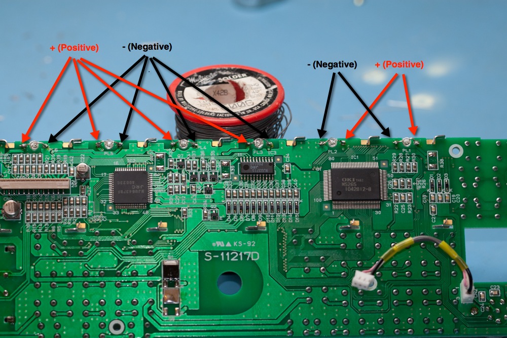
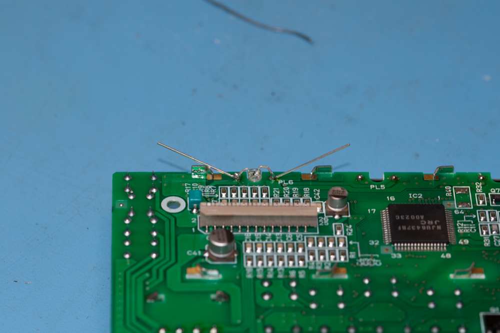
Be very careful with the legs of the LED’s as with this amount of bending it could be fairly easy to break the legs off from the base of the LED. So carefully twist each leg using the small long-nosed pliers.
These first need to be bent into the same shape as shown here, this is to make sure that each LED is positioned as far to the back of the PCB as possible so that you don’t get any glare from the LED’s onto the front display glass.
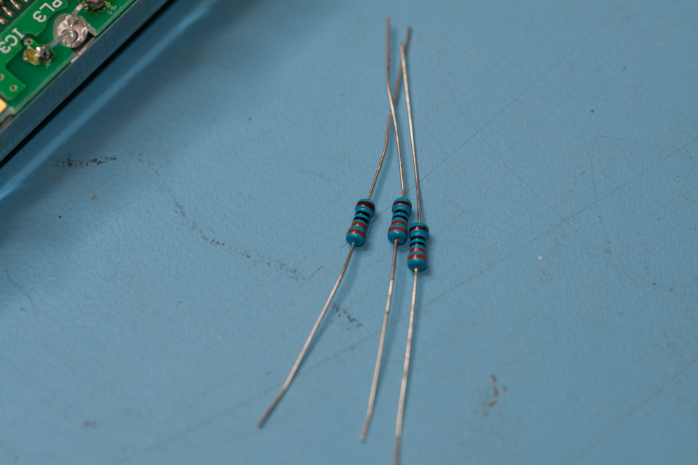
With all of the LED’s now mounted we can now mount the resistors.
Place a small amount of solder onto the three pairs of pads where the resistors will be inserted.
As like we did before with the pilot lamp pads, we need to prepare the resistor pads for the new resistors.
Its not pretty using these type of resistors, but this is what was supplied in the kit and at the time I did not have the correct SMD type to fit instead, they will do and they will do the job for the moment, I can always revisit this at a later time and fit the correct type then.
Solder each of the three resistors into place.
Bend each of the legs of the resistor under itself and place up against the pads where we will end up soldering it too, this will enable you to cut the legs off the resistor before installing it.
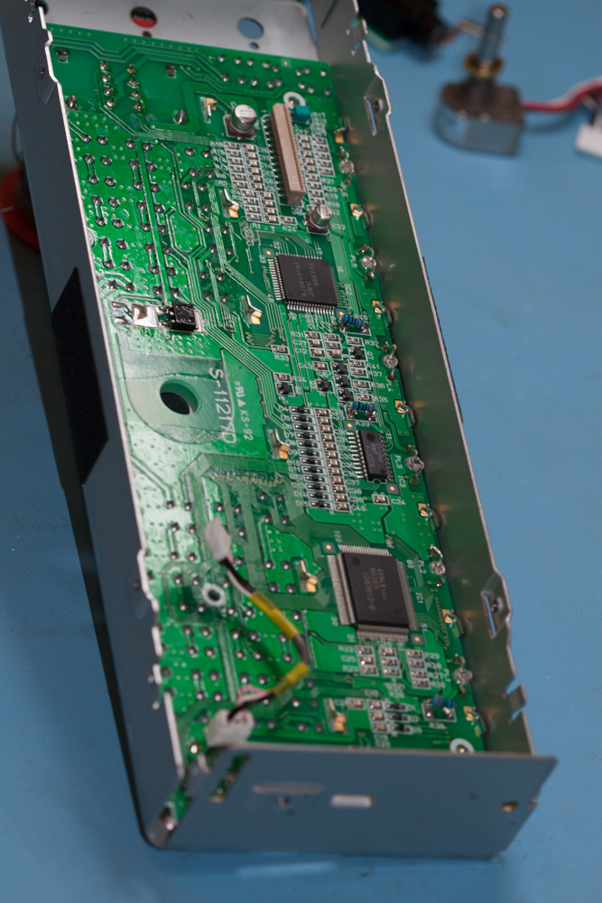
Carefully place the display PCB back into its metal case and make sure that none of the new LED’s leads touch the metalwork.
That’s all of the soldering done, just check over your joints to make sure that your work is OK.
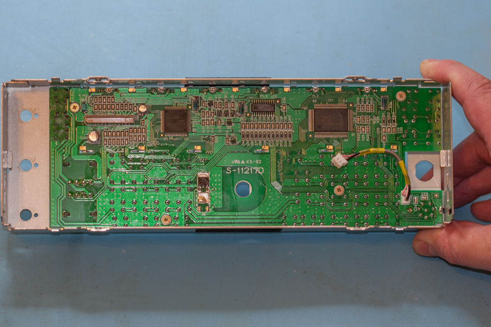
Replace the four gold screws to fix the PCB in place.
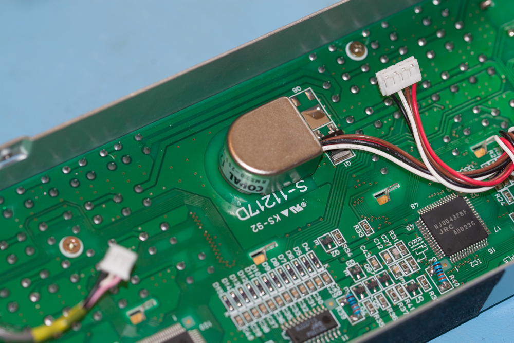
Now fit the VFO knob back into its hole in the Kenwood TS-570D and affix with its nut, this obviously needs to be tightened, up, make sure that this is not done too much, a strong hand-tight will suffice.
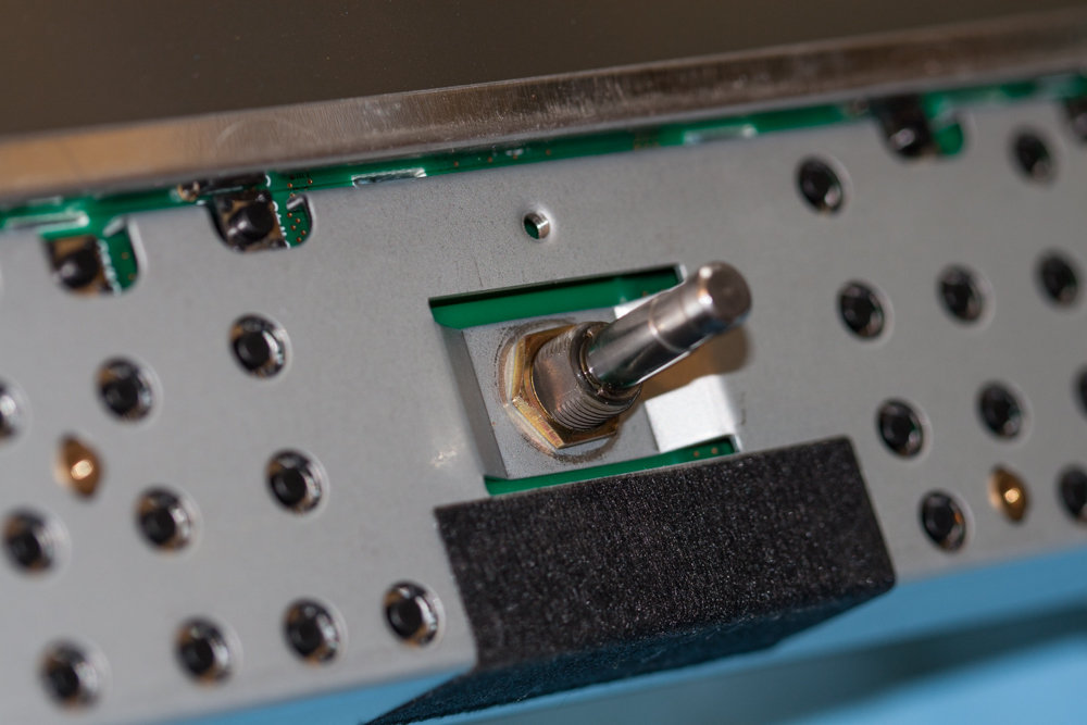
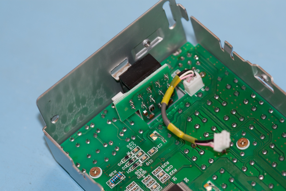
Now re-fit the headphone socket, make sure that the orientation is the same as the image to the right.
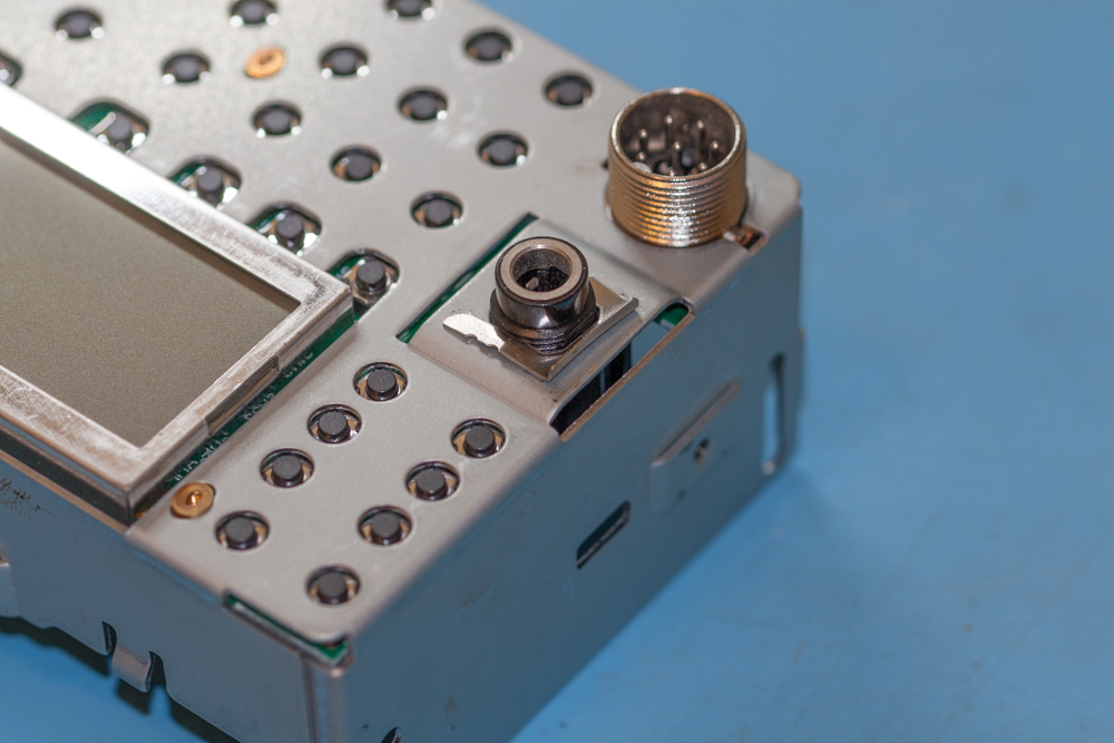
Whilst holding the headphone socket with your fingers, carefully push the clip onto the socket so that it fits in the grove on the socket.
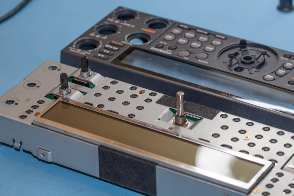
We are now ready to put the plastic display back onto its metal mountings.
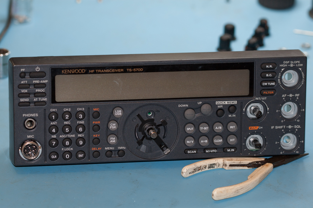
This is very quick and simple, you just need to make sure that all of the four clips are securely pushed home.
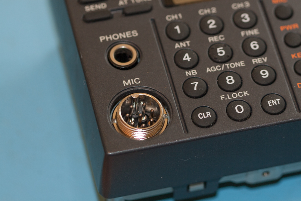
Now replace the nut around the MIC socket, this can be tightened with the watchmakers screwdriver as tight as possible, and then gently tap the screwdriver to make it as tight as it needs to be.
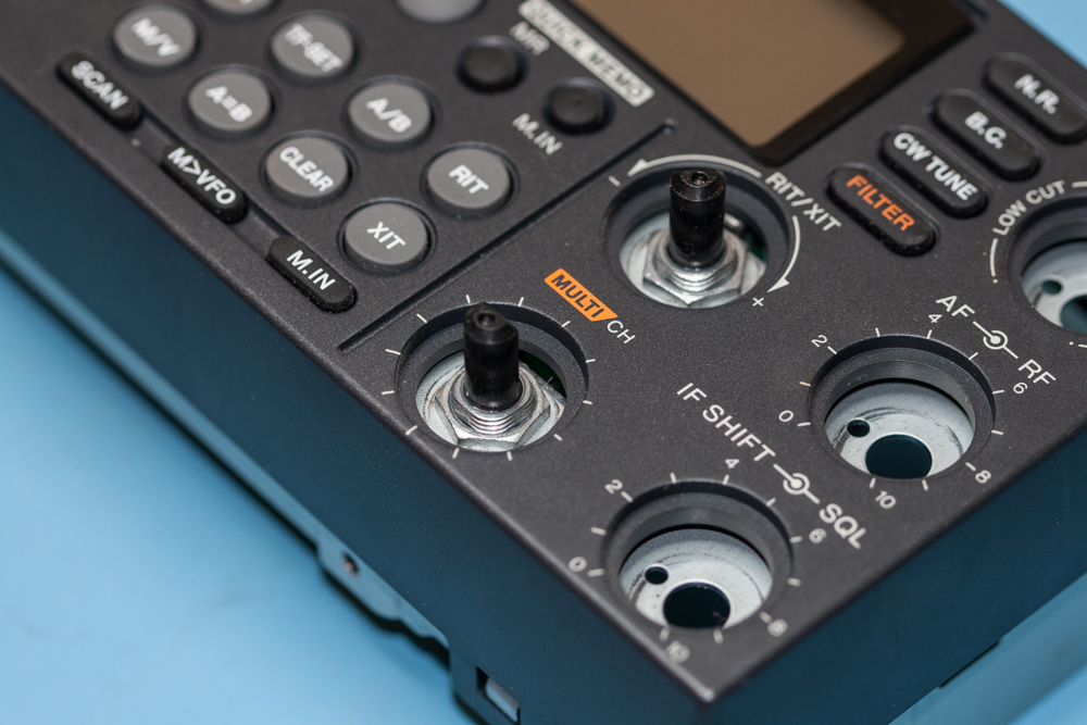
Now replace the nuts on the two innermost controls.
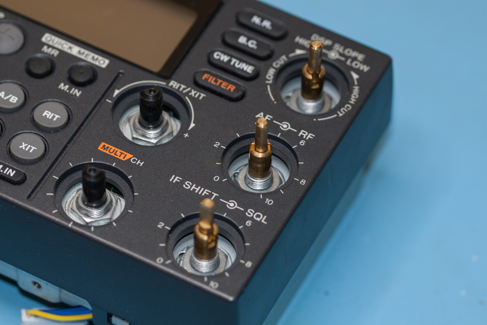
Now replace the nuts on the three outermost controls.
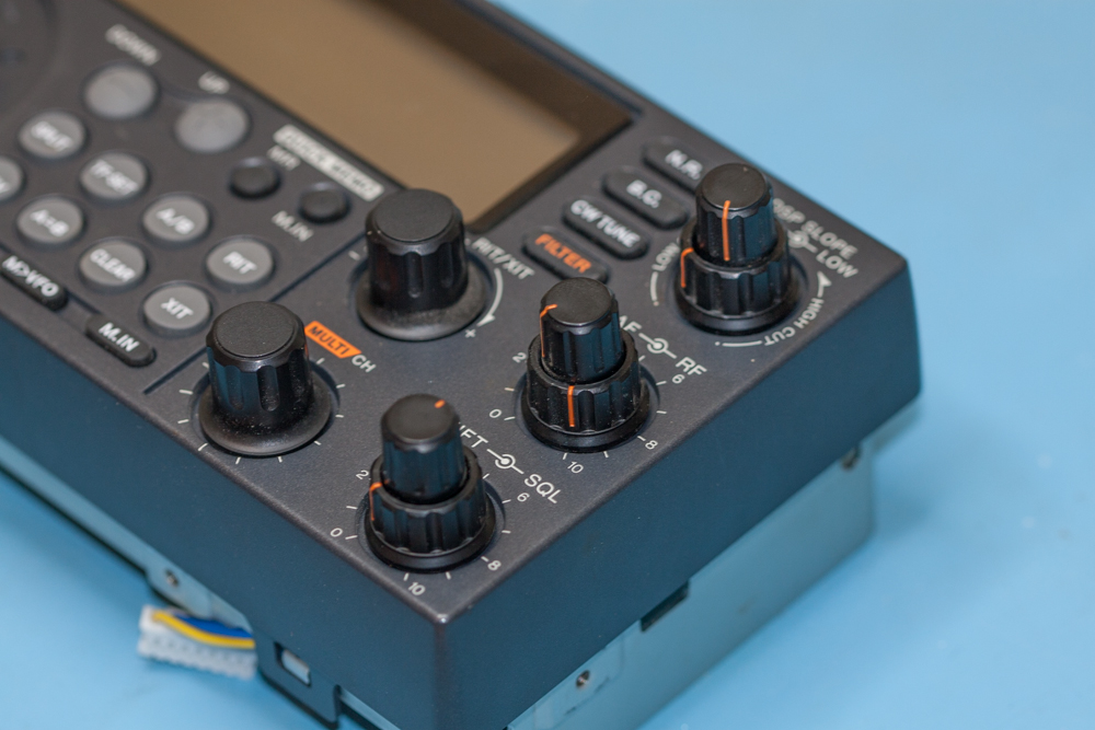
You can now re-fit all of the plastic knobs.
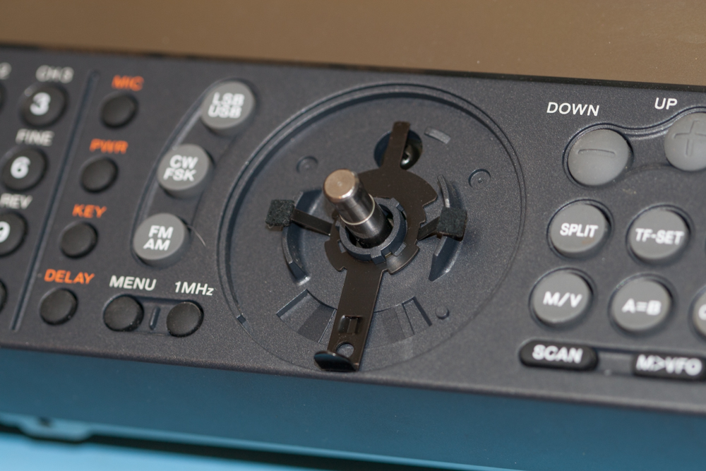
Now re-fit the screw behind where the VFO knob is fitted and return the metal plate to its original position.
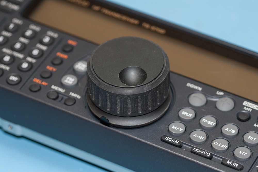
Now put the actual VFO knob back onto its spindle and tighten up the Allen screw that holds it in place, this time maybe not as tight as it was done previously…
Re-fit the rubber onto the knob and that’s it! All done!
Before fitting the covers, apply power to the unit and hold your breath, switch on the unit, and (hopefully) smile.
The finished Kenwood TS-570D Blue LED Display Mod.
