Kenwood R-600 Display Repair
A little while back Harry Blackburn (MD0HEB) asked me if I would take a look at an old receiver that he had lying around, the unit was an old Kenwood R-600 that he used for listening to the local Manx Radio on AM, but just recently it had started to through a little problem his way, in that the display would not read correctly or at all.
So there was nothing else for it, but to take the unit part and see if we could locate the fault!
I removed the top cover along with it’s handle that by the way does not need to be removed, and once this was removed and placed somewhere safe, I then removed the bottom cover as well, again putting this somewhere safe for later.
Now that it was accessible, I seas able to carry out some tests on the unit, using both an antenna for external reception, and also known signal sources via the RF Frequency Generator which was coupled to both a Spectrum Analyser and a frequency Meter to confirm that the receiver should be hearing the signal at the frequencies that I was sending the finals into the receiver at! This may sound a little overkill, but actually it isn’t, and that said, the little receiver in the end was spot on, as far as the recover itself, but the display when working was just all over the place, and more often that not it would not work at all.
This was screaming ‘Dry Joint’s’ out to me, but where?
I did a bit of digging on the web for a service manual and came across an interesting article on a website run by the Highfields Amateur Radio Club that is no longer there when you read this in 2021 onwards.
Anyway – They had reported a VERY similar problem…
They had checked the Power Supply, which I did also and mine was also found to be OK, then following what they had done I checked out the voltages around TP4 (Test Point 4) on the PLL board and just like there’s, they were not what the Service manual stated. So this is a common issue…..
As per there website (Sorry guys I copied and pasted this bit! – Hope that you don’t mind), taking the voltage at TP4 …
According to the service manual on band 3 and band 11 it should be 3.8V, on band 25, 5.5V and band 29, 7.6V. No matter what band I selected it was over 8V!
Mine at one point was nearer 9V, but was more or less the same.
As per what he had done I also checked the output from Q39 (µPC14305 or 5V 1A regulator that supplies the frequency read out and PLL circuitry) which showed 4.4V well mine was 4.8V which was close to his reading of 4.4V.
At this point it was recommended to grab a cup of coffee and look for an article written by VE1BLL, Dam good idea, the coffee that is…
As for the article, the only thing that I could find was on eHam, check out the few lines of text at this link:
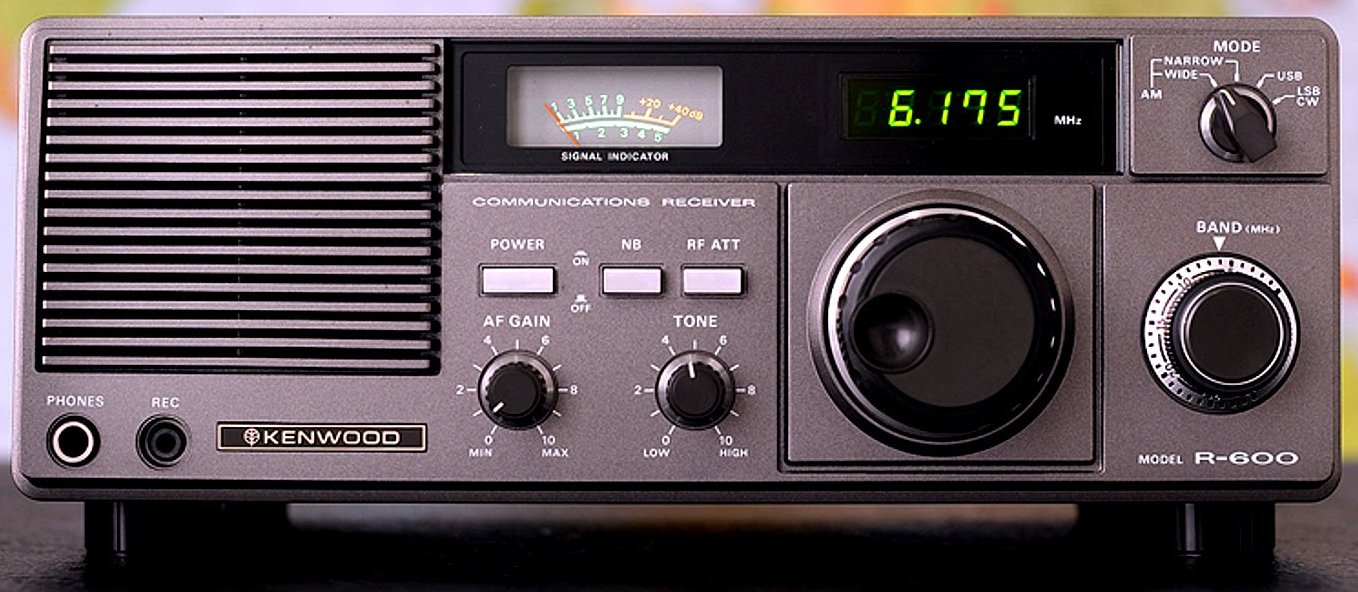
The Voltage Reg is attached to this Heatsink!
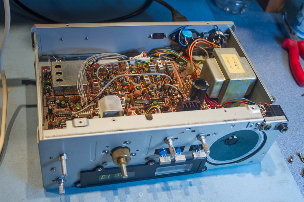
Ok, Now please excuse the photos in this article, they are so out of sync, I had only thought about taking photos of the unit when I had taken the PCB out of the unit, so these photos are actually from that time onwards and show the receiver working, so please ignore this slight cock-up by me…
So just in case no-one read the eHam article, it said the following:
The solder joints on the 3-terminal voltage regulators became intermittent due to cracked solder joints. The root cause was the way that the heat-sinks were installed so that expansion of the AL heatsink fatigued the solder joints. I fix it by reinstalling the VRs upside down with jumpers. The symptom was an unlocked PLL and it sounded like the tuning knob was going a mile a minute.
So as this had seemed to fix two of these units now, I decided that I would have to take the board out of the unit.
To remove the PLL board we will need to remove the front panel, this is actually the easy bit, just a few screws top and bottom hold the front panel to the metalwork. Once these are removed and placed somewhere safe you can move on to removing the knobs, at this point looking back at the Highfields website helped me out here as they state that all of the knobs except for the ‘Band’ knobs are pouch fit, and with a little persuasion should just pull off, the Band knob will need a grub screw loosening off with a 2mm allen key.
The last two screws to remove are the two that where under the main VFO knob.
The front panel can now be removed.
Next remove the nut and washer holding the band switch to the metal chassis.
Now for the slightly harder part. If you are not too happy about remembering where things go, Take a photo or two, or even three, they are free, and they will save you a lot of heartache later when you forget where cables were plugged in, saying that, this receiver is not too complicated so you may be able to sort this out anyway.
Turn the radio upside down and unplug all the plugged wire connections.
Remove the 9 screws that hold the board in place, the board will now be free to be removed from the chassis, it will take a little maneuvering, just be patient and it will come out.
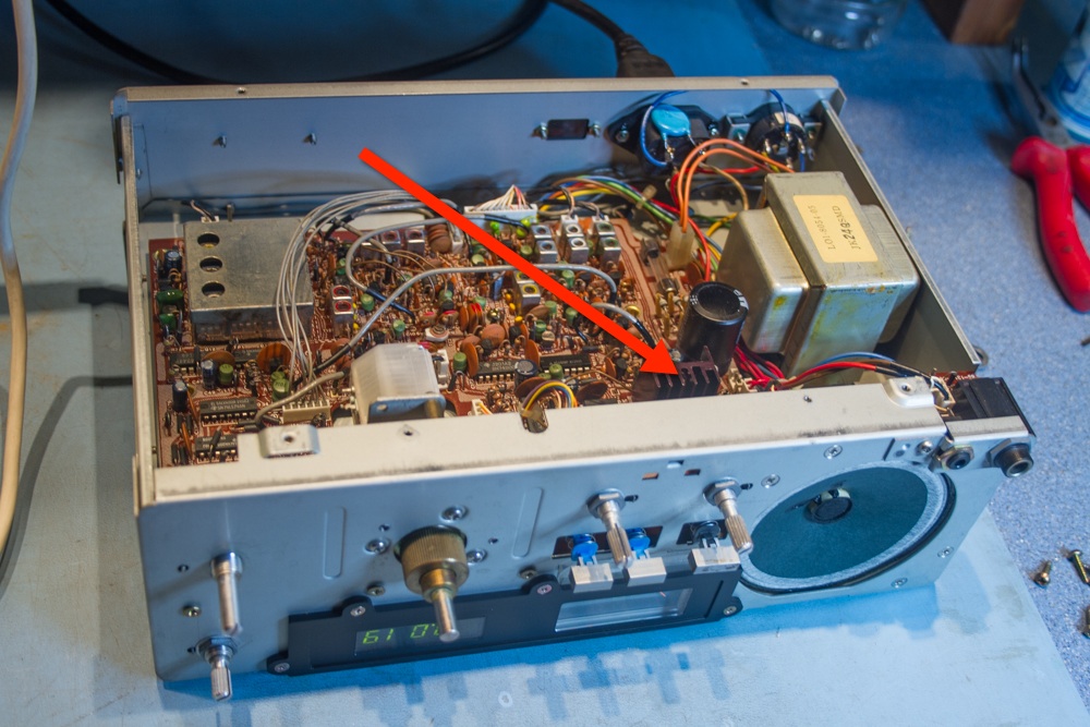
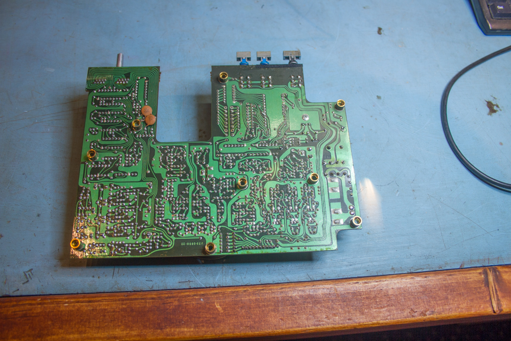
What you will be left with is an empty chassis…
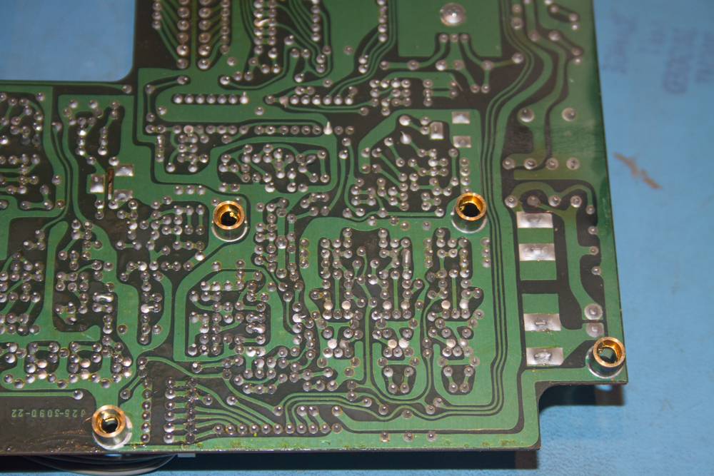
And a dusty old PCB in your hands…
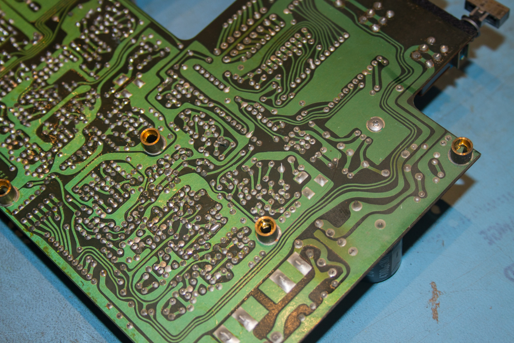
In the article on the ‘Highfields Amateur Radio Club’ website, Brian explained that he could actually see cracks, my problems were not as easy to see, but I could already see that the solder was very dull and not as clean as solder should be, and then after many years of being used and sat in a dusty garage shack you may expect this, but certainly looking around the section where the regulator sits, the solder was certainly a lot duller than the rest of the boards, so I assume that we are certainly looking at a few possible ‘Dry Joints’, nothing that a good solder could not help fix.
I removed as many joints that I was happy to, and then resolver each in turn, once this area was done, I gave a long glance over the rest of the board and did a few others whilst the board was pout of the unit.
Again taking Brian’s lead, I refitted the board by just doing what you did to remove it in reverse, and then once done, I just screws the board down in two locations to keep it in place, then once all of the connections have been reconnected I switched on the unit to test.

And just like Brian I tuned the radio into nearby radio stations and sure enough, all was working as it should along with the frequencies appearing on the display.
I then rechecked the voltage at TP4 as per Brian’s instructions and mine were as they should be, so well happy.
This fix seemed to have been one of the easiest to diagnose, mainly thanks to Brian Perrett’s (MW0GKX) piece on the ‘Highfields Amateur Radio Clubs’ website, and of course Jeffrey Harvey’s (VE1BLL) few helpful notes on eHams site. This is exactly what any Amateur Radio Club’s website should have on their sites, helpful hints, guides and articles that others will find useful, Thanks guys for the pointers, it was very much appreciated…