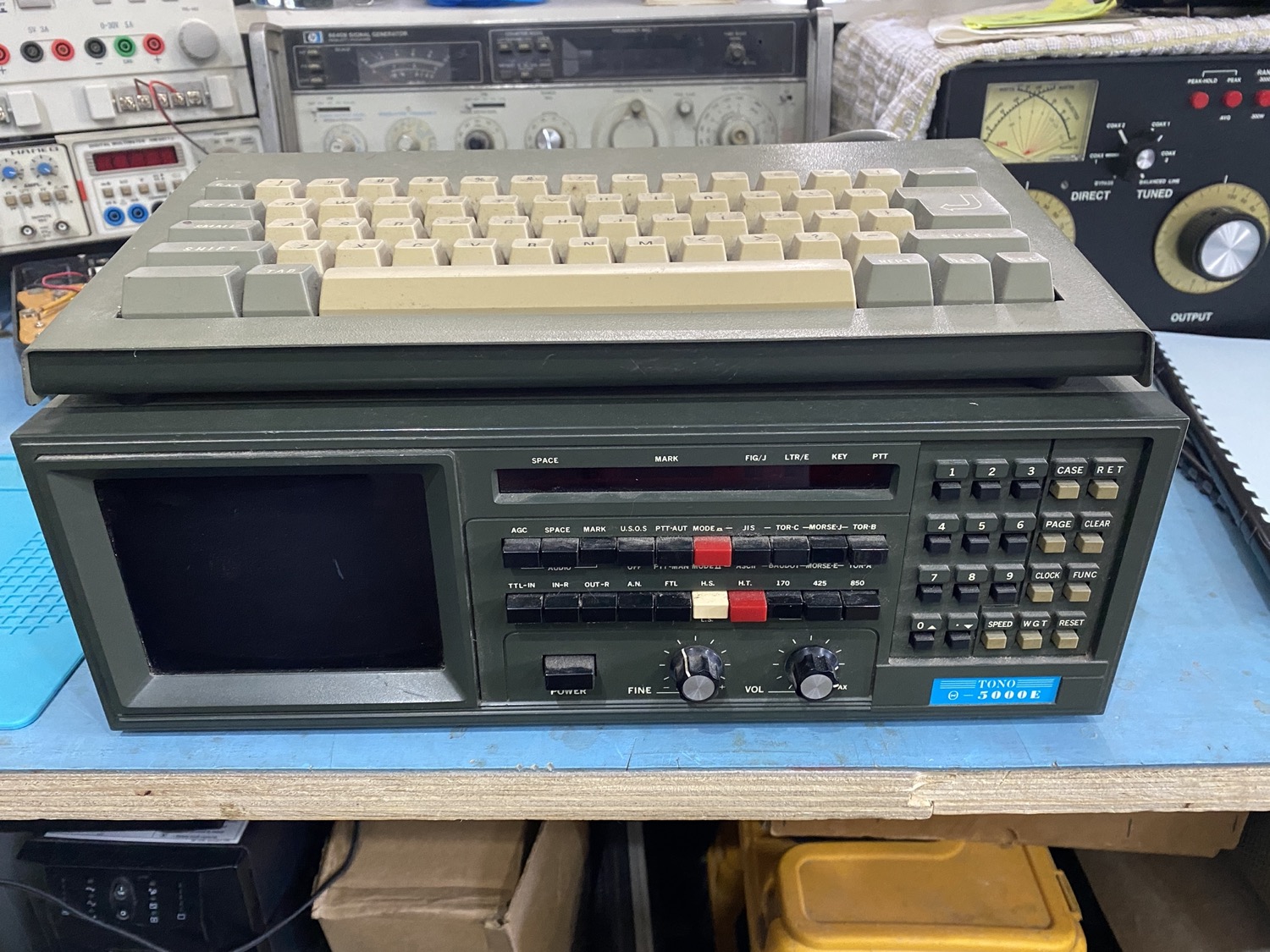
TONO THETA 5000E Sender-Decoder
This Page is more ‘Born out of Need’ than anything else. I have not Used one of these now for over 9 Years back, so items such as the configuration and then actually getting it to work with my Drake T-4X, this was because 9 years ago I handed all my kit to a very good friend and therefore I did not use this unit as all my other gear used much more modern interfaces such as the MicroHam devices. So this is here basically to help me out…
I am going to add the entire manual up here and if I need at add any useful or even not so useful comment I will do this with quotedcomments.
The Instruction Manual (2nd Edition)
FEATURES OF THETA-5000E
With the most up-to-date computer technology, just a Terminal and a Keyboard allow complete automatic send/receive of Morse Code (CW), Baudot Code (RTTY), ASCII Code (RTTY) and New ARQ/FEC (AMTOR).
When they wrote this t was a long time back, well Nowadays it is not ‘New Technology’, but at least it made me chuckle.
Built-in Monitor
5-inch High-Resolution Green Monitor is Built -in, the unit even has the provision for a Composite Video Signal output.
ARQ/FEC Feature
AMTOR A, B and L communication is Possible.
Time Clock Built-in
Display Month, Date, Hour and Minute on the Display Screen.
Timer Transmission / Receiving Feature.
The Inner Timer enables complete automatic TX/RX.
Selcal (Selective Calling) System.
With the feature the unit only receives messages following the Preset Code.
Built-in Demodulator for High Performance.
Newly designed high speed RTTY demodulator has receiving capability of as fast as 300 bauds. Three-step shifts selects either 170Hz, 425Hz or 850Hz shift with manual fine tune control of space channel for odd shifts. HIGH (Mark Frequency 2125Hz / LOW (Mark Frequency 1275Hz) tone pair select. Mark only or Space only copy capability for selective fading. ARQ/FEC feature newly incorporated.
Crystal Controlled AFSK Modulator
A transceiver without FSK function can transmit RTTY mode by utilizing the high stability crystal-controlled modulator controlled by the computer.
Optoisolator CW, FSK Keyer built-in
Very High-Voltage, High-Current optoisolator keyer is provisioned for CW, FSK keying.
Automatic Transmit / Receive Switch
The Transmit / Receive switch is controlled by the microprocessor. Built-in remote control key function automatically controls the Transmit / Receive circuitry of the transceiver. Manual operation is also available.
Battery Backup Memory
Data in the Battery Backup Memory, covering 72 characters x 7 Channels and 24 characters x 8 Channels, is retained even when the external power source is removed. Messages can be recalled from a keyboard instruction and some channels can be read out continuously. You can write messages into any channel while receiving.
Large Capacity Display Memory
Covers up to 1,280 characters. Screen format contains 40 characters x 16 lines x 2 pages.
Screen Display Type-Ahead Buffer Memory
A 160 character buffer memory is displayed on the lower part on the screen. The characters move to the left, erasing one by one as soon as they are transmitted. Messages can be written during the receiving state or the performance with battery back-up memory or SEND function.
Pre-loud Function
The buffer memory can store the messages written from the keyboard instead of sending them immediately. The stored messages can be sent with a keyboard command.
‘RUB-OUT’ function
You can correct mistakes while writing messages in the buffer memory. Misspellings can be erased while the information is still in the buffer memory.
‘SEND’ function
Sends the transmit text displayed on the screen, including the data stored in every channel of the battery back-up memory, with a command from the keyboard. The messages can be stopped and easily restarted.
Function Display Screen
Each function (mode, channel, number, speed, etc.) is displayed on the screen.
Wide Range of Transmitting and Receiving
Morse Code transmitting speed can be set from the keyboard at any rate between 5 100 WPM (every word per minute). AUTOTRACK on receive. For communication in BAUDOT and ASCII Codes, rate is variable by a keyboard instruction between 12 300 bauds when using RTTY Modem and between 12 600 bauds when using TTL level.
The variable speed feature makes the unit ideal for amateur, business and commercial use.
Automatic CR/LF
While transmitting, CR/LF is automatically sent every 64, 72 or 80 characters, as selected.
Cursor Control Function
Full cursor control (up/down, left/right) on the transmitting screen is available from the keyboard.
WORD MODE Operation
Characters can be transmitted by word groupings, not by every character, from the buffer memory with the keyboard instruction.
LINE MODE Operation
Characters can be transmitted by line groupings from the buffer memory.
WORD-WRAP-AROUND Operation
In receive mode, WORD-WRAP-AROUND prevents the last word of the line from splitting in two and makes the screen to be easily read.
Automatic Idle Signal Insertion
Idle signal (letters code) can be automatically inserted in a pause of transmission in BAUDOT-RTTY mode.
“ECHO” Function
With a keyboard instruction, received data can be read and sent out at the same time. This function enables a cassette tape recorder to be used as the back-up memory, for operation just like telex (which uses paper tape).
Test Message Function
“RY” and “OBF” test messages can be repeated with this function.
CW Identification Function
In RTTY mode, keyboard-controlled CW identification is available if required.
MARK-AND-BREAK(SPACE-AND-BREAK) System
Either mark or space tone can be used to copy RTTY.
Variable CW Weights
For CW transmission, weights (ratio of dot to dash) can be changed within the limits of 1: 3 1:7.
CW Practice Function
The unit reads data from the hand key and displays the characters of the screen. CW keying output circuit works according to the key operation.
CW Random Generator
Output of CW random signal can be used as CW reading practice.
Audio Monitor Circuit
A built-in audio monitor circuit with an automatic transmit / receive switch enables checking of the transmitting and receiving state. In receive mode, it is possible to check the output of the mark. filter, the space filter and AGC amplifier prior to the filters.
Printer Interface
Centronics Parallel Comatible interface enables easy connection of a low-cost dot printer for hard copies.
Convenient ASCII Key Arrangement
The keyboard layout is ASCII arrangement. Automatic insertion of LTR/FIG code simplifies operation.
Bargraph LED Meter for Tuning
Tuning of CW and RTTY is very easy with the bargraph LED meter for tuning.
Provision has been made for attachment of an oscilloscope to aid tuning. This supplements the tuning bargraph LED and audio monitor provided in the system.
Both AC/DC Usable
Power Supply is switchable as required; 100-120V AC / 220-240V AC / +13.8V DC .
1. INSTALLATION
1.1 Keyboard Controls
This section will assist you in becoming familiar with the keyboard controls.
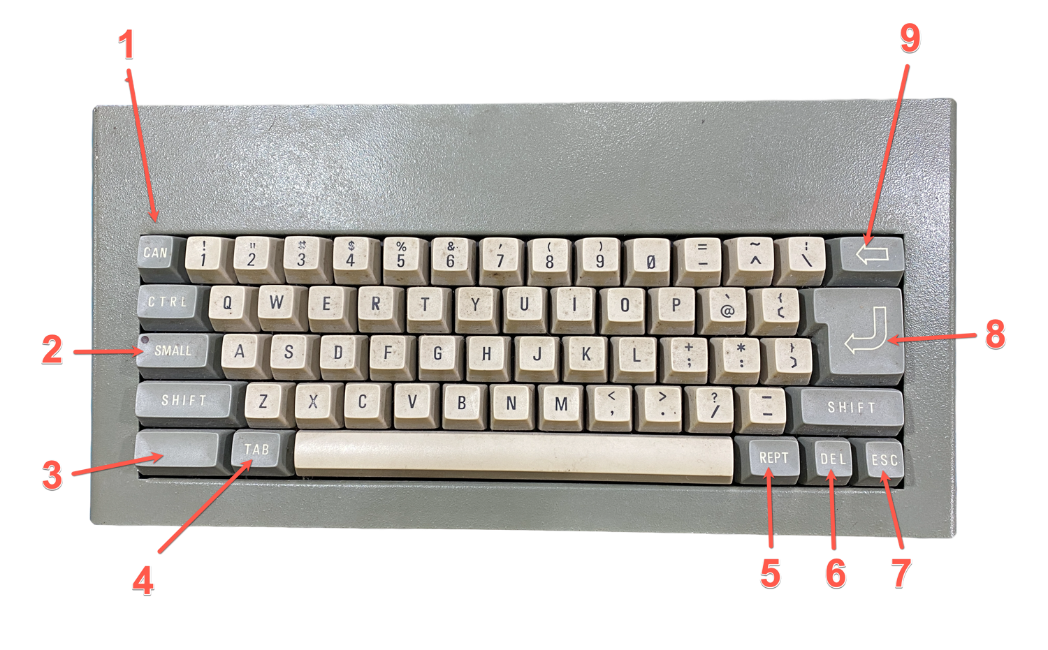
1 – ‘CAN’
- Transmits a Japanese Kana Glyphe in CW Mode. After the transmission the unit selects and locks in Japanese Kana Characters.
- Transmits FIG in BAUDOT mode and AMTOR modes.
- The keystroke ‘SHIFT-CAN’ cancels the backspace key (9) instructions and returns the unit from the setting state to the ordinary transmit / receive state.
2 – ‘SMALL’
- Selects European characters in Japanese CW Mode.
- In ASCII and JIS modes, the keystroke switches the selection of capital and small letters.
3 – ‘UNMARKED (KANA)’
- In Japanese CW mode, the unit selects Japanese Kana characters.
- In JIS Mode, the keystoke changes the selection of the Kana, alphabet, figures and symbols.
4 – ‘TAB’
- Stops the screen transmission of the data written in Page 2. (PTT is not turned off even when set to PTT=AUTO.)
- With the keystroke “SHIFT-TAB”, on/off of the PTT jack is switched when the PTT jack is set to be manually switched. It inserts automatic stop signal in the buffer and page 2 and turns off the PTT when set to be automatically switched.
5 – ‘REPT’
A function tree for transmission to be used when sending data in battery backup memory, Page 2 ot test messages.
6 – ‘DEL’
- Transmits BT (Overlined) in Japanese CW Mode. After the transmission of BT (Overlined), the unit selects alphabets.
- Transmits LTR Code in BAUDOT and AMTOR modes.
- The keystroke “SHIFT-DEL” allows correction of data written in the buffer memory, battery backup memory or Page 2.
7 – ‘ESC’
The keystroke “SHIFT-ESC” stops transmission immediately. Buffer memory is cleared.
8 – ‘CHARACTER RETURN’ (CR)
Transmits a CR and LF (Line Feed)
9 – ‘BACKSPACE’
The “BackSpace” key is a function key used to set various functions or to write in the battery backup memory and Page 2.
Certain keyboard commands require pressing two keys simultaneously. Such commands are denoted in this manual as, for example, “SHIFT-TAB”. Other commands require pressing two keys, one after the other, but separately. Such commands are donated as for example “RETURN” or “C”.
Front Panel
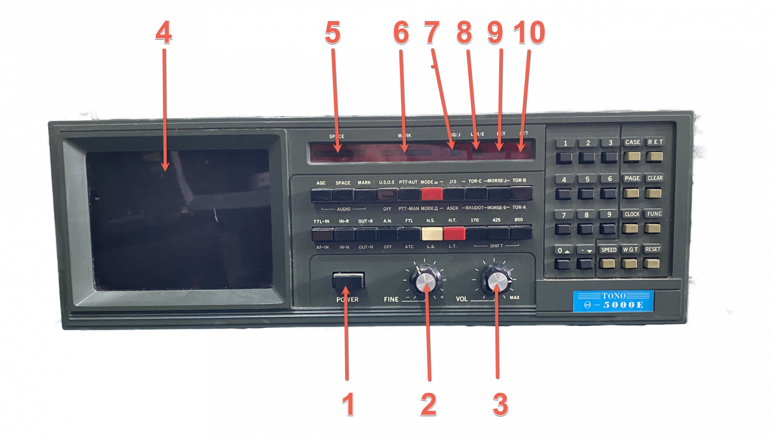
1.2 – Front Panel Keyboard Controls
This section will assist you in becoming familiar with the push button controls on the front panel.
1 POWER switch
Controls all power to the unit. (both AC/DC)
2 FINE tuning
Fine adjustment of the shift width in the RTTY modes or the AMTOR modes.
3 VOLume
Controls the volume of the monitor speaker.
4 CRT Display
.
5 SPACE LED
Indicates tuning of the space filter.
6 MARK LED
Indicates tuning of the mark filter.
7 FIG/J LED
Indicates that FIGURE is selected in the RTTY modes or that Japanese Morse code is selected in the CW mode.
8 LTR/E LED
Indicates that LETTER is selected in the RITY modes or that European Morse code is selected in the CW mode.
9 KEY LED
Indicates that the keying line is in Mark state when the polarity of transmitting signals are normalized.
10 PTT LED
Indicates that the PTT (Push-to-talk) line is on.
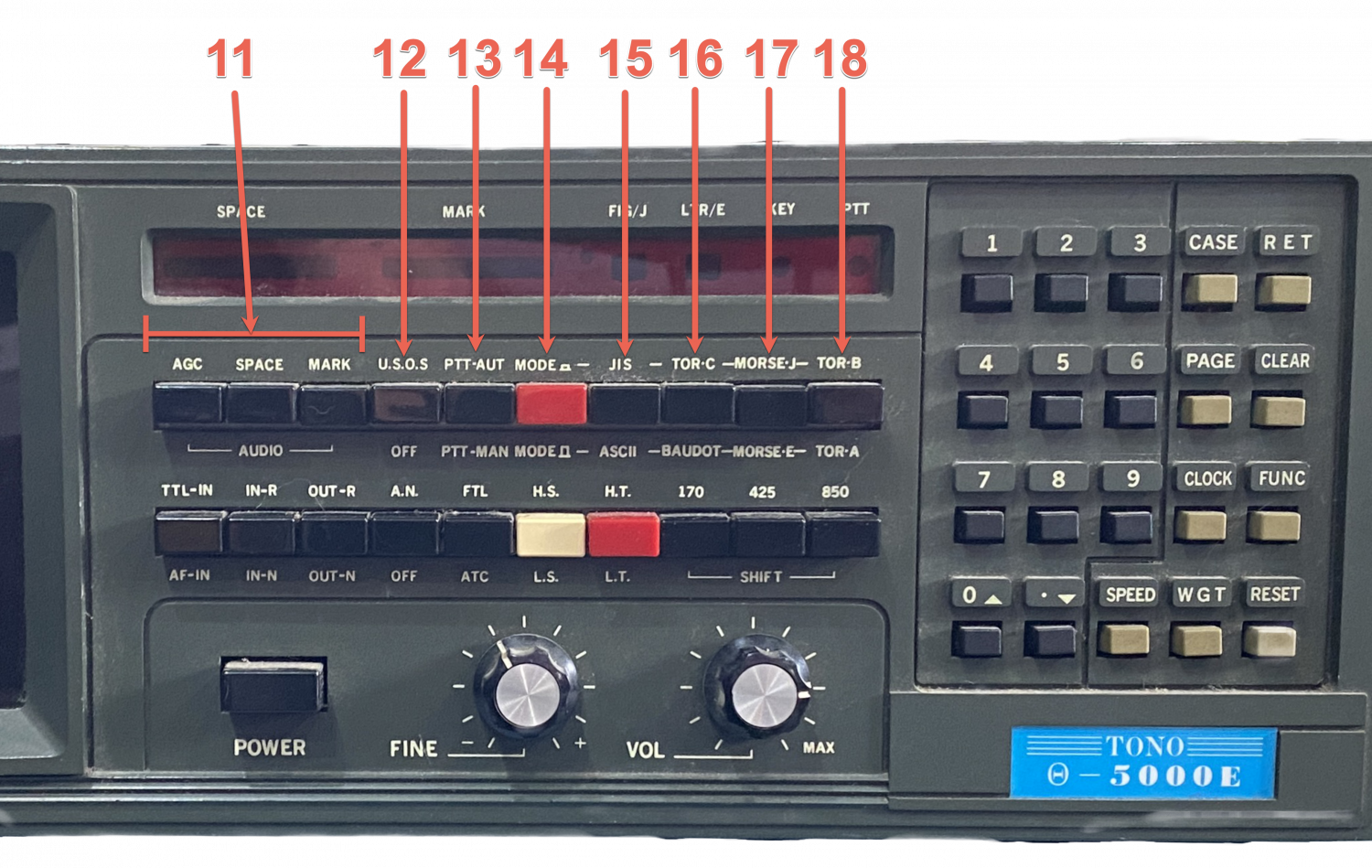
11 AUDIO Button
Selects the audio signal sent to the speaker.
AGC Button – monitors all incoming audio.
SPACE Button – monitors output of the space filter.
MARK Button – monitors output of the mark filter.
12 U.S.O.S.Button
Controls the UNSHIFT-ON-SPACE feature (ON/OFF).
13 PTT Button
Selects MANUAL or AUTOMATIC keying of the PTT line. In the automatic mode, the PTT line activates the transceiver upon presence of characters to transmit (KOX – Keyboard Operated Transmit). In the manual mode it is necessary to press “SHIFT-TAB” in order to key the transceiver PTT line. Another “SHIFT-TAB” returns the unit to receive.
14 MODE Button
Effects upper selection of the mode instruction buttons 15 18.
15 JIS / ASCII Button
Selects JIS mode (Japanese 8-bit RTTY) or ASCII mode. To select JIS mode MODE button (14) should also be pressed.
16 TOR-C / BAUDOT Button
Selects AMTOR modes (A, B or L) in the RTTY system or BAUDOT mode (5-bit RTTY). To select AMTOR modes in the RTTY system MODE button should also be pressed. In this event, the RTTY modem can be used for the AMTOR modes.
17 MORSE-J / MORSE-E Button
Selects Japanese CW mode or European CW mode. To select Japanese CW mode MODE button should also be pressed.
18 TOR-B / TOR-A Button
Selects AMTOR modes used in the CCIR system.
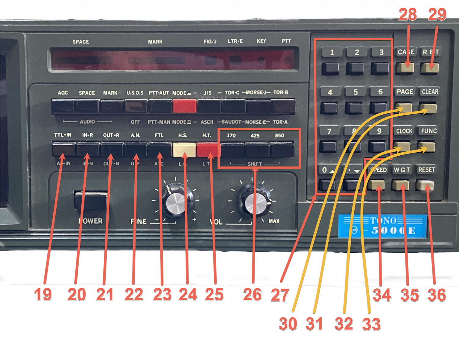
19 TTL IN / AF IN Button
Selects input terminal. With TTL IN selected, input is accepted from an external device connected to the INPUT TTL terminal. With AF IN selected, input is accepted from an external device connected to the INPUT AF terminal.
20 IN-R / IN-N Button
Reverses / Normalizes the polarity of incoming signals.
21 OUT-R / OUT-N Button
Reverses / Normalizes the polarity of transmitting signals.
22 A. N. Button
Controls the ANTI–NOISE feature.
23 FTL / ATC Button
Selects FTL (Fixed Threshold Level) or ATC (Automatic Threshold Control). ATC is usually selected.
24 H.S. / L.S. Button
Selects High Speed modem or Low Speed Modem in the RTTY modes (Baudot, ASCII).
25 H.T. / L.T. Button
RITY modes ( Baudot, ASCII ) Selects 2125Hz or 1275Hz mark tone. H. T. stands for High Tone (2125 Hz) and L.T. for Low Tone (1275 Hz). CW autotracks higher speed RX signals (above 50 WPM)
26 SHIFT Button
Selects shift width of 170Hz, 425Hz or 850Hz.
27 Number Push Buttons
Numbers for ‘Command Entries’ such as Speed or Weight setting.
28 CASE Buttons
In receiving, Selects the alternate “Letters” or “Figures” character set in the RITY modes, or between Japanese and European Morse Codes in the Japanese CW mode.
29 RET Button
Performs CR and LF on the screen and outputs CR / LF signal to printer.
30 PAGE Button
Switches the display between available two pages, Page l and Page 2. Page l is displayed in the initial state.
31 CLEAR Button
Clears the buffer, Page 1 and Page 2.
32 CLOCK Button
Faciliates Time / Date Set or Timer transmission setting.
33 FUNC Button
Keys FUNCTION instruction entries.
34 SPEED Button
for the speed setting entries.
35 WGT Button
For the Weight setting entries. (along with any number 0 through 9)
36 RESET Button
Initialize the microprocessor and clears the buffer, Page 1 and keyboard options. The channel memories and Page 2 are not cleared. It is recommended the RESET be pressed whenever changing modes.
It has been ages since I last used this with the Drakes and I can never remember it being this difficult so to anyone new to one of these, don’t get too scared, I remember it being fun, especially in a pileup.
There is too much to put on one single post on this website, So I will Post more pages under the ‘HAM RADIO’ menu when I get time.
Last Time Updated – 26th July 2023

