In last month’s LAB NOTES’ episode, I described the properties of an interesting twin-lead resonant structure that formed a loop made with both inductive and capacitive loading to shorten the length of twin-lead required. I am sorry to say that, after about 4 hours of calling and answering CQs with the loop spread out both horizontally and vertically, it evidently doesn’t radiate. It’s yet another resonant structure that contributes to the QRP revolution—all transmitters connected to it become QRP transmitters!
Tesla’s Influence Continues
All of the capacitive antennas, such as the Isotron and EH antenna, use a Tesla-coil-like inductor to resonate the low capacity of the “antenna” at some frequency. In these experiments, the constructor often observes that this coil always resonates correctly if it is made with a magic length of wire, such as 1/4 wavelength or 1/8 wavelength. For this month, I have investigated this assertion by measuring the behavior of a coil as it is unwound a turn at a time and the wire stretched out into an antenna.
I found that the resonant modes, where the open end of the coil or wire is transformed into low impedance that nears the 50-ohm impedance of the antenna analyzer, behave in two different ways as the coil is unwound. The lowest resonant frequency changes from the frequency where the wire is near a quarter wavelength long to a much lower frequency, where the total wire length is 0.16 of a wavelength long, and then rises to a higher frequency again where the stretched-out wire is 0.313 wavelengths long. This behavior is associated with the whole structure, and the resonant frequency changes when the coil or the analyzer is touched. It is tricky to tune, as the knob must be turned a bit and the hand withdrawn to see the result. At the lowest frequency, 14.53 meters of wire with 3.2 meters stretched out tuned to 3.4 MHz! This suggests that a loaded 80-meter dipole antenna might be made with a coil and only 6.4 meters assembled length.
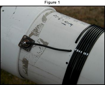
Unwinding the Coils in Capacitive Antennas - Figure 1
All the other resonant frequencies change smoothly from the lowest frequency associated with the full coil to higher frequencies associated with the shrinking coil. Touching the system doesn’t change the resonant frequency when the coil is large. Due to the high inductance, little energy seems to get to the end of the coil. There appear to be preferred modes here, because new resonant frequencies appear starting at the same value and then rising as the coil shrinks.
The experiment was arranged by soldering a connector to the end of an arbitrarily chosen 14.5-meter length of insulated, stranded electrical hook up wire. Two holes that would pass the wire were drilled about an inch apart around the circumference of a piece of 6-inch PVC pipe. I threaded the wire through the holes so that it came out of the pipe and was then wound onto the pipe to form a 28-turn coil with a turn density of 7 turns in 0.75 inches. The end of the wire was fixed to an insulator and temporarily taped onto the pipe. Figure 1 shows a close up of the coil construction.
A pulley was rigged about 50 feet away from the test position, and a 100-foot string was run around the pulley with both ends of the string stretched back to the test position. One end of the string was tied to a pole and the other end tied to the insulator and coil.
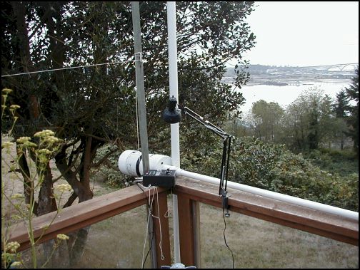
The PVC pipe was actually the case around the tuner of a previous experiment, and came with two caps. One cap had about 6 feet of 2-inch pipe mounted in the center. When assembled, the coil had a 6-foot pipe “tail” with a hexagonal pipe flange at the coil end. The whole assembly was placed along the railing of the house deck with the coil sticking out over a corner. Figure 2 shows the overall view of the test site.
Unwinding the Coils in Capacitive Antennas - Figure 2
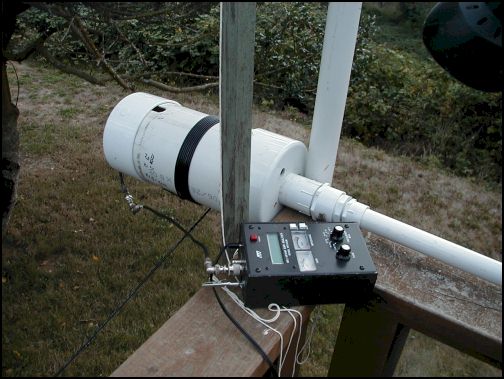
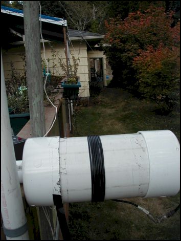
The coil could be rotated to wind or unwind the coil while the “tail” kept the whole thing from coming off the railing. The hex flange indexed the coil rotation to the same position as each turn was removed. The experiment proceeded by pulling the wire out using the string and pulley while the coil was unwound one turn, then the string was tied off and the analyzer connected. The various resonant frequencies were recorded. Then the analyzer cable disconnected (so the coil could rotate). The procedure was repeated until the coil was completely unwound. Figure 3 shows a closer view of the components. Figure 4 looks down the wire length from the coil to the pulley.
Unwinding the Coils in Capacitive Antennas - Figure 3
Unwinding the Coils in Capacitive Antennas - Figure 4
Table 1 shows the physical dimensions of the components.
Unwinding the Coils in Capacitive Antennas - Table 1
Table 2 shows the electrical properties associated with each coil condition.
Unwinding the Coils in Capacitive Antennas - Table 2
The first column is the number of turns on the coil. The next 3 columns give the unwound and extended wire length in inches, meters, and wavelengths at the lowest resonant frequency. The yellow columns give the lowest resonant frequency and its wavelength; the rust color label indicates the lowest frequency obtained. The green column gives the total wire length in wavelengths at the frequency indicated. The last two columns give the calculated coil inductance using the formula:
This formula becomes inaccurate if the length/diameter ratio is less than 0.3. This factor contributes to the variations in the data for the situation where the coil contains only a few turns. The last column is the capacitance to resonate the computed coil inductance at the resonant frequency that was measured.
Table 3 shows the data in the regime where the coil is large and the extended wire is small. Note the significant difference in behavior between the yellow column, (the quarter wave transformer case) and the other columns, which show modes evidently associated only with the coil.
Unwinding the Coils in Capacitive Antennas - Table 3
Table 4 shows the transition region where the extended wire is beginning to be long enough to have modes within the frequency range of the data. The colored columns are extensions of the modes found in Table 3, but new values are appearing due to the wire modes.
Unwinding the Coils in Capacitive Antennas - Table 4
Table 5 shows the predominately wire determined modes. Note that the ‘turns’ data are the columns in Table 5. This is because of the large number of extra frequencies that exceeds the number of columns available. Each row is a representation of the same mode as it changes due to the wire length and inductance. The colors correspond to the same sequences as in the other tables: yellow is the fundamental or lowest frequency mode. In Table 5, one sees that the lowest frequency mode shifts upward in frequency twice as the last turns are removed, leading to a split mode for the lowest number of turns. I’m not sure why this happens.
Unwinding the Coils in Capacitive Antennas - Table 5
The conclusion is that the 1/4 and 1/8 wavelength values are good starting choices for the wire length to wind the coils for capacitive antennas. The tuning or capacitive component of the antenna will determine whether it is operating with the maximum shrinkage associated with the lowest frequency 1/8 wavelength mode. Since the modes at higher frequencies seem to be contained within the coil, as evidenced by their tuning stability when touched, I doubt that these modes radiate. Therefore, multi-band versions of this antenna do not seem likely to me. Many of these resonances are not very near the 50-ohm Zo of the analyzer, and my analyzer does not indicate the sign of the reactance part. Tuning a loaded monopole may require additional component–L or C–to get a low SWR.
The next step in this experiment will be to make two loaded antennas at the lowest frequency, maximum shrinkage configuration and to connect them in the form of a dipole. The immediate question that occurs to me is this: should the coils be allowed to couple together, as if they were wound on the same form in the same direction? The loaded dipole would provide modest antenna shrinkage, but again, will it radiate?
Originally posted on the AntennaX Online Magazine by Joel C. Hungerford, KB1EGI