20 Meter Half Wave Vertical Antenna
The vertical antenna has been alternately condemned and blessed depending on who you listen to. “Radiates poorly in all directions,” “best antenna for receiving noise there is,” and “makes a good lightning rod.” The condemning goes on and on. On the other side of the fence, my personal experience has been that the vertical antenna does the job well enough for those who were willing to install the antenna correctly. This means that for a 1/4 wave antenna, radials must be installed which a lot of people do not want to do.
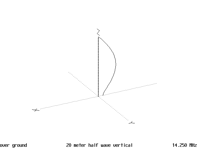
So, let’s use a vertical that does not require radials. The half wave vertical does not need any radials at all and is, generally speaking, more efficient than a 1/4 wave vertical. This is because the major current node on the half wave antenna is in the middle of the antenna and therefore 1/4 wave above ground. This eliminates ground losses present with a 1/4 wave vertical since the major current node is at the feed point which is at ground level.
So, let’s use a vertical that does not require radials. The half wave vertical does not need any radials at all and is, generally speaking, more efficient than a 1/4 wave vertical. This is because the major current node on the half wave antenna is in the middle of the antenna and therefore 1/4 wave above ground. This eliminates ground losses present with a 1/4 wave vertical since the major current node is at the feed point which is at ground level.
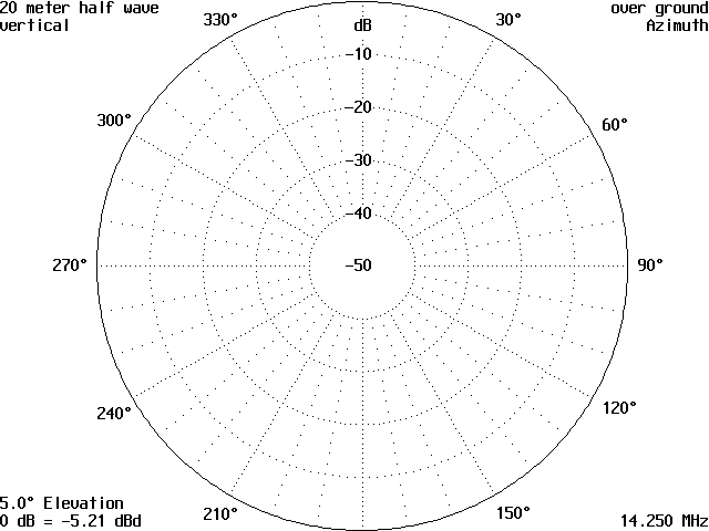
The gain figures on the diagram are misleading as the angle of radiation puts the maximum signal at a lower angle. This is where the signal needs to be, because the lower the angle of maximum radiation the further out your signal will go before it first hits the ionosphere. This means the signal will then come down to the ground further out, hit at a shallow angle, then bounce back to the ionosphere at a corresponding shallow angle. Thus, your signal will be reflected between the ionosphere and the earth fewer times to travel a given distance. Also, each bounce on either the earth or the ionosphere absorbs a little of your transmitted signal, so it is important to keep the bounces to a minimum.
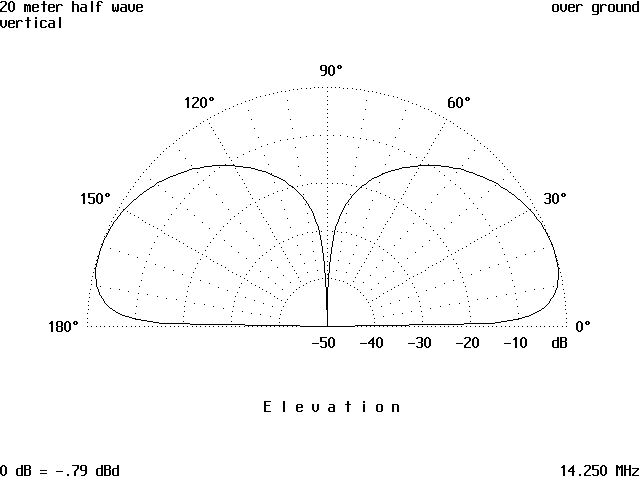
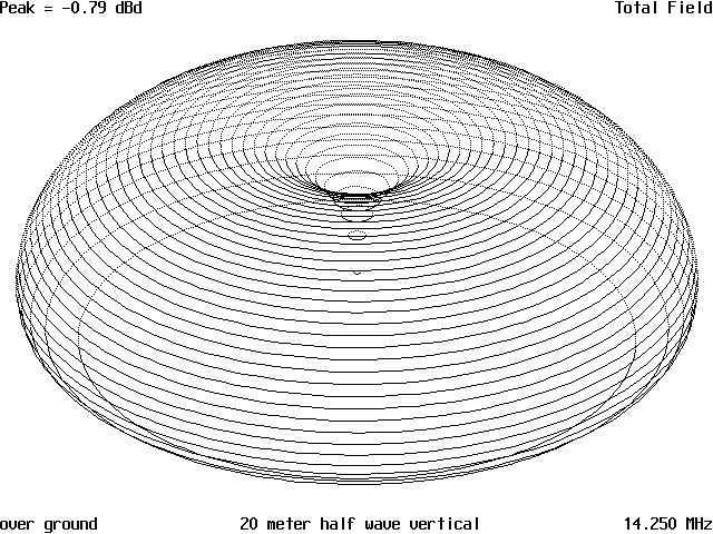
If an antenna has a lot of gain, but a high angle of radiation, all the transmitted energy will be dissipated rather quickly in the earth and the ionosphere, leaving none for the DX station to hear. This is why the angle of radiation of an antenna is so important if working DX. Also, it is why the half wave vertical is a good DX antenna. In Figure 3 the vertical pattern is displayed and shows the lower angle of radiation. Figure 4 is the 3D display of the pattern and which shows the null directly overhead of the antenna as well as the signal level increase as the pattern approaches the horizon.
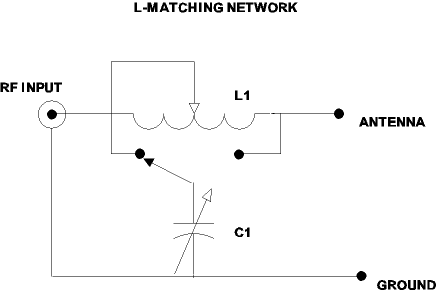
Since the antenna is 1/2 wavelength long and the feed point is at the end, this is a high impedance feed point and some sort of matching system is needed to match the antenna to the feedline. Figure 20-5 is of an L tuning network that will do the job well. It has the capability of matching a lot of impedance, both high and low. The values are not listed, as this will depend on what you are able to find and use. The coil could be wound on a PVC form and tapped until the SWR is as low as you can get it. The variable capacitor should be around 500pf or higher and can be made up by using a combination of a variable and several fixed capacitors. After you get the SWR down, you can then make a matching network using fixed components and then use the variable network for other antennas.
If the antenna is made of TV mast sections or galvanized downspout, either solder or weld the sections together. This will eliminate corroded joints and resultant TVI and other problems that corrosion causes. For that matter, all connections should be soldered. A ground rod will be needed to tie the shield of the coax feed line to ground. Also, you should install a RF choke to ground to drain static off the antenna. This will help keep high voltages from building up on the antenna and possibly damaging your rig. It will also help prevent lightning from striking the antenna.
Last, install some sort of fence around the antenna to keep people and animals from contacting the antenna. This needs to be made from non-conducting material to not cause tuning problems. This will keep you out of trouble because if anyone gets burned on your antenna, you could end up in court and be in deep trouble quick.
Originally posted on the AntennaX Online Magazine by Richard Morrow, K5CNF
Last Updated : 24th February 2024
