Portable 440MHz Yagi
Unusual Design
The antenna design is rather strange looking as the elements are not what most people are used to seeing. This antenna was designed to transmit on a very narrow range of frequencies. Since I had the thrilling experience of operating during a hurricane, I know what happens to most antennas. They blow away. There is one repeater here locally that, due to its location, will very possibly survive. So it was for this repeater that this antenna was designed, although it will hit the others that are in this area with my HT running 2.5 watts.

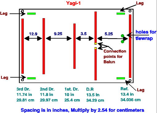
Figure 1 shows the unusual design of this antenna. The unusual design of the antenna is apparent immediately as the unusual element lengths can be seen. These lengths were derived after considerable time was spent running my CAD program working towards a design to gave a high F/B ratio, moderate gain, easily stowed and set up. Pattern was not too important to me, as the distances are not too great and the terrain is flat. But for some directivity is desired if you have to reach over greater distances, or to an emergency repeater antenna that may not be as high as the original.
Copper Tape Antenna
It was during this planning stage I happened to see something in an old magazine that caught my eye. This particular article was about building an antenna out of copper tape, and the author said that he got his tape from a store that sold stained glass materials. After searching the local hobby stores I found rolls of copper tape of various widths and bought a roll of 1/4-inch (.635) tape, 35 yards long, (32 meters) for slightly more than $7 US. There were other widths, but I felt this was good enough for my needs. Next, I found a sheet of rather grubby plastic and cleaned it, since it was the correct size required. I cut the tape to the proper lengths, did the spacing measurements and then stuck each element to the plastic sheet. It is easier to use some type of sharp tool to scratch the lines in the plastic to mark the location of each element on the plastic sheet than using a pen or pencil to mark the plastic.
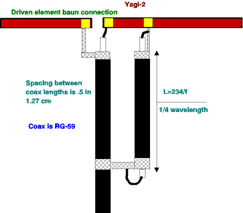
The impedance of the antenna turned out to be between 50 and 72 ohms, 65.9+j101 to be exact, and so a balun is needed to match the antenna to the feedline. At this point the ARRL antenna book was consulted and the balun was constructed out of RG-59. I know this is not correct to properly match the feedline, but the match was closer than if I had tried to match to the 50 ohm RG-58. In reality, the SWR isn’t enough to bother my HTX-404, so don’t worry about it. As far as power handling is concerned, any power that a mobile can put out should be no problem. I would hesitate to run more than 50 watts to this antenna.

Does it Work?
Does it work? Yes indeed! The configuration is such that the antenna can be hung vertically or horizontally, as there are small holes drilled in the corners. The side the feedline is mounted to has legs so it can be placed on a non-conducting surface and used horizontally.
After the photos were taken, some Velcro strips were added to allow the coax and PVC legs to be fastened to the plastic panel for transport. If you take the time to find the center of balance of the antenna, you can put the Velcro where the antenna could be fastened to a pole and rotated. This will give vertical polarization which repeaters use anyhow. Some method must be used to keep the antenna from sliding down the pole—like a clothespin. Not very sophisticated I suppose. Also, a tie wrap was added to keep the coax and coax balun from being pulled off of the plastic. The coax balun was glued in place with low temp hot glue, but any other method may be used that will not damage the coax. The tape can be soldered to with ease, but soldering should be done quickly to avoid damaging the plastic.
Less Than 1 Watt!
On-the-air testing showed, at the height of five feet, the repeaters I could hit were either full quieting or nearly full quieting. As far as pattern is concerned, this antenna has one. That is all I am going to say about that, as we are not chasing DX, but doing communications under an emergency situation or just maintaining contact while at work or something of this sort. The pattern will change some depending on the polarization, height and surroundings. The important thing is that, with less than 1 watt of power inside a building with many computers running and surrounding metal filing cabinets, I was able to access the repeater I wanted. Compared to the whip on the HTX, the interference from the computers was almost gone. The only computer heard was one in front of the beam about 25 feet away. The repeater is about 5 miles away, but some of the others I brought up were farther—16 miles was the farthest.
This antenna was not built for beauty, but utility.
Originally posted on the AntennaX Online Magazine by Richard Morrow, K5CNF
Last Updated : 25th April 2024
