Coil Winding - When you Can't Buy One
So a trip to a building supply resulted in the purchase of several feet of #6 bare ground wire as it was called. Then a coil form of 2 inch PVC was cut to the length I needed with a hole drilled in each end for the coil ends to go through to keep the coil in place while winding. An easy way to find the correct size drill is to take the wire you will use and poke it into your drill holder and adjust until it grips the wire. That is the size of drill needed for the following steps. The drill can be slightly larger than the wire.
The hard part, is to wind the coil while maintaining the correct spacing. Since the wire is rather large, it is not easy to wind the coil by hand and maintain the correct spacing. So, I came up with a spacing method that worked quite well. This illustration on the left shows my home-made device. As you can see, the coil turn spacer is a length of plastic that has the correct size holes drilled in it, then cut in half. Of course, you can use any other kind of material you may have on hand.
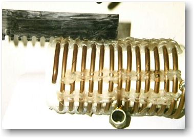
he next step can be seen in this photo. As you can see, the spacer is then used to line up the turns and then a hot glue gun was used to hold the turns in place. DO NOT REMOVE the spacer until the glue sets. Then you can continue around the coil and use the spacer to hold the remainder of the coil in place while you glue them in place. Just don’t move the spacer until the glue sets up good and firm.
Despite my best efforts, all of the turns did not maintain the correct spacing, but it was good enough for this particular application. In the photos, the taps that were made for impedance matching are indicated by the large banana plugs. The banana plugs and jacks are of the jumbo variety in order to handle the current that would be found in the antenna system. The entire coil was part of the home-made mobile kW antenna I built and designed to be plugged into the mast and ground connection on the ball mount.
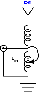
Figure 3 shows the diagram of the antenna as it was installed. Unfortunately, before I could get the linear I wanted, the car ate its engine and that project ended before anything else could be done. The information obtained from this showed that the external matching coil increased the radiated signal as determined by comparison with stations 300 miles away. At their location, the received signal jumped from S-9 to 20 over 9 when the coil was used. This signal level difference was apparent at more than one location. This was on 40 meters in the daytime. Power level was 65 watts as measured on a Bird 43 wattmeter. VSWR was 1:1 and bandwidth increased from 40 kHz to 65 kHz between 2:1 points.
The 75 meter signal increase was approximately the same, and the end results were worth the effort of winding that stiff wire on that small coil form. The bandwidth went to 23 kHz from 13kHz between 2:1 points. It also was noted that the increased power into the antenna caused the coils to get hot to the touch after about 30 seconds of carrier.
More Winding Info
Of course, there are other methods of coil winding and in the last few months there are some variations on winding coils at home as described by CQ Magazine for January 1998 and another method is found in the August, 1997 QST. Between all of these methods, one or more of them may give you an idea that best suits your needs on coil winding.
Originally posted on the AntennaX Online Magazine by Richard Morrow, K5CNF
Last Updated : 29th April 2024