Screwdriver Antenna
Editor’s Note: We are pleased to announce that antenneX and Ron Nott’s company, Nott, Ltd., have recently joined forces. antenneX is now an authorized distributor of the products manufactured by Ron’s company. The subject of this article, the Broadbander BB3 is one of those product lines. Be sure to visit the Shopping Shack at this web site.
Both air and vacuum variable capacitors have been tuned by this method. More ingenious are variable inductors, ranging from edge-wound coils with rollers to pancake spirals with sliding shorting blocks between turns. Internal and external tuners in amateur HF transceivers use small DC motors to tune capacitors in a tee network. Tuning an antenna, either directly or conjugately, by a motorized tuner is a technology that has been around for a long time.
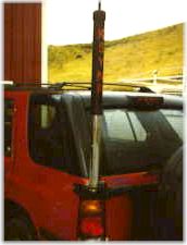
In 1991, Don Johnson, W6AAQ, was experimenting with directly tuning a HF mobile antenna when Ben Herr, WB6MNX, pointed out the fact that an electric screwdriver would make a good drive mechanism for such an antenna. Don recognized this immediately and designed a mobile antenna that used a modified electric screwdriver motor mounted inside the lower part of the antenna. This required that the lower part of the antenna be constructed of large diameter tubing which, while it may appear somewhat ungainly, greatly enhances the radiation efficiency of the antenna. More on this later. Now let’s take a look at the construction of a screwdriver antenna.
The thin-wall tubing may be either aluminum or copper. The BB3 antenna, manufactured by Nott Ltd., now available in the Shopping Shack at this web site, uses copper which is 2.125″ (5.4 cm) 0D with a wall thickness of .040″ (.10 cm). A Black & Decker screwdriver is modified to slip inside near the bottom end. A coil is wound of tinned #16 copper wire on grooved 1-1/2″ (3.8 cm) PVC pipe with 8 turns per inch (2.54 cm) and a total length of about 19″ (48.3 cm). This is enough inductance to tune the antenna from near 3 MHz to near 30 MHz on a typical mobile installation.
The screwdriver has a length of 1/4″ all-thread rod attached to it, which drives the coil up or down via a threaded metal disk in the bottom end of the coil. For contact between the copper tube and the coil, beryllium copper finger stock is soldered into the top end of the tube, so as the coil emerges from the tube (being driven by the screwdriver), it has a very low resistance contact of large area for minimal contact loss.
An aluminum disk in the top of the coil is threaded 3/8 “-24 female which is the standard thread for antenna whips. Either a stainless steel or quality fiberglass whip may be screwed into the disk.
Note that the only active portion of the coil at any time is the amount above the finger stock on the tube. The rest is completely shielded inside the copper tube, so it has no circulating current in it, as would an exposed coil with shorted turns. This further contributes to the antenna efficiency.
The coil is enclosed in a PVC weather cover, which protects it from weather, dirt, insects, etc. This cover moves up and down with the coil as it is tuned. Bear in mind, as this antenna gets taller, it lowers the operating frequency. Operating in a parking garage sometimes requires that it be run all the way down to the 10 meter position.
Impedance Matching
When an antenna is only 10 to 12 feet tall on 80 meters, the input resistance is very low. As Richard, K5CNF, has pointed out in previous issues of antenneX, the true radiation resistance is in the ballpark of 0.5 ohms. A point very important to remember, is that there is no instrument or device that can separate radiation resistance from loss resistance. They all give you a value, which is referred to as antenna input resistance-the sum of the radiation and loss resistance. When designing an impedance matching device, the antenna input resistance is the number you must use.
Included with a BB3 antenna is a toroidal transmission line transformer which has evolved through experience and the study of books by Jerry Sevick, W2FMI. On the lower frequencies, it functions as a transformer. But, at higher frequencies, RF energy couples through it capacitively until on 10 meters, where it pretty much couples straight through. The main result is that it works very well in matching 50-ohm coax to the antenna.
Whip length also gets into the impedance matching act as it provides the top loading which reflects back to the antenna input. For 80 meters, a 96 or 102 inch (2.4 or 2.6 m) whip works best in most applications. From 20 meters up, a whip as short as 63″ (1.6 m) works quite well and still allows operation in the upper end of the 75 meter band.
Features
Two features stand out if you have ever operated HF mobile with a conventional antenna. The first is convenience. As you cruise down the highway on a trip, there will be times when you will want to QSY or change bands. On older antennas, this means you must stop the vehicle, get out and either swap resonators or change taps on a coil. At night, in bad weather or in heavy traffic, this can be an unpleasant experience. A screwdriver antenna, such as the BB3, is remotely tuned from the driver’s seat at highway speed using only your SWR meter. There is a remote control unit with a reversing switch and a push-button for this function. Going from 75 to 10 meters requires only a bit more than one minute. Going between other bands requires even less.
The second feature becomes apparent if you wish to operate on MARS, CAP or any other frequency outside the ham bands, because the BB3 is continuously tuned covering ALL frequencies between 3 and 30 MHz. This allows you to meet a net or other schedule by simply pushing a button to retune the antenna.
Radiation Efficiency
In shootouts of HF mobile antennas, the BB3 is usually near the top, often beating big commercial names by 7 to 10 dB. How come? They’re about the same height and not as ugly. Recall that true radiation resistance on an 80 meter mobile antenna is a fraction of an ohm (from 0.3 to 0.6 ohms depending on overall height). The highest current point on an antenna is just above the base. Skin effect causes most of the RF current to flow in a very thin outer layer of the bottom portion of the antenna. If the bottom portion is stainless steel rod of small diameter, it can be viewed as a leaky resistor.
On the other hand, if the bottom portion is made of copper tubing of 2.125″ (5.4 cm) diameter, the area is much larger and the material (copper) is much more conductive. If you were to roll this tube out flat, it would become a copper sheet about 6-5/8″ (16.9 cm) wide. Which do you think has the greater value of resistance losses at RF? Obviously, the thin stainless steel rod.
Next, look at the coil. It is wound of #16 tinned copper wire to a diameter of 1-7/8″ (4.8 cm) and with 8 turns per inch (2.54 cm). Different pitches have been tried, but this coil geometry has proven to be the best overall. Again, as the coil emerges from the upper end of the 2-1/8″ (5.4 cm) copper tube, it is completely surrounded and in contact with copper beryllium finger stock to minimize loss resistance at the point of contact. Don’t forget that the unused portion of the coil is down inside the copper tube and completely out of the picture. Shorted turns in an exposed coil have high values of RF current in them due to autotransformer action. This current then wastes RF energy in the form of heat.
The disk in the top end of the coil is heavy aluminum. The top end of the coil attaches to it and then the top whip screws into a female 3/8″-24 thread. At this point, RF current is greatly reduced from what it is at the bottom end of the copper tubing, which is the drive point of the antenna.
Top Loading
Normally, a standard whip (stainless steel or fiberglass) is installed as mentioned, but many variations are in service as well. The BB3 with a 102″ (2.6 m) whip can be a real tree-whipper and bridge-banger. However, many are in use by long haul truckers who must keep overall height to no more than 13′-6″ (4.1 m), but have difficulty in finding a low antenna mounting location. They have built variations of an inverted L, a “pickle fork” top loading device and other inventions. All that is necessary is enough top loading to cause a significant flow of RF current through the coil to allow it to resonate the antenna. Obviously, a larger whip helps the lower frequencies.
To Sum Up
The screwdriver antenna has two big advantages over conventional commercial antennas:
1. Operating convenience
All tuning is done with a push-button from the driver’s seat at highway speed. No stopping the car, getting out, changing resonators, fiddling with coil taps or adjusting stingers in the top of the antenna.
2. High radiation efficiency
Where the RF current is the highest, the antenna is made of large diameter copper tubing. The coil is self-shielding and contact resistance is minimal. There is no vertical, air-cooled dummy load effect due to stainless steel construction-
Appendix – HF Mobile Antennas
Back in the 60s, I worked for Collins Radio Co. in Dallas, Texas and was involved with impedance matching and directional antennas for broadcasting. I was also active on 75 meter mobile and used a Hustler antenna. It was difficult to get a low VSWR, and as the result of some RF bridge measurements and calculations, I realized that at resonance, the antenna resistance was still considerably lower than 50 ohms. To get a better match, I decided to use the inductance of the antenna along with a shunt capacitor at its input to form an L network. Finding a transmitting mica capacitor of the right value, I placed it from the base of the antenna to ground and then fiddled with the adjustable stinger atop the Hustler 80 meter resonator. The SWR came down to 1:1 and the antenna worked very well (considering the loss resistance).
I told Ike, K5JPY about this, so he decided to do the same. However, he did his better than mine. He drove an El Camino and had mounted his antenna on the back of the sloping cab. Inside, he mounted a broadcast variable capacitor at the feedpoint so that if he had a rise in SWR with a QSY, he just adjusted the capacitor for minimum SWR. It was really slick.
Using this info, bear in mind that if you have a screwdriver or any other type of HF mobile antenna and have matching problems, you can make the coil of the antenna one element of an L network and install a variable capacitor for the other. In most cases, this will provide a flat SWR.
I’ve been trying to get Icom to incorporate the BB3 into the auto tuner of one of their rigs such as the IC706, but so far I haven’t been able to convince them. This would provide the ultimate combination between transceiver and antenna in that the antenna would be automatically tuned and the radio would get a perfect load-maybe some day!
Is Broad Bandwidth Really Good?
For years, it was believed that the broader the bandwidth of an HF mobile antenna, the better the antenna is. However, if you think about it, the device with the broadest bandwidth of all is a good dummy load. Like it or not, a short, efficient antenna is inherently a high Q, narrow band device. However, the ease with which a screwdriver antenna is remotely tuned solves this problem.
I have used an AEA HF analyzer to look at the bandwidth of the screwdriver antenna on all bands from 10 through 80 meters. The HF analyzer does a VSWR sweep through a frequency range. On 10 meters, the screwdriver antenna is quite broadband, but as you work down in frequency, you see the bandwidth narrow as the electrical height of the antenna decreases. By the time you get to 80 meters, it is quite narrow because the loss resistance is low. You may recall that if you need to broadband a simple parallel RC circuit, you place a resistor across it. The lower the resistance value, the broader it gets. That’s how the big name antennas get broad bandwidth. They make sure their products have loss resistance. It works, but it can cost 10 dB or more in performance, both transmitting and receiving.
If you want a HF mobile antenna with best performance, convenience and efficiency, it has to be a bit homely, but you (and hopefully the XYL) will learn to love it after you have lived and operated with it for a while.
Originally posted on the AntennaX Online Magazine by Ron Nott, K5YNR
Last Updated : 25th April 2024