The ZL Special - A simple DX Antenna
The ZL Special is a phased array antenna and easy to build. It is light weight, which makes it a good candidate for a TV type rotor to turn. On the lower frequencies, the antenna can be made of wire and aimed in the desired direction and not rotated. The gain from one of these antennas averages about 9 dB gain at the vertical angle of maximum radiation. The basic configuration is that of two dipoles fed 180 degrees of phase and spaced according to a given formula. The rear dipole is longer than the front one and is 180 degrees out of phase with the front one where the coaxial feed is located. At a minimum height of ½ wavelength , in the case of the antenna I had on 10 meters, I was able to hear signals as close as 2000 miles, but that was the closest. However, the DX could be heard from all over the world, wherever I pointed the beam.
Figure 1 is the vertical plot of a ZL Special for 15 meters and it can be seen that the major lobe is at 15 degrees with 9.06 dB gain and a minor lobe at 49 degrees with about 7 dB gain. This is good enough to work some more DX as conditions change. Having more than one significant lobe in the vertical plane can be an advantage at times when the band is changing.
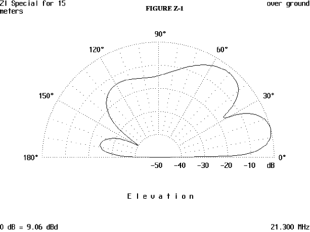
Figure 2 is the horizontal plot and it indicates a beam width of 60 degrees The front to back ratio is very good for this antenna and is about 23 dB down.
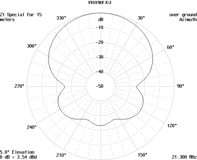
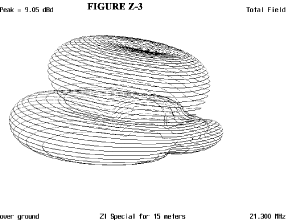
Figure 3 is the 3D pattern and shows the two lobes present to the front of the antenna. There is a rather deep null to the rear of the antenna that can be seen on the vertical plot and the 3D plot. This null is at 30 degrees vertical angle and is very deep down to -50 dB. The rather small minor lobe to the rear is very far down and indicates the very good front to back ratio this antenna has
In Figure 4, the basic frame can be seen. It can be made of wood, but not of metal, since both of the elements are hot and must be insulated from the mast. So the plumber’s delight construction is out. My particular beam was made using the stressed beam type of construction, where the elements were made of PVC and pulled into a bow by the elements of the antenna which were made of 300 ohm twin lead. This worked well for as long as I had it up. It was destroyed by a low flying high speed large bird. This method of construction will work well, and can be duplicated using bamboo, willow branches, or whatever you can find., as long as you do not use metallic spreaders. Another method is to tape or otherwise fasten wire to bamboo or long thin branches and use them as elements. You can also spiral wrap the wire around the supporting element. Just remember to spread the wire turns about one turn per foot (.3 meter). This will also work well, but varnish or paint the elements, as well as the basic frame. Protecting the basic frame from the weather and the elements, if you use natural materials, such as wood, for the elements is important.
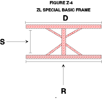
Figure 5 illustrates this type of construction, which is a very quick and easy method to construct your beam. Just be sure that you brace the front and rear elements to reduce the elements from flopping and waving in the wind. A brace between the two elements about midway out from the middle of the beam will keep the flopping around in the breeze. If you do not do this, the beam will flail its’ elements to death, and you will have to fix it.

Figure 6 shows the beam in finished form, with no frequency specific measurements. This is shown merely as a guide about how the beam may be constructed, but can be modified to fit whatever you may have on hand. After you have finished the beam, you need to find the balance point of the beam so as to determine where to put your mounting hardware. This is easily done by placing the beam on a support of some sort like the square back of a chair or sawhorse or other such device. Then move the beam back and forth on the support until the beam balances. Mark the cross member at the balanced point and then put your mounting hardware there. Now, connect the feed line and put up the antenna. The method of feeding the antenna is up to you. Coax feed is fine and so is the use of twin lead and an antenna coupler to tune out the VSWR.
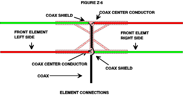
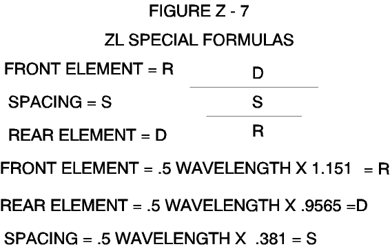
Now the only thing left to do is to design your antenna. Figure 7 is a table of the formulas to help design your antenna. The use of these antennas on the new WARC bands will put you on top of the pileups which occur on these new bands. There are not too many commercial beams made for these bands and anyone with a beam will be king of the hill when you get on the air.
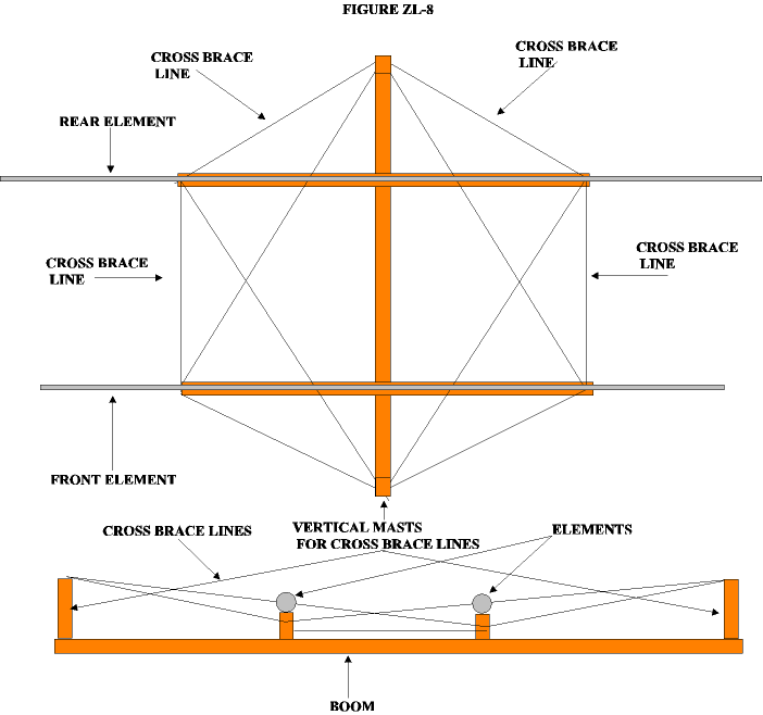
The last figure, Figure 8 is of the method of bracing a stressed beam type of antenna. The basic frame is also an alternative method of building a basic frame. The cross bracing with non-conducting lines is shown both from the top view and a side view. Depending on what you have to build an antenna with, you may need more lines or less. This is just shown as a example of one way to do the bracing.
Originally posted on the AntennaX Online Magazine by Richard Morrow, K5CNF
Last Updated : 16th March 2024
