ast month’s article attempted to explain that as it is accelerated charge which radiates, the contribution to the electric field at large distances is proportional to the time rate of change of (length times current). More radiation is produced by higher currents, by currents in a longer length of wire (provided it is short compared to a quarter-wavelength), or, for a given antenna structure, by increasing the time rate of change (by putting up the frequency).
In this and next month’s articles, suggestions are made which might enhance the performance of compact antennas. These involve lengthening the current-carrying parts of the antenna without enlarging the overall physical dimensions. Also, we can tune the antenna as was discussed in an earlier antenneX article (From The Shack-“Antennas with Area”) so that the current in the radiating structure is many times larger than that supplied by the feed.
Multi-Turn Loops
First, we consider multi-turn loops of small diameter. We shall restrict discussion to loops where the total length of wire, if stretched out in a straight line, is less than a half-wavelength. This ensures that the current direction around the perimeter does not reverse as we hypothetically travel along the wire.
Making a crude assumption that the current is constant along the wire, adjacent turns will be carrying the same current as each other, and for an N-turn antenna, the product of (current times little element of length) will be N times larger than for a single turn loop antenna having the same feed (wire) current and the same diameter of loop. The inductance of the multi-turn antenna (at low and medium frequencies) will be N^2 times that of the single loop. The contribution to radiated electric field strength will be N times larger than for a single turn, and therefore the radiated power will be N^2 times larger for a given current. Since the total radiated power must be equal to (Rrad I^2) we may immediately deduce that the radiation resistance Rrad is N^2 times larger than for a single turn. This is beginning to look hopeful.
Lets Go Back
So a digression is in order. Why is the radiation resistance of small single-turn loops so much less than that of a short monopole having the same wire length? Without doing the maths too thoroughly, we can see that the electric field produced by a little elemental length at one end of a diameter is cancelled (apart from a small phase shift) by the little element diametrically opposite. The loop is shown in Figure 1.
The Radiation Impedance of a Wire Antenna - Figure 1a
The Radiation Impedance of a Wire Antenna - Figure 1b
The small phase shift produced by the transit across the loop is crucial; without this phase shift there would be no radiation at all from small loop antennas. The amount of phase shift is (diameter/wavelength) times (2 pi) radians or times 360 degrees.
The Radiation Impedance of a Wire Antenna - Figure 2
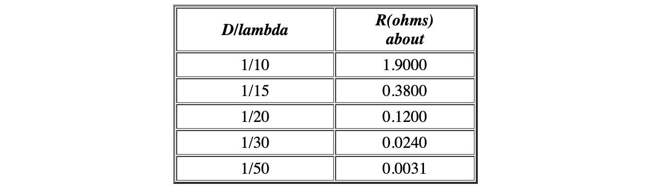
Thus the electric field contribution is smaller than from a straight wire by a factor of diameter/wavelength. As usual, the radiated power and therefore radiation resistance is proportional to the square of the electric field. We thus find that the radiation resistance of the loop antenna is smaller than that of a wire antenna of the same total wire length by a factor (diameter/wavelength)^2. Last month we saw that the radiation resistance of a short wire antenna goes as (length/wavelength)^2 and we produced a table of values. Therefore the radiation resistance of a small loop antenna goes as (diameter/wavelength)^4.
If we do the calculations carefully, and with the proviso that the current is constant around the loop, we find the following expression for radiation resistance of a small loop antenna of diameter D at a wavelength lambda.
Looking at Jack Belrose’s article in this month’s issue (see Compact Loops Re-Visited) on a typical compact loop for use at 3.852 MHz in the 80 metre band, we discover that the wavelength is 77.88 metres, the diameter 1.7 metres, D/lambda is 0.02183 (about 1/45) and the phase shift across the loop is theta = 0.1372 radians or 7.86 degrees. The formula we have quoted here predicts the Rrad radiation resistance to be 4.36 milliohms (0.00436 ohms) and indeed, Jack Belrose’s NEC simulation puts it at 4.356 milliohms, in very satisfactory agreement with the theory we have quoted above. He also predicts, for 32mm diameter aluminium tube, a loss resistance of 41.6 milliohms which is nearly 10 times larger than the radiation resistance. Thus, if we provide power to this single bare loop antenna, only about 10% of the transmitter power will be radiated and the rest will go to heating up the antenna structure.
The Radiation Impedance of a Wire Antenna - Figure 4
What can we do to improve this situation? If we increase the number of turns in the antenna, still keeping the total wire length less than a half wavelength (so that there is no reversal of current direction on the loop), the Rrad will rise (assuming uniform current) as the square N^2 of the number of turns N. However, the loss resistance will only rise as N since it is proportional to the total length of the wire. So we expect the efficiency of a multiple turn antenna to be larger, for the same wire or tube diameter. A confounding factor is that there will be capacitative coupling between adjacent turns of the antenna which will modify the current distribution.
For the example above, 4 turns of wire (N=4) gives us a Rrad of 16*4.36 milliohms or 70 milliohms, and a loss resistance of 4*41.6 milliohms or 166 milliohms. The efficiency is 70/(166+70) or 0.30 or 30% which is significantly better. The total wire length is 1.7*4*pi = 21.4 metres or 0.27 lambda which is acceptable.
Can we tune this antenna, and if so, how? Figure 4 compares the Jack Belrose tuning, with the capacitor opposite the feed, with a suggestion where the capacitor is across the feed-loop junction. In the former case, the loop wire current is just equal to that supplied by the feed (assuming constant current along the wire), whereas in the latter case the current is Q times larger where Q is the quality factor of the resonant circuit consisting of the loop antenna and the tuning capacitor.
Now, the radiation resistance of the antenna is proportional to the (wire current) squared, so by using a multi-turn loop antenna and tuning it at the feed we can make the feed-point resistance larger by a factor (NQ)^2 than the (Rr radiation + Rloss) total resistance of a single turn untuned loop. If we want a drive point resistive impedance of 50 ohms for our example above, we can engineer this if we know the total loop resistance, in this case 0.166 + 0.070 = 0.236 ohms by choosing Q = sqrt(50/0.0236) = 14.6. This does not seem an impossibly high Q and it may be adjusted by a tap on the tuning capacitor. We then find that the efficiency of this antenna remains at 30% and the bandwidth is 260 kHz in 3.852 MHz. The situation is summarised in Figure 5:
The Radiation Impedance of a Wire Antenna - Figure 5
We have designed (from first principles, with no cut-and-try experimentation) an antenna which is compact (1/45th wavelength across), has sensible driving point impedance and bandwidth, and a useful (if still not very good) efficiency. It is suggested that this is how the Isotron antenna Isotron Antennas – Main Page works. If any readers of antenneX would like to construct this design, try it out and write it up, we may learn whether the simple ideas presented in this article are in fact correct.
Jack Belrose is right to draw attention to the sensitivity of loop antennas to capacitative coupling between turns and to the current distribution along the wire. However, it may be that he takes an unneccesarily gloomy view of the prospects for small tuned multiple-turn loop antennas.
Originally posted on the AntennaX Online Magazine by Dr. David J. Jefferies