Restricted? Use a Discreet Antenna
Having established that an antenna should be invisible opens up a whole new realm of possibilities. For one thing, legitimate antenna designs can be used, although with some reservations. Unlike the Emperor’s new clothes though, the antennas really are there.
One of the first antennas I erected as a new Ham was a simple mono-band vertical. For no other reason that I had it on it on hand, I made the radiating element out of a length of 24 gauge magnet wire. The antenna worked fine and I only took it down to replace it with a dual-band version. It was hard enough to see when it was new, but as the enamel coating oxidized, it got to the point were I had to walk right up to the antenna to see if it was still up.
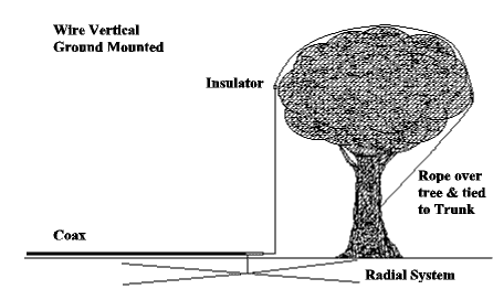
Antennas come and go, as tastes and interests change but as I became fascinated by the concept of a real antenna that could be used in the event of severe restrictions, with good results. Figure 1 shows my original wire vertical, which is suspended by a rope thrown over a tree. Such an antenna will obviously require a tall tree, but if you have one, and take the trouble to put on a decent radial system, it will work like a champion. 30 or 40 meters suit this system best, although you can use it on 80 if you have a tree of enough height. With a transmatch, however, you can tune it for use on other bands, but you wind up with most of your signal headed for the clouds if you use it more than one band higher in frequency for which it was cut. On the other hand if it is the best you can do, it will still give better results than no antenna at all. I was never able to load it up on 160 meters with my MFJ tuner, though.
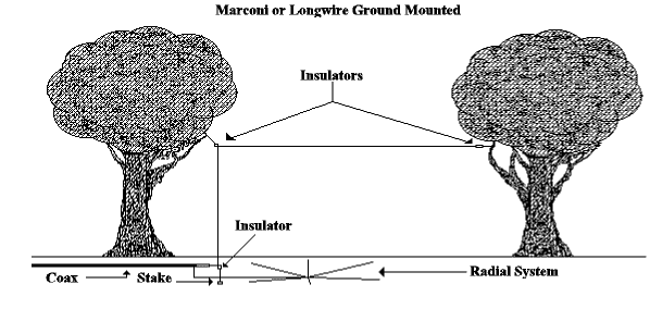
An antenna that will work on 160, if you make it long enough, is shown in Figure 2. It is a simple Marconi, which is merely an extension of the previous design. Instead of the antenna being completely vertical, this one has a long horizontal section. You really have two ways to go with this antenna. Either cut it for whatever frequency you are interested in, or run it until you run out of wire, or property, and call it a long wire. Unlike the previous antenna, this one will work well on the higher frequencies, if it is high enough and long enough. An advantage of a long wire antenna is the possibility of actually developing some amount of gain. For instance, if you can stretch the antenna for 129 feet, (four wavelengths on ten meters) you can realize three dB gain over a dipole.
Dipoles, undoubtedly the most common type of antenna, lend them selves to discrete construction rather well. The only limitation is that the thin magnet wire will not support the weight of a balun or coax choke and the length of unsupported cable that we normally dangle from a conventional constructed antenna. In most cases this drawback is easily overcome by connecting the center insulator (and the weight it supports) to a mechanical support such as a house, tree, or post rising out of the ground. Figure 3 shows three possible mounting schemes, for a dipole mounted to the gable end of a house.
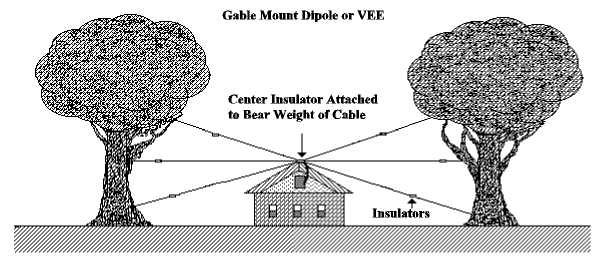
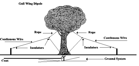
Figure 4 illustrates one way to construct a gull wing dipole, using a center insulator mounted onto a ground rod. In either of these cases it is advisable to cut the wire at least 5% long and prune for optimum SWR.
In the case of the ground mounted antennas described above, some means should be implemented to keep persons or pets from touching the wire while your rig is in the transmit mode due to the presence of high RF voltages which may exist. A small plastic garden fence or even a flowerbed surrounding the base will help ensure safe operation.
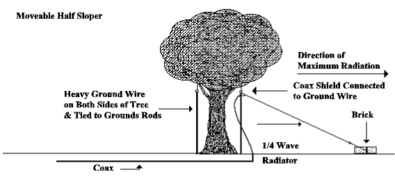
An antenna with a movable pattern is illustrated in Figure 5. Again, Because of the height of the tree involved, this antenna is probably best suited for 30 or 40 meters. In this case, the 1/4-wavelength radiating element is connected to an insulator mounted well up in a tree and a weight at the bottom is moved in the direction you are most interested in. the shield of the coax is connected to two pieces of heavy aluminum or copper ground wire, running one on either side of the tree, to the bottom where they are connected to a rod driven well into the ground. The lowest portion of the antenna should be above the point where it can be reached from the ground.
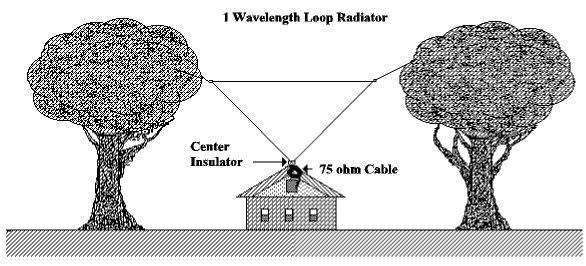
Loop antennas, a particular favorite of mine, are easy to construct and provide a couple dB gain with a relatively small distance between supports. Again you are limited only by your imagination as to what holds the antenna up. The loop itself can either be triangular, square or more likely some distorted shape required to fit the situation at hand. Try to keep the corner angles from being too severe, as this produces some amount of signal cancellation. Under ideal conditions, a square loop has an input impedance of 100W , which requires a transformation to properly match a modern transceiver. Fortunately, this is simply achieved by adding a length of 75W cable, connected in line with the antenna and the 50W cable. The length of this cable should be an electrical quarter wavelength rather than a physical 1/4-wave. This can be calculated by dividing 234 by the desired operating frequency and multiplying that figure by the velocity factor of the cable used. For an example, to transform the impedance of a full eave loop at 7.15 MHz to a usable 50 ohms, using a piece of RG-59 cable with a velocity factor of 75%, divide the frequency by 234 which results in a length of 32.7 feet. Multiply that length by .75, which comes to a required cable length of 24.5 feet. By the way, don’t splice the cable. Use the appropriate UHF connectors and weatherproof them properly. Again be sure to be generous within the length of the radiating element and cut it to resonance.
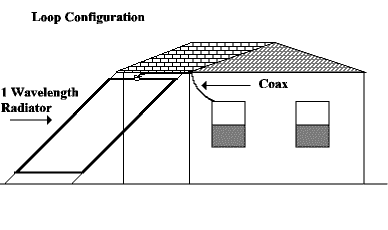
Figure 6-8 shows several possible loop configurations. Use your ingenuity to adapt a loop to suit your needs. It may not turn out in a recognizable geometric shape but the results will please you.

In keeping with the discrete antenna construction techniques illustrated above, several other things come to mind. Antenna cables should either be buried or concealed in some way, such as run up a gutter downspout. Cable running up a tree can be made to blend in with the bark by spraying it with gray and brown or olive drab paint. Cable runs up the side of the house can be painted to match. Obviously, insulators and supporting ropes for an antenna weighing two or three ounces need not be too hefty, either. Small pieces of clear plexiglass works well for center and end insulators. Nylon twine with a breaking strength of over four hundred pounds can be purchased at your local hardware store. I have dyed a whole roll of twine at a time by soaking the lot overnight in gray dye, which renders it just about as invisible as the antenna against pretty much any background.
In the same vein, in order to keep from attracting attention to yourself, use care to avoid TVI or interference with other electronic devices. To protect yourself against complaints of interference, keep your power to reasonable levels. QRO operation has a tendency to pop up in the most troublesome locations. Accurate logs showing not only contacts but unanswered calls can be used to prove to disgruntled neighbors that the problem they experienced must have come from some other source. Using your electronic ability to help them solve their dilemma will go a long way toward keeping peace in the community.
During the course of this article, I have tried to stress one basic idea. That is, just because you have to live with restrictions, even if they are self-imposed, doesn’t mean you can’t enjoy one of the most exciting of all avocations. I would not dream of encouraging any one to violate the law, but we have a legal right to an antenna as needed to communicate with other hams. However, it is much easier and cheaper, to live within our constraints than to fight City Hall. Antennas, as I have described above will certainly not attract attention to themselves, and if you operate carefully and with restraint, there is a good chance that your neighbors will never know you are a Ham.
Originally posted on the AntennaX Online Magazine by John R. Somers, KC3YB
Last Updated : 13th March 2024

