Impedance of Wide Regular Structures


Last month, I wrote an article that showed how to determine the self-capacitance of normal mode helical coils and used this value to determine the first resonance of the antenna. That article and recent exploration has rekindled my interest in treating antennas as lossy transmission lines and the desire to determine the impedance of wide structures.
The analysis of wide structures is particularly rigorous and involves either numerical techniques such as the Moment Method [reference 1 and reference 2] or integral equations such as those developed by Hallen [reference 2]. These techniques are rather involved and complex even when performed with the aid of a computer. There are, however, simpler techniques that can be employed to arrive at a ball-park solution.
The following collections of equations will enable you to develop a zero order approximation to the feedpoint impedance of regular structures, such as towers, cylinders and other lineal shapes (ones which have a length and effective radius). It will not enable you to determine the impedance of flat structures having no effective length, such as disks or plates nor will it be overly accurate.
Derivations of these techniques have been employed by broadcast engineers to determine such things as the top loading required to electrical lengthen monopole (tower) antennas.
The width of a structure affects the impedance and hence resonant length. The late Dr James L. Lawson [reference 3] has derived empirical equations, based on power series expansions, which described the reactance of a half-wave dipole for various wavelength to radius ratios.


or the more accurate equation:

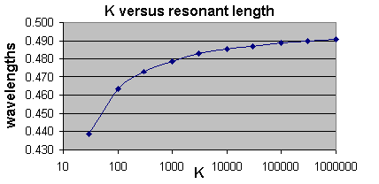
Lawson compares his empirical equations with results derived by Yagi to arrive at equations that have been used to determine the resonant length. These results are shown in Figure 1. The results show that the resonant length decreases as the structure becomes wider.


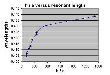
In reference 4 the authors compared the physical length of 1/4 wave resonant cylinders with various length to radius ratios. These hollow tubes were fed against a finite groundplane of 0.6 l formed by 64 wires elevated 0.15 l above the ground which means the antennas will probably not resonate at the same length when placed over an infinite groundplane.
(To compare figure 1 and figure 2 just divide the K by 4. From this you can see that the figure 2 resonant lengths are considerably shorter than expected.)
There are some important constants that are used throughout Electro Magnetic (EM) theory:


There are also some interesting relationships:


A radiating structure can be treated like a transmission line which has series resistance and inductance and parallel capacitance and conductance. If the structure is short it can be treated as though the characteristic impedance or Zo is constant. For quite short structures, those less than 1 / 20 th of a wavelength, the structure can be treated as though it has a real Zo because any series R and parallel G will be negligible. I have termed this real characteristic impedance Za and will reserve Zo for the complex impedance that we will cover later.

Za above is derived by Schelkunoff for thin biconical dipoles. When using regular structures which preserve their dimensions, Howe has determined that the characteristic impedance is more accurately reflected by equation (9).

In either case the approximation of Equation (6) yields:

Thus for a monopole, where h is the length, or for a dipole of half length h, the characteristic impedance of the section of length h is:

For structures of other shapes, the equivalent radius may be employed to derive the characteristic impedance:


Where s is the side of a square structure and w is the width of a lineal strip.
A conducting structure has capacitance. The capacitance per unit length of a structure (reference 5) is related to the speed of light and the characteristic impedance of vacuum by equation (7.3):

Thus the capacitance will be:

To a zero order, a structure can be treated as a transmission line with a constant Zo which is real (see Za from equations (8) to (11)). Equation (15) is derived from the open-circuited transmission-line equation (reference 7) when there are no losses and using the real Zo called Za.

Further if the structure is less than 1 / 20 th of wavelength, the impedance simply becomes that of equation 11 (because cot(x) = x for small x). See reference 5.

Alternatively for short structures, the feedpoint reactance can be obtained directly from the static capacitance:


Note when calculating the impedance of a dipole the results from equations (15), (16) or (17) must be doubled because there are two series sections acting as a transmission line. i.e.

You can use equation(15) or equations (16) and (17) for short wires or towers and get an idea of the feedpoint reactance that you will encounter! For example, a 9′ whip and base shows 35 pF of static capacitance – this constitutes a reactance of -2,492j ohms or 2,492 ohms of capacitive reactance at 1.825 MHz. If you were able to feed 100 watts into the base of this whip you would see 499 volts – so look out!
If you were to take a water tank 9′ high and 6′ wide its characteristic impedance from equation 8 would be 5.91 ohms and the capacitance from equation 4 would be 1,546.7 pF – does anyone have such a tank on their ranch? This would provide a feedpoint reactance of -56.4j at 1.825 MHz and this reactance would have 75 volts across it when it is fed with 100 watts of power!
However, it is likely that the whip and tank has real losses (radiation, resistance and conductance) so a real resistance would also be present in the input impedances, so the voltage may be different to these initial calculations.
If the structure length is significant compared with the wavelength and or has measurable losses, both series R and parallel G, then the structure is best described by:


Where C and L can be derived from the fundamental properties of the space surrounding the structure:


Because a monopole looks like a transmission line which radiates you can assign R from the following (assuming Rs is caused by copper):


The Rr equation becomes inaccurate once a quarter wave length has been exceeded which results in incorrect values for the transmission line propagation terms
The conductance term can be derived from the assumed Q. You may choose to set G to 0 as this term does not affect the location of resonance. Loss.cpp employs, where Q = 1000,
Which is quite high, you could use 500:

When the structure becomes wide the equations are not accurate, because first and second order effects have to be accounted for. Also, the capacitance exhibited by the ends of the structure, adversely disturb the results. The wider the structure, the more-pronounced the end-capacitance to ground. Even a hollow structure will have capacitance coming from the proximity of the inside of end of the structure and the ground.
To characterize wide structures, Hallen [reference 2] uses the parameter:

Notice:

Hallen has derived integral equations which describe the characteristic input impedance ZT of wide structures. The zero order equation for a dipole, an approximation is (divide by 2 for a monopole):

The first order equation takes the form of:

And the even more accurate second order equation takes the form:

The evaluation of dn and bn is complex and beyond the scope of this article, but may be found in reference 2 or, according to reference 2, in table form in Hallen’s original work.
If you look at equation (25) you will see that it is 2 * equation (15) where

Note, equations (25) to (25.2) must be halved when treating a monopole of length h fed against a groundplane.
The dn and bn terms become significant as W becomes small i.e. as h / a becomes small.
An equation similar to (8) has been used, but the -1 term has been dropped, as this was based on an average value which cannot be justified for small h / a. (In fact if h / a is too small this -1 correction produces unreal results.)
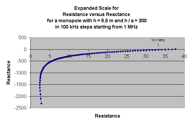
I have calculated and graphed several results to illustrate the effect of widening a structure’s feedpoint impedance. These results are plotted below. The following figure employs an expanded scale to show how the reactance starts off negative, or as capacitance. Notice how the first resonance appears near the low resistance value of 32 ohms – this is probably a little high and would be caused by the Rr term.


This figure shows plots for various h / a ratios, notice that the lower h / a ratios result in plots with less impedance excursions; i.e. a wider structure is easier to feed.
Sadly the links to the Software and the Spreadsheet are not available anymore. – MD0MDI
The wide.cpp program used a Q of 1000 to calculate the parallel conductance G, I could have set this to 0 as it leads to the observable loss at the low frequency end of the plot. With a Q of 50 the loss resistance approaches 20 ohms at the low frequencies, compare this with a dipole in close proximity with the ground.
The series loss resistance R, was assumed to be due to the radiation resistance and the series RF loss resistance due to the skin effect. The RF loss resistance will be much smaller than the RF for the wide structures and could have been neglected.
The analysis of wide radiators is difficult and the use of the transmission-line analogy yields a zero order solution to the problem for the first resonance. Subsequent resonance points will show an impedance which is too large so you should not rely on the accuracy of the plot beyond the quarter-wave resonance, however the plots yield results which are of the right order, even up to the half-wave resonance. (The 3/4 wave resonance shows a resistance term which is far to high.)
It is interesting to note that the evaluation of G is based on the assumption that the radiator has a particular Q. It was found that the G term raises the input resistance at low frequencies, while the R term sets the first and second resonance resistance values.
Originally posted on the AntennaX Online Magazine by Ralph Holland, VK1BRH
Last Updated : 13th May 2024
