Mobile Kilowatt Mast
This is a follow up to the original article on how to make a kW mobile mast, only this time the photos are included to show the finished mast and results after installation. The mast here was used on one of my cars until the engine broke and was too expensive to fix. There are no metric sizes given for some of the pipe sizes as I do not know what is available elsewhere in the world. Just use what you can find that works.
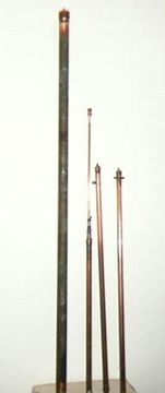
In the photo on the left (Figure 1), the main elements of the antenna are seen. The three small elements were used in the original installation. Also visible is the telescoping top section that went into the top of the coil and is about 4 ft. long (1.3m.) collapsed.
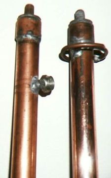
In this photo on the Left (Figure 2), the top and bottom of the mast can be seen. The bottom of the mast can be seen on the left. The large banana plug is where the matching coil plugs directly into the mast. The top section is to the right. The ring that is visible can be used for a guy wire or a capacity hat in another application. The end caps are fabricated by drilling a copper cap out to match the 3/8-24 thread bolt used to fasten the mast to the ball mount and also to fit the particular coil set of mine.

The fully extended section can be seen in here and consists of 4 sections almost 8 ft long (2.4m.). This section was intended to be longer than a normal top section, as this system was also designed to serve as an emergency antenna.
The large diameter, long section of pipe visible to the left, is the bottom of the emergency antenna setup designed to be used from a fixed location. It consists of a length of 2 inch (5.08cm) copper pipe 5 feet (1.54m) long. It was not intended to be used while driving the car. It is meant to be a portable station and used in conjunction with the other sections with antenna tuner. To construct this antenna, some basic torch soldering skills are needed. You must be able to handle a torch and solder well enough to make all of these connections. If you need to, practice on some spare pipes.
To continue, in Figure 6, the basic construction of the end caps is shown. This is the way all of the caps are constructed, regardless of pipe size. First, you must drill a 3/8 inch hole in the center of the pipe cap. After that is done, a copper washer is put into the cap and the bolt inserted through the hole. Next another washer is placed on the outside of the cap. A nut is placed on the bolt and tightened down to hold the whole assembly together while everything is soldered together. I filled the inside of the cap to the top of the bolt with solder, which will keep everything mounted solidly. Depending on what type of bolt you use, the solder may not stick. Stainless steel can’t be soldered so use brass or bronze. Brass also breaks easier but, if you cover the bolt completely with hot solder, it won’t go anywhere. The outside washer should also be soldered in place and the two washers will reinforce the solder cap to help keep the cap from bending under stress. After you finish the soldering and everything is cooled down, then remove the nut used to hold things in place, if desired.
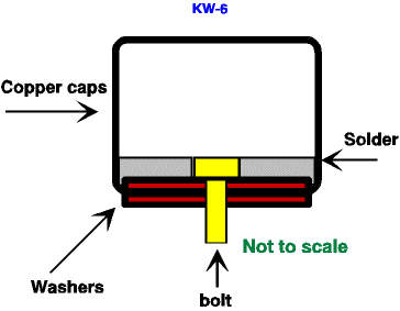
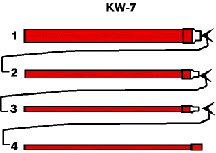
Figure 7 shows how the telescoping mast was assembled. The pipe sections ranged from 1.25 in. (3.17cm) to .25in. (.63cm). The reducers may have to have a shoulder removed from the inside of the small end to allow the smaller pipe to slide inside the larger tubing easily. A rat tail file can do this as will a handheld drill fitted with a rotary rasp.
Next, I put a cap on one end of the smaller pipe, inserted it through the larger pipe and out the reducer. Each reducer has slits cut in them to allow hose clamps to squeeze down on the smaller pipes. The caps on the smaller tubing sections will keep them from being pulled out accidentally. They are not shown in the drawing. Also, the top section was fitted with a anti-corona ball made of two end caps and a small section of tubing.
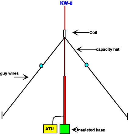
In Figure 8, the entire emergency portable antenna is shown. The large bottom section was fitted to the mobile mast section by using a mobile spring as an adapter. A section of wire should be fitted with terminals that are to be placed across the coil for a better connection than possible through a spring. The coil in this case is part of a set of old Master Mobile coils. I have the entire set of these coils and they cover 160 to 10 meters, with the exception of the new WARC bands. Later a large coil will be constructed for all bands using #6 wire and taps for the different bands.
If you decide to make up all sections for use as a mobile antenna and also for use as a portable antenna, be sure to use the largest pipe size for the bottom sections. By keeping the sections down to lengths that can be placed in a car trunk, you could build up a mast 30 feet (9.1m) or more long (9.1m). Just be sure to use adequate guy ropes to stay the mast. The antenna tuner must be located at the base of the antenna for maximum efficiency. Although not required, it’s a good idea to polish all of the elements and then paint all sections, except for the telescoping section. This would keep the corrosion down and help reduce losses in the surface skin corrosion.
I know that there may be questions why I used copper instead of aluminum. Copper can be soldered and is easier to work with throughout the project. It is also cheaper in many places than aluminum
Originally posted on the AntennaX Online Magazine by Richard Morrow, K5CNF
Last Updated : 24th April 2024
