
The Loadall Antenna Coupler
I had traded for a CU/991 and a Master Chief at N.A.S. Corpus Christi, who had access to the tech manual library, found the diagram and made several copies of the schematics, block diagrams, etc, and gave them to me. Later on when I had some problems with the thing, he gave me a complete training manual on it, possibly because I kept getting tears all over his paper work.
I built a power supply that put out all proper voltages, and got the coupler working. That’s when I found out there is a Santa Claus. That thing would load up all the antennas that I hooked it to and on any frequency fed to it. That is why I called it the Loadall. KB5MO has a later version of the CU/991 called the 490-T, and it would load up a 2 ft. piece of solder on 160 meters, until the heat of the corona would started to melt the solder and as the solder dripped off, load up what was left until it arced again and kept up the process until there was no more solder to melt. Now that is impressive.
Later on, KB5MO and KC5UN hung a 300+ ft. sloping long wire from the biggest bridge in town and operated in one of the 160 meter contests using a Ten-Tec rig and the 490 loaded up that wire just as well. They had a 40+ signal everywhere. Just the thing that most hams with a long or short wire antenna need, an efficient coupler that will load up anything.
Now comes the Sticker. It takes a minimum of 50 watts carrier to drive either the 991 or the 490-T. Unfortunately, most solid state rigs shut down when the SWR gets too high, and the SWR as seen by the transmitter changes as both of these couplers go through the tune-up cycle. Now what?? Simple, you build a manually tuned version.
Figure 1 is the basic RF diagram of the coupler, and as you see, it is not like any coupler, at least for ham use. L1 is an auto transformer, which allows the coupler to match impedance above and below 50 ohms fairly easily.
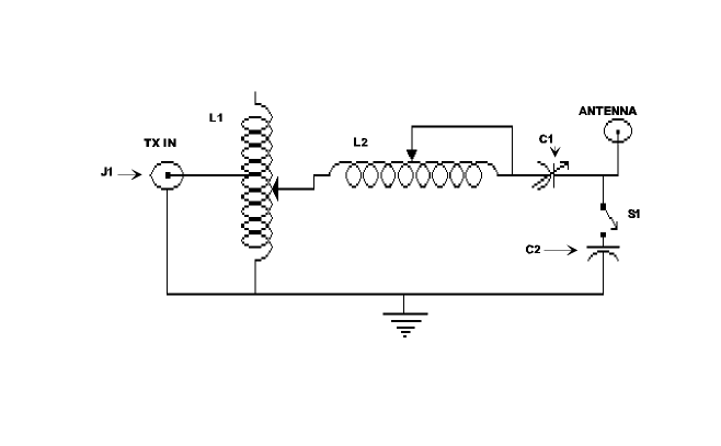
In the case of the CU/991, I believe that the range of antenna impedance that could be matched is in the range from 5 ohms or less to several hundred ohms, which is what the military wanted it to do. And, it is what most hams would like to do. There is no balun since the antennas used by the military were either whips or long wires or any combination of the above. So, no balun. Also there are no parts values listed either. But I found out what they were from a Fair Radio catalog and the parts list will give you an idea what you will need to scrounge up. Fair Radio also sells the CU/351/180L coupler, which is the same thing as the 991 except the 991 has no provisions for a separate receiver. They also sell the parts from the coupler as individual modules.
If you want to wind your own coils, L1 consists of 28 turns of what looks like #19 wire on a 1/2″ (4 cm.), form tapped at 15 turns. L2 is approximately 25 turns of 1/8 silver plated ribbon on a 2 1/2-3″(6.5-7.7 cm), form, but you could possibly use #19, on the same size form.
L1 as you can see, is center-tapped, and making a center-tapped roller inductor can cause a mental hernia, but it can be done. However, most people would rather use switches to vary the inductance. Remember L1 is an auto transformer that will allow a high impedance antenna to be matched and loaded up fairly easily, so unless you will never use a high impedance antenna, use an auto transformer. L1 also resembles a variac, doesn’t it? (for those of you who use short low Z antennas, I will get to you later.) You should use large conductor diameters in the coils to lower losses, as large diameter conductors have much lower RF losses because there is more surface area for current to flow on. Skin effect, you know. End of theory lesson.
L2 is a real humdinger. In the 991 it is a pair of coil forms; one ceramic, the other a silver plated drum upon which a silver plated strap about 1/8″ wide is wound. As more inductance is needed, the strap was wound on the ceramic form, and back on the metal drum when less inductance was needed. Very expensive, and effective, but the military deserves the best, as there is no second place in a war. Again, keep in mind what your power levels will be and construct accordingly.
This coil could be wound on a piece of PVC pipe with both ends capped, and an insulating rod running through the center of the caps, allowing a roller inductor to be easily made. Spacing of the turns should be equal to the diameter of whatever you use for a conductor. Just remember the more turns that you use the greater the loading capacity you will have, to a point. Two hundred turns of #10 might be a little to try to use to load up a 3-ft. hunk of barbed wire. It would also be expensive to buy that much wire. If you stick fairly closely to the values given, you can’t get too far off base and it will work ok.
In the military boxes, C1 is a motor driven vacuum variable, expensive but effective. most of us will have to be content with a wide spaced 3 gang 365 pf. per section broadcast variable, which will work fine. Again, this will depend on how much power you run. For the 100-150 watt rigs, this should work fine.
I will not guarantee that C1 will not ever arc, but then all that you have to do is to cut back on the power of change the antenna length one way or another. As for C2 it is used under conditions when proper loading cannot be obtained no matter what settings are used.
Figure 2 is a low impedance version of this coupler that is primarily for low impedance antennas that are shorter than 1/2 wavelength at the highest operating frequency that you operate, such as a 23 ft. wire on 80/40/20.
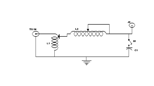
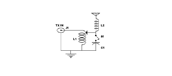
Figure 3 is for mobile antennas with body mounted ball mounts, not bumper mounts. In Figure A-3, L1 becomes an impedance transformer to match the coax and transmitter impedance as most mobile and other types of shortened antennas are usually lower than 50 ohms. For an example, a 1/4 wave vertical with a good ground has about 36 ohms impedance at the feed point, so you need some way to match the 50 ohm feedline and 50 ohm output of your rig to the feed point impedance. A mobile on 160 or 75 meters is even worse, around 25 ohms or less on 75, and I measured the base impedance of my 160 meter mobile antenna at 13 ohms on my Corvair van. So as you can see, to increase antenna efficiency, a good match is really important.
I might add that this type of coupler is very common on marine ssb rigs in the 2/4/6/8 MHz range, as most of the time, the only antenna on board is a 23 or 36 ft. fiberglass whip, a backstay antenna on a sailboat, or a long wire running from the bow to the stern of the ship. As you can imagine, none of these antennas are very good antennas on 2 or 4 MHz, even with a center loading antenna, so to increase the radiation efficiency, a coupler of this type is used. It is either built right into the rig or is a remote tuned box that is mounted at the base of the antenna. If installed and tuned up properly this coupler works very well. If you operate only on the lower bands this might be all that you need.
Keep in mind when you build this coupler, you need to keep the two coils at right angles to each other or end to end so as to keep coupling between them to a minimum. If you don’t, it will cause some very goofy tuning to occur and you can count on lots of TVI. Not to mention stray RF floating around.
Putting a partition between the coils is fine, but you must try to keep the coils as far as possible from the chassis and sides in order to keep the total circuit Q as high as possible. You must also have an insulated coupling between the shaft of C1 and the knob that your little pinkies will be twisting or else you will feel great pain as the output of your rig barbecues your fingers. I am speaking from experience, as I have had my fingers burned when RF arced from the set screw in the knob on a capacitor to my fingers, sometimes jumping as much as 1/4 inch to get to my hide. So don’t say that you weren’t warned.
A few more construction hints are in order. Use toothed washers under every ground connection to cut though the ever-present aluminum oxide found on every aluminum chassis. By using this type of washer skin resistance is lowered and losses are also lowered. Keep leads short and use as large a conductor as you can to keep the losses down. Coils in an antenna coupler can carry very large currents, and because of this, heat will be generated, sometimes melting the coil form and ruining your day. Besides, every little bit of RF wasted as heat in your coupler is that much less RF that can be heard where you want it to be heard. You might want to solder all chassis grounds together with large diameter copper wire, just to cut losses some more.
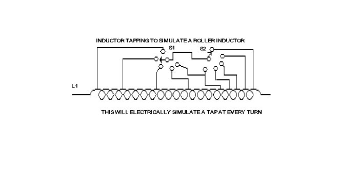
S1 can be any type that can carry a goodly amount of current and not get hot. A banana plug will do for most cases just as long as you do not unplug or plug it in with the rig keyed up, arcs and sparks, you know. Just be sure that you get something that does not leak at the higher frequencies. Figure 4 will show you how you can come up with a fake roller inductor. All that is needed is two identical rotary switches, and to wire them up as shown. This will give you a coil with a tap at every turn. If you have two five position switches tap the coil at every five turns and connect to S2 and S2 to S3 as shown, with S2 wiper wired to S3 wiper and wire S3 up s shown with a tap at every turn. Switching S2 gives a coarse adjustment with S2 giving five turn jumps of inductance, and S3 giving one turn increments of inductance. Sneaky isn’t it? Just remember that the two switches must have the same power handling capabilities as well as the same number of switch positions. Needless to say, L2a and L2b also must be identical. You can also use this switch setup on L1.
Now that you have gotten the Loadall built, the next thing to do is to hook it up and load up whatever you have for an antenna. Remember, this coupler was designed to load up a single wire or whip, not coax fed dipoles unless you short the braid to the center conductor and use it as a “T” antenna. Long wires, whips, barbed wire fences or your car can be loaded up. Big cars load up easier on 75 and 40, I might add. First thing that you will need is an SWR bridge, or watt meter. Hook it up and set it for forward power, max sensitivity. Set L1 to the center tap, or top of the coil, if you just built the low Z version. L2 goes to the middle of its range, C1 to max capacity, C2 out of the circuit. Next key up the rig on cw and bring up the carrier level until you start to get a reading. Raise the carrier level until you get about 1/2 scale on the SWR meter. Then adjust L1 one way or another until the power starts to increase. Adjust L1 for max forward power and calibrate the SWR bridge. Then adjust L1 for minimum SWR. Next tune L2 for max forward power.
If you go from max L to min L and don’t get much power out, Then set L2 so that there are about 6 or 7 turns in the circuit, and tune C1. If the power goes up then tune L2 some more to see if that helps. Alternate between L2 and C1 until you get max power out, then adjust L1 for minimum SWR. If you don’t get max power out, then switch in C2 and start with L2 after setting C1 at max. Remember there must be some of L2 in the circuit at all times, as it forms a series tuned circuit with C1, and in order to tune your antenna there must be some inductance for C1 to work with, not just antenna inductance. This is a basic tuning procedure and you can modify it to fit your antennas tuning.
A field strength meter will help you confirm your loading as will an RF ammeter. particularly on the lower bands and will keep you from loading up the coupler and having RF all over everything. The military boxes didn’t do this as they had all kinds of loading and phasing sensors to keep this from happening, but we don’t, so it can happen. The tuning up of the low impedance coupler is basically the same except that you start at the top of L1 and go towards ground. Now for you chaps that just need the low Z mobile matcher for the car here is what you do.
First, park in the clear, with no metallic objects around that might cause tuning errors due to coupling to the antenna. Beware of power poles as they all have a ground wire that runs from to bottom and can really throw everything off. I am speaking from experience again. Once you are in the clear, start with the lowest band that you are on, and connect your antenna lead to the top of the coil where the coax is connected, and tune the antenna loading coil (which has become L2 in the diagram,) or minimum SWR. When you get minimum SWR, then start tapping down on L1 for minimum SWR.
This will change the resonant frequency of the antenna, usually shifting it down, so find the resonant frequency again and set L1 for minimum SWR. When L1 is set, then tune your antenna loading coil for resonance at your operating frequency. By using a rotary switch that can stand the power, a multiple band matching system can be set up. Solder your final connections to the matching coil. C2 is an option that might be needed on the lower frequency bands, if you have a problem tuning up. Just alligator clip a 100 pf. from the antenna connection to ground and see if that helps. If not there is something wrong somewhere else. If the addition of C2 from the antenna to ground fixes the problem, add a capacitor that will handle the rigs power without heating up. If you operate multiband, be sure that the capacitor can be disconnected when it is not needed.
If you operate on ten meters you will find out that even on ten meters, a matching network will help as the base impedance of a ten meter loaded antenna is not 50 ohms, nor is that of a 1/4 wave (8 ft. whip). The base impedance of a quarter wave antenna on any frequency is between 25-36 ohms. The impedance of a 1/4 wave mobile antenna could be less. This does apply to a magnet mount base loaded antenna, as the required matching is done in the base.
For L1, I used a length of B&W coil stock when I made up this matching system for my mobile, and it has about 12 tpi (12 turns per cm), and is about 2.5 or 3 in. in diameter (7-7.6 cm.). It is easier to use air-wound coils than a toroid, because of the need to tap the coil, as you can make your connections easier than on a toroid. A toroid will work, and if you want to use one, you are on your own.
Just keep the coil as far away from the car body as possible, and can still keep your leads short. I grounded my coil and the coax to the same place, and used star washers to cut through the rustproof coating present on the inside of the body. By doing this, you help to insure a good ground connection to the body of the vehicle. Putting the star washers between the ball mount backing plate and the body of the vehicle, will insure a corrosion proof ground connection between the mount and the vehicle. Corrosion can’t get to the metal where the star washers cut into the body of the car and the backing plate, as this is a pressure point. You should spray Rustoleum on the backing plates and nuts, just to be safe if you live in a salt water or other type of corrosive atmosphere.
You need to keep in mind that your car or truck is the other half of your mobile antenna system, and good connections to it are very important to lower losses, particularly on 160, 75, and 40 meters. Good low loss connections are very important to a mobile installation, as we are forced to use a very inefficient antenna on these frequencies.
Remember that this matching system was not intended to be used with a bumper mount. Trying to match up an antenna as well as a length of coax might be difficult on some bands, and may not work at all on others. So remember, you have been warned.
Now to review what has been discussed so as to give you a clear picture of what this coupler is capable of doing for you, if you do your part and use a good ground, etc.
1. Match antenna impedance from lower than 5 ohms to several hundred ohms.
2. Allow you to load up the antenna after it is matched to your rig.
3. Tuning range from below 1.8 MHz to 30 MHz depending on parts values used.
No. 2 needs some explanation, as it sounds confusing. There are some couplers on the market that can match your rig to an antenna and allow you to radiate a signal, but not nearly as efficiently as resonating it, if it is a non-resonant long wire. Marconi said if an antenna was too short, make it electrically longer with a coil, if it is too long shorten it with a capacitor. That is what L2 and C1 do respectively.
There are some additional comments that I will pass along. First, if you use the dual switch method of tapping L2, set C1 almost but not quite to full mesh. This will allow you to have a vernier tuning that you would normally have with a roller inductor, only in this case C1 provides the fine adjustment, if the best loading point seems to fall between switch position of S3.
Second, if you have a very long run of wire inside your abode to your antenna, keep it away from anything metallic, and keep it insulated. DO NOT USE COAX FOR THIS JOB. The coupler won’t like it and neither will you as you can load up the coax and not the antenna and RF will be everywhere. The Loadall will (through inductive and capacitive coupling), load up any metal object that is close to your feedline; lamp cords, electric blankets, pipes in the wall, the house wiring, bathtub etc. This can cause TVI and any other kind of I possible and loss of signal to the antenna.
Using good high quality insulation is very important, because even at the 100-150 watt level a lot of voltage can occur at high impedance points on the antenna or feedline. It is possible for these points to occur inside the house at some frequencies, and the resulting arc might set fire to your DX cards, the couch, the walls, or the cat. There is also the possibility of someone getting an RF burn, setting legal fires that can incinerate your money for a long, long time. Consider the placing of a long feedline inside of small PVC pipe. ‘Tis better to be safe than homeless.
The third comment that I will make and stress is the importance of making good ground connections and antenna connections. DO NOT rely on your coax to supply the ground connection to the Loadall, run a separate wire to it and ground both the rig and the coupler to a good ground. If you don’t you can be assured that sooner or later you will get a kiss of fire from your microphone. An arc to your fillings will really light up your life.
Remember, this coupler was made to load up a single conductor antenna, not a dipole! So keep this in mind. It was made to be used at a remote point to load up an antenna or a whip allowing antenna matching and tuning of the antenna where it will do the most good… at the antenna.
I hope that one of the two couplers will be what you need and that the matching network for mobile use will help the old mobile signal. This coupler is excellent for Field Day or portable and emergency use. “So don’t leave home without it!” It is interesting to note that the military is still using the CU/991 and its kin. I saw a 180L in a C130 that the Marines had on display at an airshow here last year. A good design is hard to beat, or even match.
The last and most important comment that I will make is that this is a Collins Radio design and as such is covered by about two or three thousand patents. So if you are contemplating manufacturing this coupler for sale commercially, DON’T!! You run the very high risk of being sued until the sun goes out
So good luck with your construction project, scrounge what you can, build what you can and buy what you must, but build a Loadall. It will make your single wire antenna radiate better and that is what counts. May Your Force Be Radiated
Parts List
1. L1 = APPROX. 14 MICROHENRY, CENTER TAPPED
2. L2 = APPROX. 28 MICROHENRY.
3. C1 = 7 TO 970 pf, 3 KV VACUUM VARIABLE
4. C2 = 100 pf. ?KV, 10 or 15 KV ok
Figure 3
L1 =8 TPI, No.12, 3″ diameter, spaced the thickness of a dime.
L2 = Mobile antenna loading coil for the band in use.
Originally posted on the AntennaX Online Magazine by Richard Morrow, K5CNF
Last Updated : 15th March 2024