LAB NOTES: These Capacitor Antennas
Over the past year, I have investigated many aspects of the CFA antenna, learning many things along the way. Things such as: “matching is not radiation” and “superposition reigns supreme”. I found that the CFA is but one of many systems of small E field and H field sources that can be tried. Representative E field sources include: the E plate of a CFA; the Isotron antenna and related antennas like Old George’s (George Sharp, KC5MU) “pizza pan antenna” (see this month’s Ham WorkShop). Representative H field sources include the old-fashioned small loop antenna; the DLA (double loop antenna) and a properly configured capacitor such as the CFA D plate.
Capacitor Antennas
The Isotron, the pizza pan antenna, and perhaps a loop that resonates with very little capacitance across the open gap all seem to be versions of the same thing – a large volume, small value capacitor parallel resonated with a large value of inductance. The high L/C ratio means that the capacitor has to have extra high voltage across it in order to store the large amount of cycling energy stored at other times as magnetic energy in the inductance. This energy cycles back and forth between the two components during the RF cycle, and since the E field energy storage is out in the space between the plates, some is lost in radiation. In one quick test, I found that the CFA E plate alone driven by the minimum lead length tuning configuration, described in my June 2000 article, radiated about the same as a capacitor made out of two screen bowls used to cover food dishes against flies. The capacitor was fed at the closest point of the bowls, like this: )^( where ^ is the end of a coaxial cable. The many configurations in the Isotron catalog suggests shape is not too important for E field radiators.
The JEF Drive

This month, inspired by Jef’s interesting method of feeding a loop, I decided to see if it can usefully be combined with an E field source. I have a hexagonal loop made of 1-inch (2.54 cm) copper water pipe with a diameter of 29.75 inches (75.5 cm). It tunes down to 7.1 MHz with a huge 800 pF double stator transmitting capacitor. With minimum capacitance it is resonant at about 24 MHz.
The experiment consisted of coupling the signal generator to the loop and measuring the RF signal level at the outdoor sense antenna 55 feet (17 m) away, then adding a radiating capacitor to the ends of the loop and observing the signal changes.
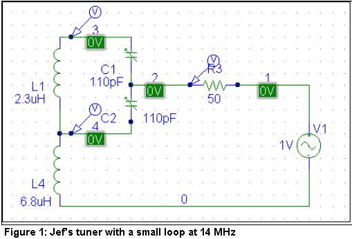
Table 1 gives the component values associated with the tuner shown schematically in Figure 1.

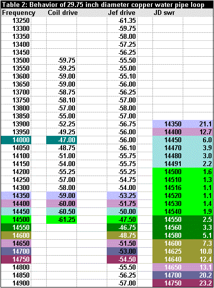
The first test was to set the resonant frequency of the loop and tuning capacitor to 14 MHz when it was loosely coupled to a small coil. About a foot of #14 insulated house wire was wound around the pipe, and the turns were spread apart so that the coil extended along the pipe about 4 inches (1.6 cm). The drive cable had short clip leads that connected to the ends of the coil. This gave a connection to the loop with an SWR of about 2.8:1 with minimal distortion of the tuning curve. The first column of data in Table 2 shows the tuning curve of the loop alone.
The tuner of Figure 1 was then connected. The first thing I noticed was that the loop was “hot” on only one side! Touching one side caused big changes in the signal strength, while touching the other side caused no changes. The radiated signal had a notch or dip in its strength at the frequency where the peak had existed in the loop alone! The second column in Table 2 shows the frequency response with the new tuner, with the setting of the tuning capacitor unchanged from its “loop alone” position. At first, I had thought that the peak at 14.500 MHz was weaker than the bare loop’s peak at 14.000 MHz, but the data shows they are about the same amplitude, -47 dBm.

The signal generator was then disconnected and the MFJ-249 SWR analyzer attached to the loop. The low SWR values coincided with the radiation peak frequencies, but the bandwidth of the good match is very narrow-about 80 kHz between the 3:1 frequencies. The colors in Table 2 show which data in the SWR column relates to various frequencies in the tuning curves. The SWR data covers a much smaller frequency range than the other 2 columns.
Having determined that the loop was working correctly, I added a radiating capacitor consisting of two 6-inch (15 cm) long cylinders about 5 inches (13 cm) in diameter and about 0.25 inches (6.35mm) apart, end to end-like a short, fat dipole. This capacitor was positioned along each of the possible axes centered in the plane of the loop. Each direction-an x, y, or z axis (x and y in the plane of the loop)-required retuning the big capacitor to move back to the desired frequency, but the maximum signal was always exactly the same level.
I must conclude that there is no augmentation of the radiating ability of the loop by any kind of “capacitive hat” connected to the loop ends.
When I tested the circuit in the spice program (PSpice), it showed that with the values measured, it should tune to near 7 MHz, not 14 MHz!! I went back and re-measured everything and found variations in the shape of the curves, but no change in the frequency. I computed the expected inductance (L4 in Figure 1) and got 6 uH, near the 6.8 measured at a low frequency. The coil appears to have enough distributed capacitance to be self resonant at about 25 MHz. Spice shows behavior similar to the measured curve when the inductance is under 1 uH and I think the distributed capacitive reactance is reducing the effective L at 14 MHz to under 1 uH. Shortening the drive cables to only 5 or 6 feet (1.3 – 1.8 m) long and inserting stick attenuators calmed down the variations in apparent radiation at frequencies far from the loop resonant frequency. Evidently the combination of long cables and the high “off frequency” SWR made the cables radiate.
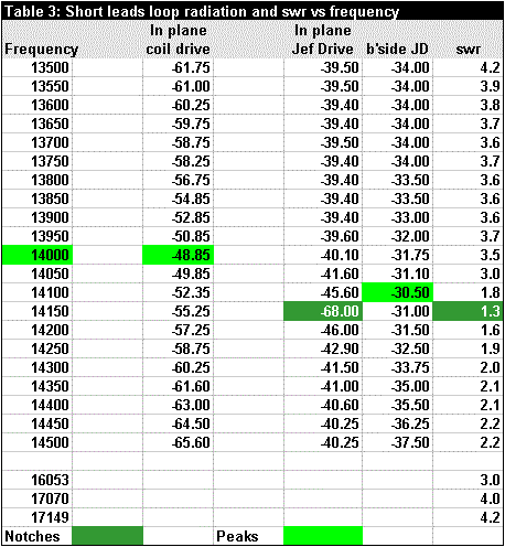
Table 3 shows the same tests as Table 2, but with short leads and attenuators in the lines to prevent radiation. The first column shows the resonance of the loop alone excited by the coil of wire around the pipe. The second column shows the result scanning frequency and driving the loop with Jef’s tuner. The notch at resonance is tunable from 7 to above 18 MHz.

In all the tests except the third column of data, the loop was oriented so that the test antenna 55 feet away was in the plane of the loop. For the third column of Table 3, the loop was rotated so that the test antenna was on a line normal to the plane of the loop. It clearly shows that the “notch” in the second column data becomes the “peak” in the third column! The peak is small because this is a low-gain antenna. The notch is deep because it shows the energy left after the radiation shifted at resonance to the proper “loop” pattern in space! Thus, the notch is just a radiation pattern change! I guess I have to modify the mantra “matching is not radiation” to add “at least, in the direction you are looking!” if the antenna is directive!
The next experiments will be the comparison of several E field radiator configurations and the loop antenna at 14 MHz. This will require a roller inductor to be mounted between the two plates of the antenna “capacitor”. The inductor available needs more cleaning in order to be adjusted with RF “on” without making a lot of “noise” in the radiated signal due to the dirty roller connection.
This month I also put up an ordinary 20-meter wire dipole. Unlike my small antenna efforts, it appears to radiate. I had QSOs with the first two stations I called. They were located in Oklahoma and Texas-a good distance away from Oregon! Meanwhile, back to the drawing board!
Originally posted on the AntennaX Online Magazine by Joel C. Hungerford, KB1EGI
Last Updated : 31st May 2024

