The Carolina Windom Antenna
Background Information
Loren Windom began with the basic concept but soon made changes. He reasoned that a basic half-wave dipole exhibits an impedance of approximately 72 ohms at its center, rising to several thousand ohms at each end, and consequently there must be points outward from the center that should exhibit 300 ohms, 450 ohms and 600 ohms. Measurements showed this was in fact the case. He then sketched an 80-meter half wave antenna to scale, and superimposed half-wave antenna voltage and current distributions for other, harmonically-related bands on to the basic antenna. It became immediately apparent there was a point on each side of center where virtually all even-harmonic bands showed a cross-over at approximately 300 ohms. This turned out to be the case in practice, as on 80, 40, 20 and 10-meter bands, the standing-wave ratio was reasonable with not too much reactance. The 300-ohm location was suited almost ideally for 300-ohm balanced feedline, so in later years the single-wire feeder at 600 ohms became the “twinlead” feeder at 300 ohms. This, in fact, necessitated a change from a feedpoint approximately 16% off center to one only 14% off center, where the “natural” 300-ohm impedance occurred.
When the fifteen-meter band opened up in the early 50’s many hams tried to use their Windom antennas on that band, too, but it wasn’t the huge success that they had hoped. Fifteen is an ODD harmonic rather than an even one, and the feedpoint impedance was not 300 ohms resistive; it was something different, and reactive as well. Thus, the antenna tuner became a necessity to operate the Windom on fifteen meters. At this point it might be worthwhile to talk briefly about transmitters and tuners, and how they evolved.
Tube vs. Solid-State Final Amplifiers
In the forties and fifties, and of course before WWII, the majority of transmitters (transceivers weren’t generally available in those days) had two basic types of output coupling in their final tank circuits; a wide-range Pi network capable of feeding a single wire, or a balanced link output capable of feeding balanced twin feeders of 300, 450, or 600 ohm impedance. In general, tubes were far less sensitive to various output impedance than the solid-state amplifiers in today’s radios. Antenna tuners were not common, or even readily available unless you built one for a special application or used a surplus military one. The built-in variable capacitors and inductors used in the tube “finals” were sufficient to load almost any antenna you had. Sometimes an “L” network was constructed to allow use of an end-fed long wire.
Then, solid-state finals and transceivers came on the scene. The transistor finals were finicky and hard to please. Engineers decided that since coax was the most frequently used feedline, they would design their final amplifier circuits to accept a fixed 50-ohm resistive, non-reactive load…where the “load” was the feedline impedance AND the antenna feedpoint impedance. Lacking the ability to handle reactive loads, many transistors bit the dust…unable to handle the mismatch between nominal 50-ohm output and some other reactive value of load impedance. Rather than make final amplifier tank circuits that could be tuned to resonance and couple to these loads, they decided to build “shut-down” circuits into the transmitters and transceivers that would reduce power whenever a reactive load was sensed. Now, it became impossible to use some antennas with a solid-state rig unless you had antenna tuners OR a matched antenna with a non-resonant feedline.
One answer to the multi-band antenna problem was development of “trapped” antennas which would, hopefully, present an essentially 50-ohm non-reactive load to the feedline and to the transmitter. “Traps” were inserted along a half-wave length of wire on 80 meters to isolate various portions of the antenna from each other. These so-called “multi-band” antennas now were usable by most transmitters of the solid-state variety without antenna tuners, but they had one possible disadvantage; they used only a part of the entire antenna on every band except the lowest frequency band, effectively trapping out other portions. Quarter-wave vertical antennas used the same principle; and overseas, foreign hams began calling these multiband trapped antennas W3DZZ antennas, named after the ham who wrote an article in QST about how to build and use the traps.
Windom antennas gradually disappeared from the scene and were seldom used, or even heard of, by the newer generation of radio amateurs.
The Carolina Windom – An Old Friend Revitalized
A trio of enterprising and imaginative Windom enthusiasts resurrected the basic Windom design and made some interesting changes as a result of their experiments. Jim Wilkie, WY4R; Edgar Lamber, WA4LVB; and Joe Wright, W4UEB did the work; and, in Jim Wilkie’s words, here’s what happened.
“I had just gotten my IC-751A and TS-440S, but the only antenna up was a moth-eaten old sloper. To add to the problem, I had very little room in which to put up a really good antenna…so the only thing we could do was to build one.”
“I had been talking with Edgar Lambert, WA4VLB, down in North Carolina for some time about putting up something new. Edgar spent many hours in discussion with me about the possibilities of either a 3/8-5/8 wavelength antenna, or a 1/4-3/4 type, both of which we were anxious to try…but in the event, we put up neither one. Instead, we decided to try a different approach; first we liked the idea of off-center feed, and the Windom filled the bill. However, we liked the idea of using coax and concluded that by sliding the feed point back and forth, we could match 50-ohm coax line to the flat top — and, if one had a good tuner, it should work. Edgar did all the climbing, and Joe gave us his input on 2 meters. How well the result worked was a surprise to everyone!”
“We knew the theory was all wrong from the beginning; a Windom feedpoint should be 300 ohms, and using a 4:1 balun wasn’t right, but we wondered if the balun might be used as sort of a loose transformer instead of performing the normal balun function. The initial tests provided great reports from all over the United States, and I used the antenna for some months before deciding to turn it over to Jim Thompson, W4THU and his Radio Works Company for marketing.”
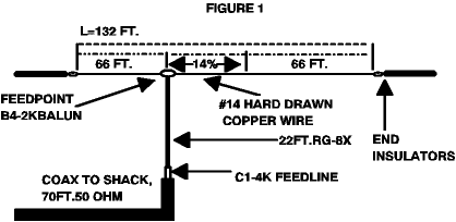
“Jim tried many versions of the antenna and found that a 22-foot length of coax from the feedpoint at the flat top down to another balun (a 1:1 in line toroid type) made coverage of the upper bands easier. Personally, I don’t use the second balun (feedline isolator) but use 44 feet of coax directly to the antenna tuner. It works just fine, and W1XU can attest to the signal strength at his location.”
The Carolina Windom appears to have some gain on the bands above 40 meters. On-the-air tests by over 100 hams to date have shown that the CW is an effective “DX” antenna (perhaps by virtue of its vertical 22-foot radiating section of coax) and has outstanding anti-fade properties. since its introduction, the CW has been a winner for radio amateurs who have need of a simple multiband antenna. Impervious to weather, it laughs at rain and snow, and it really “gets out.” Many of the older tube-type radios may be able to use the Carolina Windom without an external antenna tuner — a big plus for simplicity — but for those who use solid-state rigs, almost every hamshack boasts an external antenna tuner…and nowadays many of the newer rigs have built in tuners.
Our Tests of The Carolina Windom
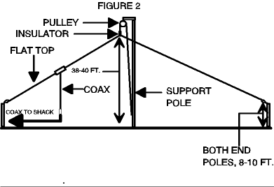
The staff antenna was put up in an inverted vee configuration with the apex at the minimum recommended height: 30 feet. The very complete literature and instructions suggested 40 feet or even 50 feet as being preferable…but we felt that not giving the antenna the best possible environment might prove to be more revealing than placing it in an ideal location. Many tests were conducted on all of the amateur bands between 80 and 10 meters. In the case of our antenna it was found that a tuner was needed — even for 40 and 80 meters…and this was not surprising because of the antenna placement and proximity to ground, trees, a building and other objects. Strangely, moving the feedline close to the support mast, or the recommended fifteen feet away, did not seem to adversely affect the tuning. There was absolutely no problem in achieving a 1:1 VSWR on the input end of the feedline, and the transceiver seemed pleased to see the non-reactive 50-ohm load by putting out its rated power without hesitation on all bands. While on the 80-M fundamental and 40-M harmonic bands the Windom appeared to radiate best broadside to the antenna, it appeared increasingly directional toward the ends of the wire on higher-frequency bands. This was to be expected, and is typical of multi-band antennas where their length is an appreciable part of a wavelength — or even several wavelengths — on the higher bands.
All in all the Carolina Windom proved to be a very satisfying antenna to install and use. Signal reports were very good in most cases, and often better than those from the comparison vertical antenna, particularly on 40 and 80 meters. Those who worked on the antenna and helped install it at the test location remarked about it being an “ideal” antenna for a Field Day exercise. Rugged, quality components were noted throughout and there was never any fear of pulling it taut or tugging the feedline into position. Given a decent support, such as a flagpole or similar structure, you could have your Carolina Windom up in just a few minutes. Tying the ends to convenient supports at a height over 6 feet seemed only reasonable.
There is an axiom about antennas to the effect that a good receiving antenna will also be a good transmitting antenna; and vice versa. So it seemed to turn out in our case. We tried the antenna on most of the popular short-wave bands, with and without an antenna tuner. Signals of very acceptable strengths were easily received in both cases, but when your world band receiver has an “S” meter, you can visually notice an improvement in received signal strength when the antenna is “tuned” by means of a simple antenna tuner. It’s often called “peaking it up” and does make a difference. Generally speaking, the larger an antenna, the better it will receive, due to its increased “aperture”; i.e., the amount of wire intercepting the wave fronts of the oncoming signals.


Configuration Details
In its present configuration, the Carolina Windom consists of a 132-foot length of #14 stranded hard-drawn copper wire and 22 feet of RG8X coaxial cable. The feedline isolator is a Radio Works C1-4K balun, and the matching unit is a Radio Works B$-2K — both provided with the antenna. Yes, they have uhf connectors already attached! Power rating is 1500 watts ssb or cw.
The assembled system (less feedline which the buyer provides) is listed at $75 direct from The Radio Works, or from selected dealers. For more information call or write Jim Thompson, c/o The Radio Works, P.O. Box 6159, Portsmouth, VA 23703.
Lately, Jim has been testing various lengths of coaxial feed line to see if there may be some “magic” length that would allow use of all the bands without a tuner. Although not yet conclusive, a length of 163 feet looks promising. The recommended length is 70 feet.
If you try a Windom, there’s a pretty good chance you’ll really like it. W1XU
Originally posted on the AntennaX Online Magazine by James H. Gray, W1XU
Last Updated : 8th March 2024
