A Visit to the Half-Square Antenna
Experiments provide interesting information.
What really impressed me from the article was that the author, when working into Antarctica “could get a 5/9 report barefoot and break into a pileup any time” when using this antenna. From my limited experience, I considered this to be no mean feat and filed the article for use the moment I had settled down and had invested in the necessary infrastructure to also put up one or more of these antennas. In the meantime, I also collected any other applicable literature.
That day partially arrived during the first quarter of 1997, and it was with great enthusiasm that my first 20-meter effort was put up on two 6-meter masts. I felt that this would reflect the capabilities of the 40-meter version planned for two masts, each 12 meters high, as the “main course” at my QTH.
Basic Half-Square Antenna
The basic form of the antenna is two quarter-wave verticals spaced a half-wavelength apart (Figure 1). They are connected at the top by a single wire. Use can be made of either voltage feed at the base of one of the verticals, or current feed between one of the verticals and the horizontal line.
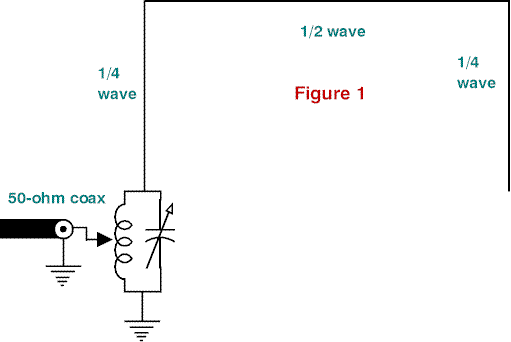
According to previous articles, the half-wavelength spacing between the vertical elements combined with the half-wavelength horizontal line produces a bi-directional, broadsided, vertically polarized radiation pattern. There is supposed to be very little radiation from the horizontal tine.
First Antenna
It was convenient to use a current feed for my first 20-meter version as the shack was on the first floor of the house (Figure 2). The feedline could then run horizontally, at right angles from the antenna to the transmitter. This would guarantee minimal interaction between the feedline and the antenna for the first round of experiments.
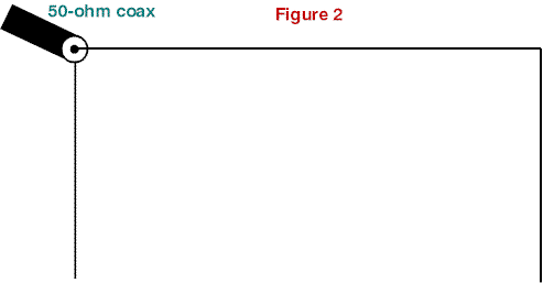
When I was trying to match the antenna cut to the formulas presented by GW2DDX2 the first signs of a snake in the grass became apparent. The antenna did not resonate properly! I trimmed the various dimensions until an acceptable match was found. Somehow this didn’t seem quite right. It became obvious that I would need to put some thought into the physics of the Half-Square antenna rather than blindly follow the advice of others.
According to transmission-line basics, a half wavelength transmission line transfers a load from the one end of the line to the other with only a 180-degree change in phase. In other words, the far end verticals’ impedance is transferred to the feedpoint with only a phase difference. Keeping this in mind, the Half Square antenna can be simplified to a common dipole antenna to aid matching the antenna.
From this, one can deduce that each vertical should be 0.95 of a quarter of a wavelength long, or a fraction shorter to compensate for ground effects. The horizontal line between the two verticals must then be exactly a half wavelength long. I adjusted all the lengths to comply with the above deduction, and it resulted in an antenna with a very acceptable match.
When a voltage feed is used, as is normally the case for the Half-Square antenna, any reactive load presented by the antenna is resonated out by the parallel resonant circuit used for transforming the 50-ohm feedline impedance of the antenna. This enables an antenna with slightly different dimensions to present an acceptable match, although the antenna might not radiate exactly as intended.
Practical Results
As a reference antenna, I put up a version of the G5RV multiband dipole, improved by ZS6BKW (Figure 3)3 at a height of 12 meters This antenna presents an acceptable match to solid-state power amplifiers (SWR < 2:1) without the help of an ATU. It resonates on 3, 6, 7, 14, 18.1, 24.9, 28.5, and, as a bonus, on 51.2 MHz.
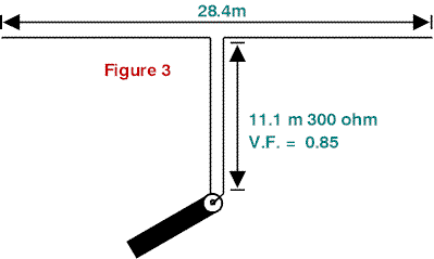
I put up the improved G5RV in a nearly 30 degree south of east direction. As a result, the main lobe on 20 meters was aimed towards Siberia.
When the G5RV consistently outperformed the 20-meter Half-Square antenna by a considerable margin, I was very disappointed. Even lifting the Half-Square to 9 meters did little to improve matters. After many comparative tests, I had to accept defeat. The Half-Square antenna had been thoroughly beaten by a multiband dipole. I had to find the reason why! I decided to call in the help of an antenna simulation program. Danie Brynard, ZS6AWK had a copy of EZNEC2* by W7EL that explained things a bit.
Performance Capabilities
I simulated both antennas over average ground at a height of 12 meters (Figures 4 and 5). The bottom of the verticals of the Half Square antenna were at 7 meters above the ground. I decided that a radiation angle (wave angle) of 11 degrees above the horizon was realistic for my QTH, and calculated the radiation patterns of the antennas for this elevation. The results from the computer simulations were, to say the least, enlightening.
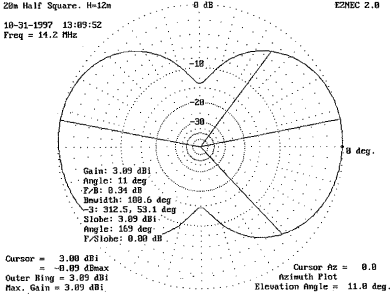
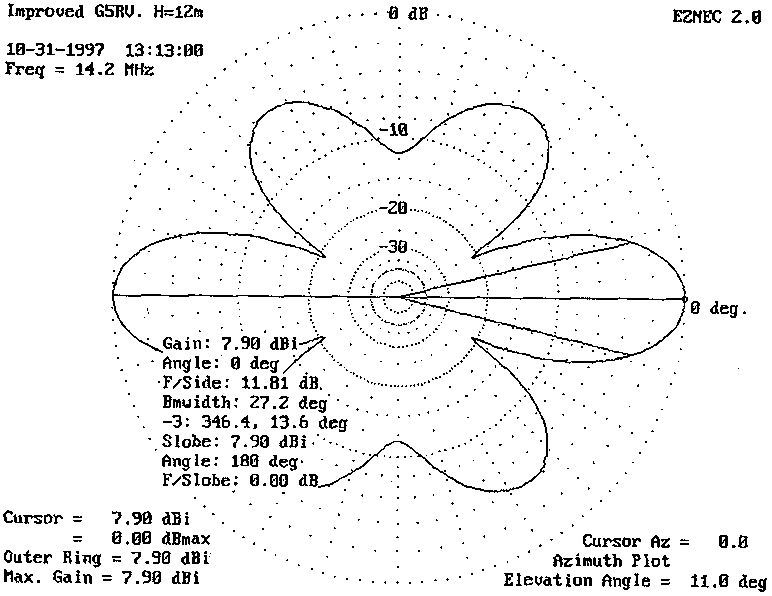
The Half-Square antenna delivers 3 dBi of gain per main lobe. This is fairly realistic for two phased verticals spaced a half wavelength apart. The improved G5RV’s gain came to 7 dBi in the main lobe. That explains the results of the on-the-air tests. The reason for this higher gain can, to an extent, be found in the fact that the legs of the multiband dipole are considerably longer than those of a 14-MHz half-wave dipole. Results on higher frequencies produced even more respectable gains. This antenna is definitely going to spend a lot of time on the higher bands once the sunspots decide to become active again!
Forty-meter Performance
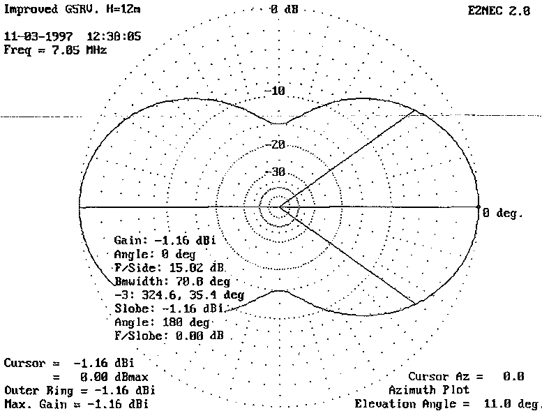
The Half-Square antenna was originally intended for use on 40 meters, but I thought it might be possible to salvage something on the lower frequencies. Once again, the improved G5RV and the Half-Square battled it out on the computer for supremacy at a wave angle of 11 degrees above the horizon (Figures 6 and 7).
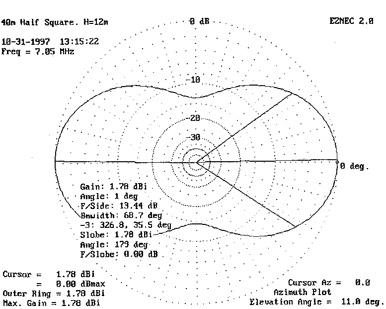
The Half-Square antenna delivers a bi-directional pattern with a simulated gain of 1.78 dBi. The nulls in the direction of the antenna are nearly 13 dB deep. All in all, it delivers very useful performance.
In comparison, the updated G5RV delivers a semi figure 8 pattern with a maximum gain of -1.16 dBi. This is fairly realistic for a dipole at close to a quarter-wave length above ground.
The gain difference between the updated G5RV and the Half-Square antenna is nearly 3 dBs in favor of the Half-Square. With a weak signal, this can make the difference between a station worked or a contact lost. Although not as deep as that of the G5RV, the nulls in the Half-Square’s pattern can help to reduce off-axes QRM and improve the received S/N ratio under certain conditions. For me, the higher gain tilted the scale in the favor of the Half Square antenna.
The next step was to be able to change the radiating direction of the antenna to make optimum use of band openings with the current lull in sunspot activity.
Changing the Direction of Transmission
In W8HXR’s article, it’s claimed that the antenna can be changed from a broadside firing array to an end-fire array with the aid of a quarter-wavelength transmission line. The transmission line is shorted at one end to accomplish an end-fire pattern or left open for the original broadside pattern. The idea is to add an additional 180-degree phase shift between the two verticals that can be switched in or out as needed.
Little red warning lights should start to flash the moment you look at the antenna shown in Figure 8. With the phasing line at a distance of a quarter wavelength between the vertical radiators, and also in the vertical plane, some serious interaction between the phasing line and the antenna is guaranteed. The phasing line might even start to think it’s an extra element.
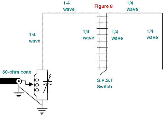
I tried the antenna on 20 meters with a quarter-wave phasing line made out of 300-ohm parallel transmission line. Results were very disappointing, even when the phasing line was placed in the horizontal plane.
Simulations on EZNEC showed that the horizontal line between the two vertical radiators also acts as an antenna, not only as a feedline. This gives the quarter-wave phasing line something more to interact with.
The quarter-wave phasing line is also placed at a high impedance point, and it may be that the 300-ohm line didn’t present an acceptable match to the system. I’m not 100 percent sure about the exact reason for the problem, but the up-to-date version of EZNEC also agrees that the idea is definitely not sound.
Another Option
After going through all of the above, I felt there was definitely room for improvement.
Being unable to change the radiation direction of the Half-Square antenna was a big drawback. I also wasn’t very happy with the depth of the off-axes nulls. Although 13-dB suppression of an unwanted signal is definitely better than nothing, an additional 10-odd dB would be very nice to have. It was time to engage the brain a bit before I switched the soldering iron on for the next round of experimentation.
Radiation by the horizontal line is probably the cause of the lack of depth in the off-axes nulls. If this horizontal radiation can be reduced, the radiation pattern will definitely improve.
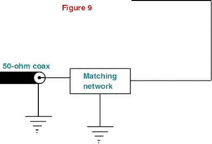
In the Winter 1992 Issue of Communications Quarterly, Henry Elwell, N4UH described a short, vertically polarized antenna in which the horizontal radiation was to a big extent canceled out. The total length of the antenna is a half wavelength. He called his baby the Lazy U antenna (Figure 9).4
Phased Lazy U’s
I figured that if two of these antennas were spaced a half wavelength apart, it might just provide a solution to my problem (Figure 10). “Conventional” means could be used to feed them, which would enable the radiation direction to be easily changed.
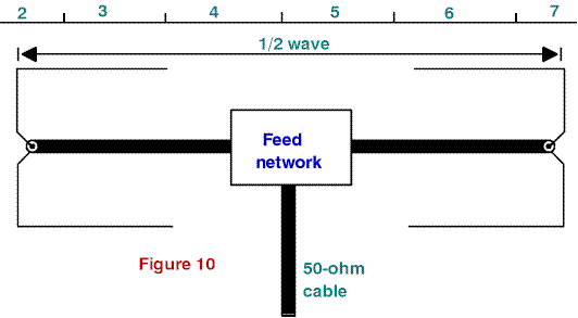
To fit on the 12-meter masts, and for operation on 40 meters, the vertical section of each Lazy U is 10 meters long with the lower ends 2 meters above the ground. The horizontal sections are each 5.2 meters long. The antennas are current-fed at the centers of the vertical elements. (This is the same method by which a dipole is “normally” fed.) Little time was lost in feeding this idea to EZNEC.
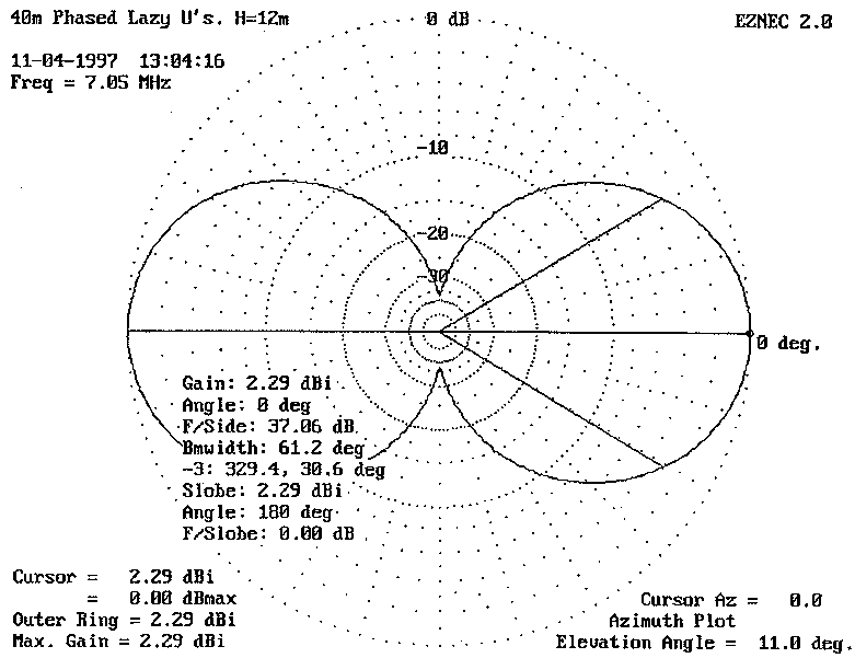
From Figure 11, you can clearly see the improvement in the nulls. As a bonus, the gain improved a little when compared to the Half Square antenna of Figure 6.
Feeding the Array
The impedance of a single Lazy U is close enough to 50 ohms to keep any transmitter happy. Ensure that each antenna presents a proper match before connecting them in an array.
Equal lengths of 50-ohm coax are used between the two Lazy U’s and the phasing transformer. The power to the two Lazy U’s is equally divided by the two bifilar windings of the RF transformer (Figure 12). Ferrite toroids, such as those normally used as balun cores, can be used for the transformer. The winding that connects the feedline from the transceiver is also used to match the 25 ohms presented by the parallel connected Lazy U’s to 50 ohms by means of the 1.414:1 turns ratio.
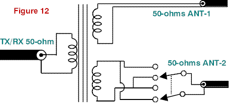
The radiation direction is rotated 90 degrees by changing the phase of the feed of one of the Lazy U’s by 180 degrees.
Proof of the Pudding
Unfortunately, my work load has increased to such proportions that it will be some time before I will be able to put up Phased Lazy U’s and perform some serious evaluations. However, the computer simulations are so promising that I felt the idea had to be shared with other enthusiasts. Hopefully, things will improve soon enough so this antenna won’t stay a computer simulation for too long.
Operation on Other Bands
According to the computer simulations, the Phased Lazy U’s performance as an efficient DX antenna on 80 meters, or even 160 meters, should be hard to beat, if you’ve got the real estate to fit it in!
Last Thoughts
It will be interesting to make use of four Lazy U’s in a four-square array. The high radiation efficiency of the individual radiators coupled to the selectable radiation direction should prove to be a winner on the low bands.
For low-band DXing, an efficient transmitting antenna system (Phased Lazy U’s) represents 50 percent of the requirement for success. The other 50 percent is made up of operator skill and the use of enough transmitting power to ensure an adequate signal-to-noise ratio at the receiving station. In general, running barefoot isn’t good enough for serious low-band SSB DXing.
Conclusion
Despite all the claims in the amateur press over the years, the Half-Square antenna is not the ultimate solution to all your communications needs. At 14-MHz and higher, a tribander at the same height definitely outperforms the Half-Square antenna by a fair margin.
On 7 MHz and lower, the Half-Square antenna has a distinct advantage over a small beam or dipole used at less than a third of a wavelength above ground. The directivity and off-axes nulls also count in its favor. The antenna is also simple to construct.
Phased Lazy U’s are not as simple to erect as the Half-Square antenna, but the ability to change the radiation direction by simple means, as well as the deeper off-axes nulls and marginally higher gain, ensures better performance from this DX antenna when compared to the Half-Square antenna or a low dipole.
The fact that none of the above-mentioned antennas requires an extensive ground system counts for a lot of points in my book.
References
1. Jerrold A. Swank, W8HXR, “Rotate the Bobtail Curtain,” 73, May 1985, pages 48, 49.
2. F.C. Smith, GW2DDX, “Variations on the Vertical,” Practical Wireless, July 1987, page 26.
3. Brian Austin, ZS6BKW, “An Updated Version of G5RV Multiband Dipole,” Radio ZS, June 1985, page 58, 59.
4. Henry Elwell, N4UH, “The 160-meter Semi Vertical: A Case History,” Communications Quarterly, Winter 1992, pages 81-93.
Originally posted on the AntennaX Online Magazine by Hannes Coetzee, ZS6BZP
Last Updated : 30th April 2024


