The J-pole antenna has been around for many years and is a very good antenna for amateur use. It is a form of the Zepp antenna, and Zepp is an abbreviation for Zeppelin, as in lighter than air airship. The basic antenna is a half-wavelength antenna fed by a quarter-wave-matching stub. It has a low angle of radiation and can be matched to coaxial feedlines fairly easily. Most of the J-poles are made for the two-meter band but they also have been built for 50, 222, and 440 MHz. I’ve heard of one built for the ten-meter band though and apparently worked very well. It was over 16 feet (4.9 m) tall though.
One of the hams I talk to regularly commutes from his farm about 70 miles into town and we talk on two meters until he gets into range for a 440 repeater. His mobile antenna is barely adequate for about 30 miles though while I have worked back into town from 65 miles out. Both of us use a 5-watt HT and the only difference is the antenna. So I decided to see about coming up with a better antenna for his mobile. Some gain is desirable, since he is only running a 5-watt HT. Since there are low hanging tree branches to contend with on his route, a sturdy antenna was essential.
The J-Pole Antenna - Figure 1
The best antenna I could come up with was the J-pole. By building it out of 1/2-inch (1.27 cm) copper pipe it would be less likely to be damaged by small branches and other foliage hanging over the road in and out of his farm.
Figure 1 is the basic diagram of the 6dB J-pole. The feed point is determined by tapping up on the 1/4 stub with the center conductor and the shield is tapped up on the 1/4-wavelength section, just below the bottom 1/2-wavelength section. This particular version is a stacked collinear antenna with approximately 6-dB gain. It is also at ground potential, which is a plus for lighting protection.
As you can see, the antenna is made up of two 1/2-wave sections connected by a 1/2-wavelength phasing section. This gives the correct phasing for the two sections in order to get the 6dB gain ability of this antenna .
The J-Pole Antenna - Figure 2
Figure 2 is the diagram for a 3dB J-pole. As you can see, this is a simpler antenna and less costly to construct. Even though the antenna is simple, it does perform well. Being omnidirectional, it gives good coverage for any repeater in range of your antenna and also can alert you to band openings.
The J-Pole Antenna - Figure 3
Figure 3 shows the method of feedline connection. By sliding the center conductor and the coax braid up and down the matching section, you can get the SWR down to minimum fairly easily. Then you can solder the connections in place or use whatever other suitable method to permanently connect the feedline to the antenna. However, do not use hose clamps or any other mechanical methods of connection to the antenna. If you do, corrosion will take place and the signal will deteriorate. Soldering the connection is probably the best way.
The J-Pole Antenna - Figure 4
Figure 4 demonstrates a method of mounting this mobile antenna with use of a spring to add flex to cope with those overhanging obstacles.
The J-Pole Antenna - Figure 5
For maximum performance, the use of a 4:1 balun will allow the match to be even easier set to 1:1 VSWR. Using 50 ohm feed line will give you a 200-ohm balun and the method of adjustment is the same as with coax. Figure J-5 illustrates the construction of a 4:1 balun using 50-ohm cable such as RG-58. Using the balun will allow the maximum efficiency of the system to be realized.
My friend’s test results of this configuration will be discussed in a followup article next month.
One Month Later - The J-Pole Antenna, Part 2
Last month, we described this particular J-Pole project for WD5EXQ who needed a better performing antenna on his truck for use between the city and his farm, some 80 miles distance. Before this new J-Pole configuration, Jack could only reach about 30 miles out. During Part 1 of this article, we were still in the eXperimenting stage—now, we have the finished result for those with similar problems, or just find the J-Pole an interesting antenna subject. Editor’s Note: Jack Brown, WD5EXQ is antenneX’s very first subscriber from way back in 1988. Consequently, Jack has been given a lifetime subscription for his courage to be first!
When the antenna was finished mechanically, the matching network was installed after several days of testing three common methods.
These methods were:
200-ohm balanced feed, with a 4:1 balun.
50-ohm balanced feed with a 1:1 balun
50-ohm unbalanced feed.
The 50-ohm unbalanced feed was the one finally used for several reasons: it’s mechanically simple, easy to tune for 1:1 VSWR, and very broad band between 1.5:1 points. The 200-ohm feed was almost as flat as the 50-ohm unbalanced method, with 1.5 to 1 at 430 and 450 MHz. We had the most problem with the 50-ohm balanced feed, as I could not find the 1:1 point. The lowest I could get was 1.5 to 1 at the lowest point, with the VSWR rising to 2:1 only 5 MHz on each side of the low point.
However, the unbalanced feed was the easiest to tune and had a very wide low VSWR range. The VSWR from 430 MHz to 450 MHz was 1:1, no doubt in part due to the use of 1/2-inch (1.27cm) copper tubing for the antenna. There were other methods suggested, but due to the mechanical considerations, they were not used. I suspect they would done as well, if I had the time to experiment with them.
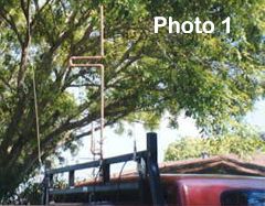
The J-Pole Antenna - Photo 1
The Installation on WD5EXQ’s truck was done with tie wraps, as he was going to make a custom mount when he got home. Photo 1 shows the installation. The whip to the left is his two-meter antenna and the small whip to the right is a 1/4-wave 440 whip.
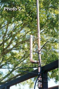
The J-Pole Antenna - Photo 2
Photo 2 shows the feed point and how the coax was tied down to the mast and the mast mounted to the vertical upright on the headache rack. This will be replaced later with a custom mount WD5EXQ will construct just for this antenna.
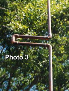
The J-Pole Antenna - Photo 3
Photo 3 displays the phasing section between the two antenna sections.
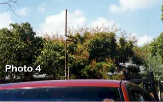
The J-Pole Antenna - Photo 4
Photo 4 shows the radiating part of the antenna is above the rooftop. To further explain, the matching section does not radiate any significant amount, so as you can see, the matching section sticks up above the roof so the antenna itself is above the roof several more inches, (several centimeters). This can limit the amount of RF absorbed by the roof.
The result of this antenna work was an increase in range from about 30 to 70 miles, as the route WD5EXQ takes to go home which is about 80 miles from my location in the city. This was a significant increase in range for a 5-watt ht. At the extreme end of the range, the repeater simply dropped out. I believe if we had replaced the old RG-58 A/U already installed with some new RG-8X, there would be another increase in range. Not much probably, but enough to maybe get him into his front yard before the repeater drops out.
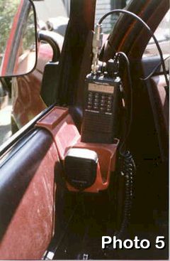
The J-Pole Antenna - Photo 5
Photo 5 is a view of the installation in the truck. The terrain here is very flat, except in the vicinity of Jack’s house where there are a lot of rolling hills. So long ranges can be expected on most of the VHF and UHF repeaters around here, depending on the variables connected with repeater installation, height and feedlines, antennas gain, and the other things that affect repeater ranges.
All of the hard work put into this antenna was worth it, because it performed as expected during eXperimentation in Part 1. The mechanical strength is adequate for hitting small branches that had mangled lesser antennas. With the installation of the custom mount for the antenna, the antenna can be lowered and raised from inside the truck. Jack’s now a happy trucker!
Originally posted on the AntennaX Online Magazine by Jack Brown, WD5EXQ and Richard Morrow, K5CNF