Folded Unipole
The principal pioneer in the use of folded unipole antennas in AM radio broadcasting was John Mullaney, W3NGJ (SK). His first applications were in the 1950s. He wrote several articles for Broadcast Engineering magazine. In the 1970s he had a computer program written by Dr. Jerry Raines for designing unipoles. This is still a proprietary program owned by Mullaney Engineering, Inc., but they sold me a copy. It really works.
Acts Taller than it is
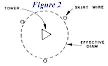
When a 3-wire folded unipole is installed on a thin tower or mast, it makes the antenna perform as if it has a much larger diameter. This decreases the length to diameter ratio which results in better bandwidth and it also decreases the velocity within the antenna which makes the antenna appear to be slightly taller. It is assumed by many that the velocity within a thin tower is about 95%. Measurements by myself and others indicate that the velocity within a typical folded unipole is from 82 to 84%. This means that you could reduce your antenna height about 10 or 12% for the same performance.
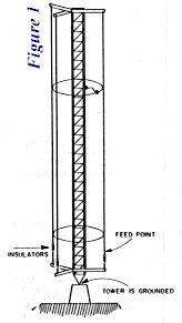
Early folded unipoles for AM broadcasting utilized galvanized steel guy wire for the folds. However, in some cases this can cause a decrease in efficiency. Copper-clad steel wire is the best choice, because skin effect causes most of the RF current to be in the copper jacket and the steel core prevents stretching. In a folded unipole antenna the tower is grounded, rather than being insulated. This allows the installation of VHF, UHF and beam antennas on the tower.
For Tight Spaces
Diplexing two or more AM broadcast stations into a single antenna is becoming more popular due to the price of real estate and other factors. This is done by having a separate set of skirt wires for each frequency and tuning each set for a particular frequency. What this means for a ham is that he can multiband a folded unipole antenna by the same method. For example, you could have separate skirt wires for 160, 80 and 40 meters. Obviously, the jumpers for 160 are going to be higher than 80 and the 80 jumpers are going to be higher than the 40 jumpers. But you should be able to get near 50 ohms on each of them. Bear in mind that they will interact with each other. If you don’t mind running out to the tower when you change bands, you can get by with a single capacitor and tweak it for lowest SWR, but if you use a separate capacitor for each band you could stay inside the shack on a cold winter night.
Watch for Pitfalls
While we have had complete success with vertical antennas, there are pitfalls from which we have developed some rules of thumb:
- If the tower is more than about 3/8 wave tall, the impedance can become almost impossible to deal with. This is because the unipole is a transmission line type antenna and as the height approaches 1/2 wave tall and beyond it has a bandwidth that is extremely narrow and very high reactance. The fix for this is to place insulators in the top ends of the skirt wires rather than attaching them to the tower. The computer program does not include this geometry, so it becomes trial and error.
- Speaking of computer programs, most antenna modeling programs used by hams are based on the NBC2 core. This core has difficulty in modeling antennas made of wires with greatly differing diameters (more than about 10:1) . When you place a thin wire (or wires) near a tower with a much greater effective diameter, NEC2 has problems. You might model the tower as a bunch of wires forming a cylinder or triangle, but it may push the limit of your program. Programs written around the NEC4 core have no problem with large d/d (diameter to diameter) ratios, however, they are not commonly available. (Editor’s note: See this month’s article “Software Review: NEC4WIN95” by L.B. Cebik, W4RNL)
- For some reason, folded unipole antennas with electrical heights of about 105 to 115 degrees have extremely broad bandwidth.
- Electrically short antennas (down to about 1/16 wavelength) can be built to provide 50 ohms resistance, but bandwidth is normally very narrow. Top hat loading (including an HF Yagi beam antenna) can greatly help this.
- You can build a stand alone folded unipole or build one on your tower with the beam and other antennas on it.
- Don’t space the wires too close to the tower. The shunt capacitance between them will negate any advantages. We have built broadcast antennas with spacings from 30″ to 60″, but for amateur use 16″ to 18″ is fully adequate. If you place the wires only 3″ or 4″ away from your tower, you may be disappointed.
- To prevent the wires from flailing around during high winds, use insulated standoff insulators at intervals of no greater than about 25 feet. Fiberglass rods are good, but PVC pipe can also be used.
- Install insulators at the bottom ends of the wires. Tension them with turnbuckles. Connect the bottom ends of the wires above the insulators with a commoning ring of wire or copper tubing. This ring will be the feed point of the antenna.
- Although the folded unipole is not as ground dependent as a series fed antenna, you still must have some kind of ground. If you use wire radials make them as long as possible and put in as many as possible. If you bury the wires, be aware that the soil permittivity (or dielectric constant) decreases the velocity by a factor of typically 3 or 4. A quarter wavelength of wire in the ground will become about 3/4 to one wavelength long, so don’t worry about making them exact lengths. Just put in as many as possible.
Detune and Disappear!
Finally, the folded unipole can be used to detune a tower (or any other metallic object) making it effectively disappear at a specific frequency. This could provide an article for a future issue of antenneX.
Originally posted on the AntennaX Online Magazine by Ron Nott, K5YNR
Last Updated : 22nd April 2024