Broadband Antennas
Some Examples
One of the limitations most hams have is the inescapable fact that our antennas are of relatively narrow bandwidth. This is particularly noticeable on the lower bands, 160, 80 and 40 meters which suffer rather badly from narrow bandwidth. The problem becomes very discouraging when you want to operate on 3.645 MHz in order to check in on the “Tri-State Ancient Order of Ex-Spark Operators,” chase DX on 3.510, and hop up to 3.975.1 MHz for the meeting of the “Royal Order of the Windbag and Blowhard” net. Your antenna usually says “HIGH VSWR!!” and your solid state transmitter balks at the high VSWR and shuts down. Unless you have a matching network of some type, forget wide band excursions on 75/80 meters.
40 meters is almost as bad, and 160 meters is terrible. So what to do in cases like this?? Things can get a bit sticky unless you have an automatic antenna coupler located at the feedpoint of an inverted L with a horizontal length of at least 1/2 wavelength or longer at your lowest frequency. So now what? To come up with a variety of answers, let’s examine some examples of broadband antennas that have been used successfully, both old and new designs.
Examine Some Types
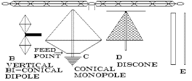
In Figure 1 we have several examples that have been around for years.
Fat Dipole
Figure 1 Diagram A is the “fat dipole” which is a dipole made up of wire elements separated by insulated spreaders in an “X” configuration. The elements of the dipole then act as a conductor with a diameter equal to the size of the spreaders. This will increase the bandwidth of the antenna a good amount, and also will make adjustments in overall length a necessary action, because the apparent increase in diameter will cause an actual increase in the antenna’s capacity to ground.
To tune the fat dipole, the usual practice is to have 75% of each half of the antenna made up of the fat element and the remaining 25% of each half as a single length of wire that can be adjusted for resonance at a center frequency. This is easier than trying to cut all of the individual lengths of wire to tune the antenna.
Bi-Conical Dipole
Figure 1 Diagram B is a variation of this same theme. This type of antenna is usually seen at airports, and is used to cover the entire VHF aircraft band which is greater than 10 MHz.
Conical Monopole
Figure 1 Diagram C is of the conical monopole, which is a vertical with a cage of wires that run from the top to a circular spreader at a distance approximately 2/3 of the way from the top and then to a common ring at the base where the center conductor of the coaxial feedline is connected. The center monopole support has all of the wires that make up the cage tied to the top, and the bottom of the pole is solidly grounded.
This antenna, when made for a lower cutoff frequency of 40 meters, is capable of covering from 40 meters to nearly 25 MHz. Impedance variations from the feedpoint impedance of 50 ohms are not supposed to be significant. The military uses these antennas a lot and in pictures of Navy battleships, monopoles can be seen on the bows.
Discone
Figure 1 Diagram D is the discone antenna, which has been around a long time being described in the February 1946 Proceedings of the I.R.E. There have been many construction articles in the ham magazines telling how to make discones on Frequency ranges from 3.5 MHz to 1300 MHz. SWR stays under 2:1 for nearly the entire bandwidth the antenna is designed for. A discone was being sold by Radio Shack capable of receiving from 25-1300 MHz and transmitting on 144 to 1296 MHz with a 200 watt power handling capability. The polarization is horizontal as the top disk is the radiating element, and the cone is the ground plane which the radiating element is working against.
A practical example of this effect can be shown in the construction of a 75 meter vertical using 3 inch diameter downspout with a physical length of 1/8 wavelength. Base loading was used to resonate the antenna as a 1/4 wave vertical. With a center frequency of 3.8 MHz, the VSWR was 1.9:1 at 3.550 MHz and 1.2:1 at 4.00 MHz. The base loading and matching coil was made of #10 wire on a 6 inch diameter form. After a high wind destroyed this antenna, it was replaced by one made of 10-foot TV mast sections. The same coil was used for matching and loading.
This antenna had a bandwidth of half of the large diameter antenna, with a VSWR of 2:1 at 3.65 MHz and 3.95 MHz. Tuning was more critical and the tap for antenna matching impedance had to be moved. After several months, this antenna was replaced by more 3-inch downspout soldered together like the first one had been and the original bandwidth and tuning connections were restored.
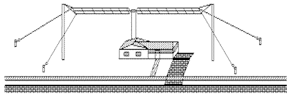
The Bigger the Better
In the days of spark and very long wavelengths, the theory was that the bigger the antenna was, the better it worked. The antenna in Figure 2 was very common and was either fed at the end or in the middle. Usually these antennas were anywhere from 100 feet and up and as long as the real estate space allowed. By nature, these antennas would be broadband since the spark signal was a broadband signal. Often the antenna would determine the most efficient frequency, because the natural resonant frequency of the antenna and ground system would be the frequency that radiated best.
Make Guy Wires Part of the Antenna
There was meant to be a Figure 3 but I am afraid that it was missing in the Original antennaX website download. There are stabilizing guy ropes at the corners of the antenna to keep it from twisting in the wind. These guy ropes can also be made a part of the antenna by using wire instead of non-conducting rope. This is illustrated in Figure 5 where ends of the stabilizing guys meet the insulators attached to the ground stakes. The use of this type of antenna would allow the complete coverage of 75 meters with good efficiency and low VSWR. This antenna would do best if it were fed with a balanced feedline of some sort, possibly 75 ohm twinlead for example.
Figure 4 is a multiple conductor multiple frequency dipole. This antenna type has been around in various forms for many years as a fan dipole or bowtie. It can be a beast to tune as altering any of the element lengths will change the tuning of the rest of the antenna. It is effective, and does work well when it is finally tuned up. The illustration is of only one form—there are many variations. Again, the use of balanced feedline is recommended.
Figure 5 is pretty much self-explanatory, as it shows a typical installation of both types of dipoles. The biggest problem with the multiple conductor antenna is that it can be a real terror to put up when there are any trees involved. Keeping the branches from snagging the numerous wires can be a real tricky effort. The weight of all that copper can get heavier in windy conditions, so construction and hanging of such antenna needs to be done with much forethought and care.
The Fan Vertical
Another variation is the fan vertical, shown in Figure 6. This is essentially a multiple conductor vertical with each conductor cut to a different frequency. The radial system can be done in the same way, with radials cut to match a vertical wire. By using a number of 1/4 wavelength wires, a number of frequencies can be covered.
As you can see, antenna can be broadbanded through the use of multiple conductors or large diameter elements in the construction of an antenna. These methods have been well-proven through the years of use, and should give anyone food for thought when contemplating the construction of a broadband antenna.
Originally posted on the AntennaX Online Magazine by Richard Morrow, K5CNF
Last Updated : 6th March 2024