Folding the Short ZL Special For Portable Operation
Construction Details
The element lengths for 28.5 MHz are as follows:
Driven element length is : 12.3 feet
Reflector is : 13.0 feet
Boom length is : 3.6 feet
So, if the boom could be folded, it would only be 1.8 feet long and the elements would fold down to just slightly over 6 feet. If you folded the boom back on itself, and folded the elements parallel to the boom it would very compact package, indeed. One that could be easily carried on the top of the smallest subcompact car.
Figure 1 shows the overall modifications needed to the wooden frame used for the ZL Special. The boom is cut in half at the mast clamp and a hinge is installed on the top of the boom. A common screen door latch is used to hold the boom and mast together. The mast clamp will add more strength to the boom when the antenna is clamped to the mast.
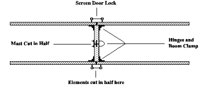
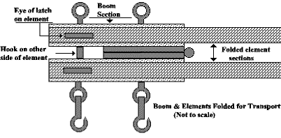
Figure 2 shows the details of how this is done.
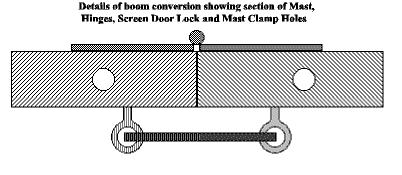
Figure 3 shows the boom assembly folded to 90 degrees.
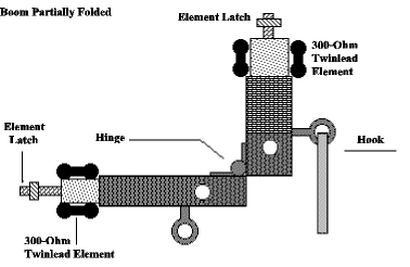
Each element support is made up of two lengths of 1″ x 2″, with the 300-ohm twin lead taped or glued to the 1″ sides of the support. Remember, the wood needs to be weatherproofed in some manner for weather protection. The L brackets that fasten the elements to the boom are replaced by small door hinges. The elements are held in the operating position by a screen door latch, as shown in Figure 4.
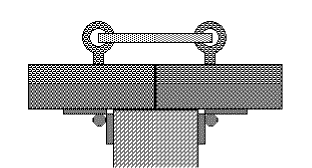
There is not a lot of strength needed to keep either the boom or the elements in their operating position, so the screen door hook type latch will do very well. It is best to buy the type of latch with the spring loaded lock that has to be slid back to either unlock or lock the latch. This would be most likely the type of latch to use on the element support because they will be prone to flopping around in a breeze. At each hinge point you need to have enough slack in the twin lead to allow everything to fold without putting the twin lead in a bind.
Figure 5 shows the folding sequence. Diagram A is the antenna before folding. Diagram B displays the boom folded flat against the bottom of the other half of the boom and Diagram C is with the elements folded flat against the boom.
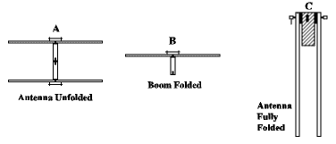
Figure 6 shows the folded antenna. This results in a very small package, less than 7 feet long and less than 1/2 feet across. A 20-meter version would be twice as long and not much wider across.
The materials used to construct a 14.0 MHz. version must be larger to deal with a boom length of 7 1/4 feet, element lengths of 24.5 feet and 26 feet for the driven element and reflector. Feedline can be 75-ohm twin lead or 75-ohm coax with a 1:1 balun. A low power antenna coupler should be used to take care of any matching problems that might occur due to feeding a 72-ohm cable with a 50 ohm transmitter.
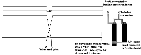
Figure 7 shows a detailed diagram of how to wire the elements and where to hook the feedline. Figure 7 also shows how to make the balun and wire the elements. The balun should be made out of the same coax used for feedline so the velocity factor will be constant. Otherwise the balun will not work correctly.
Calibration Formulas
The formula for the correct length of the coax that makes up the balun is:
2952 X VF/F(MHz) = S
Where VF is the velocity factor of the coax and S is length in inches.
The elements are made up of 300-ohm twin lead. Their length is calculated from the following formulas:
Driven element = 351/F(MHz)
Reflector = 351/F(MHz) X 1.06
Twin Lead is also used to tie the two elements together twisting it one-half turn between the elements to get the 180 degree phase shift.
More Gain
If the spacing between the elements is increased to .125 wavelength, a little more gain is realized, enough to make it worthwhile. The boom length would be 4.1 feet instead of 3.6 feet.
Increase Phase Shift
Increasing the boom length to 4.1 feet will also increase the phase shift between the two elements to 233 degrees which is where the unidirectional characteristics come in. This array is a phased array and is why it is directional. The “reflector” is not a reflector at all, but the other element of a phased array, not unlike the W8JK array.
Broadband
The difference in length between the first element and the second contributes to the broadband characteristics of this array, not to the directivity. It works though, so don’t fix it by changing anything as far as the elements are concerned.
Unidirectional Array
However, if the antenna is constructed as an W8JK array, and fed in the manner of the ZL special, instead at the middle of the array, an interesting possibility arises.
Since the original JK array was a broadband antenna and was capable of covering from 20 meters to 10 meters, it would be possible to make an array that would be unidirectional and cover the same frequency range. It would not have as much gain as a three-element YAGI, but more than a two-element YAGI.
By constructing an array for 20 meters using telescoping aluminum tubing with 1/8 wavelength spacing on 20 meters, an array to cover from 14 MHz to 30 MHz with good gain could be realized. The impedance of the antenna would change and also would vary with frequency. So, the use of an antenna coupler and a broadband balun would be required, unless twinlead of some sort was used. This antenna can also be constructed with one element slightly longer than the other, which will broaden the bandwidth in the manner of the ZL Special.
Some More Gain Here
The use of full 1/2 wave sized elements on 20 meters will allow additional gain to be realized on ten meters as the front and rear driven elements would then be 2 full wave length elements. Center feeding a full wave dipole element makes it a collinear array consisting of two half-wave elements fed in phase resulting in about 1.8 dB gain. This amount of gain, plus the gain resulting from the phase difference between the front and rear elements of the array adds up to a very noticeable amount.
Telescoping Elements
Aluminum tubing can be found in sizes that allow elements to be made that will telescope inside of each other. This will allow the elements to be reduced in length for transport. For an antenna of the dimensions that a 20 meter array, the boom would have to be increased in size to a 2 x 4. The supports for the aluminum elements would also have to be scaled up accordingly.
The increase in spacing of the elements as the frequency is increased from 14 to 28 MHz results in the phase shift between the elements increasing from 233.46 degrees to 284.2. However, since the phase relationships between the elements remain the same, the pattern does not change significantly, but there is an increase in gain on the higher bands.
Stack – Even More Gain
The monoband ZL Special, either the shortened version or the full sized one can be stacked with a significant increase in gain. Spacing is 1/4 wavelength for maximum gain. Figure 8 is an example of this type of array. Having an array of this type either stacked or not will enable you to have a good signal from a portable location.
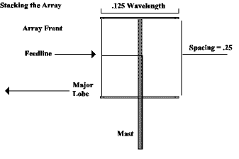
Figure 9 displays a JK Array fed st the front instear of the middle (without the boom for clarity).

If you use aluminum tubing and make the elements telescoping, you will be able to collapse the elements very short for transport. By scratching marks on the elements will help speed up the set up. When setting up the antenna on site, just extend each element until each scratch mark lines up appropriately. Unfold the mast and element supports, clamp the boom to the mast, hook up the feed line, raise the antenna and VOILA!
No On-Site Tuning
A definite advantage of this kind of antenna over the YAGI is that the YAGI needs on-site tuning. With the portable beam, all of the tuning was done when the elements were cut to frequency. There is no antenna-mounted matching system to be tuned on site and with a broadband balun for the multiband version, the use of an antenna coupler should take care of any matching problems.
The stacked version will need a balun as well as a coupler to take care any impedance problems that exist. No calculations have been done concerning the impedance of such an array.
You Can Do It
The ideas presented here should be sufficient information for anyone wanting to build a portable beam. Construction techniques can vary as well as materials, but as long as the concepts and formulas are followed, there should be no problem with this type of antenna. It’s convenient to transport, easy to erect and works well!
Formulas
Shortened ZL Special
Driven” element = 351/F(MHz)
Reflector”element = 351/F(MHz) X1.06
1/4 wave balun 2952 x VF/F(MHz) = S (length in inches)
VF is coax velocity factor.
Dipole element lengths for non ZL Special array:
468/F(MHz)
Originally posted on the AntennaX Online Magazine by Richard Morrow, K5CNF
Last Updated : 9th March 2024

