
Build this Low Cost High Quality Frequency Standard
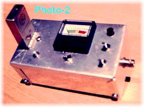
If you work with Ham or Commercial radio equipment, HF through SUHF frequencies, there will always come that point when you ask what is the correct frequency? “Can I trust my $100 frequency counter readings?” “Is the digital display on my transceiver accurate?” What is needed to provide the answers to these and other questions, with regard to frequency accuracy, is a known accurate Frequency Standard on your test bench! The frequency standard described here borrows a unique bit of old, but accurate, communications technology from the GE Master II series of FM transceivers, a small handful of parts and an enclosure for this very useful piece of RF test equipment. The unit constructed for this article is shown in Photo-1. An old outdated piece of test equipment provides an excellent enclosure for this project. You may select most any cabinet that will fill your needs. You should use a metal enclosure for maximum shielding however. A Bud “Mini Box” as shown in Photo-2 will also provide an excellent enclosure. This case was used in the construction of a similar project.
Just What is a Frequency Standard?
A Frequency Standard, of this type, is a voltage and temperature compensated crystal oscillator usually operating on a standard frequency such as 100 KHz, 1 or 10 MHz to mention several of the most common. If, however, you require a different standard frequency for your needs, the project shown here will provide you with frequency coverage from approximately 4 to 20 MHz.
Most of us with even a minimal amount of communications experience are aware of the accuracy available through the use of a crystal oscillator as the frequency determining element used in our receiver, transmitter or hwsp-2.jpg (14123 bytes)frequency counter for example. Crystal oscillators provide the standard frequency for the phase locked loop circuits within all of the newer transceivers on the market today. Phase Lock Loop circuits rely on just one single crystal oscillator to control all of the frequencies generated within your rig. If this one “ROCK” (an old expression for a crystal element which is made from quartz) is off frequency or is drifting up and down with temperature and voltage changes, your entire communications system will move right along with it on both transmit as well as receive!
Developing Your Standard
The idea for this frequency standard came along after a GE Master II “ICOM” (Integrated Circuit Oscillator Module) test set was constructed a few years ago (Photo-2) to allow the test and frequency adjustment of ICOMs, as used in older GE Master II transceivers. Many of these have been converted to provide excellent Amateur Radio FM repeater systems. This test set has been very useful for adjusting frequency and testing the ICOMs after a crystal change without having the rather large, bullet proof, Master II transceiver hooked up and running on the bench to do so.
See Photo 3. Over a period of time it was noticed just how stable this temperature and voltage stabilized module was in comparison with WWV standard frequency broadcasts. It was then decided to repackage the same circuit design, with a few additional features, into the enclosure shown in Photo-1. The cabinet was salvaged from the junk pile and was of little value in this day and age of close tolerance frequency applications. It even used those little glass bottles with a small light turned on inside each one!

In the schematic diagram shown below you will note the ICOM is shown as a block with six connections going to it. The output from the ICOM (Pin-3) is connected to buffer IC U-1 through C-9 and limiting zener diode D-1. The output from U1-2 feeds the output buffer U1-9 and decade counter input U2-1. The out from U2 is buffered by U1-5 and drives the second decade counter U3. Its output drives the input of U1-3. The resulting standard frequencies are 10 MHz, 1 MHz and 100 KHz in this example and are available at U1 pins 8, 6 and 4. The ability for this generator to provide additional frequencies will be discussed in detail as we cover the construction of this project.
Icom’s
There are three different ICOM types available for use in the old GE (now GE/Ericsson) Master II series radios. Each contains an integrated Colpitts oscillator with two of the three types containing internal, wide range, temperature compensation. These ICOMs are called out, as labeled on top of the case, EC-ICOM, 5C-ICOM and 2C-ICOM. The type labeled EC-ICOM has a more limited temperature range from 0 to 55 degrees centigrade. This temperature range however will cover most any bench type requirement and can be used with the addition of just two resistors. The 2C-ICOM is the preferred type but both this ICOM and its matching crystal will come at a much higher cost. The EC or 5C-ICOM is the most practical choice.
The 5C unit contains an oscillator temperature compensated to within 5 parts per million (.0005%). The 2C module is compensated to a tighter tolerance of only 2 parts per million (.0002%)! This stability is maintained over a temperature range from -40 to +70 degree C (-40 to +158 degrees F). The ICOM case has a hole in the top to allow easy adjustment of the oscillator frequency using a small screwdriver. ICOMs are available from various surplus radio outlets, swap meets and on communications sites on the Internet. (Please check the listings found on the antenneX “Useful Links” page).
Crystal Selection
In the circuit shown a 10 MHz crystal was specified as a standard to use. When ordering the crystal you specify a transmit operating frequency of 30 MHz as used on the GE Master II low band unit. This will provide you with a 10 MHz crystal. You may also ask for the crystal frequency you desire without a problem. I have found Bomar Crystals very cooperative in this area. This is a very common frequency to use and, as described, will also provide a 1 MHz and 100 KHz output as well. Other frequencies, within the range of these ICOM units, may also be selected. The decade counters that divide the 10 MHz frequency down to 1 and .1 MHz may also be configured to divide by two or by five if required. The ICOM used in this project will operate over a frequency range between 4 and 20 MHz. The crystals are available from several suppliers as shown in List-1.
CAUTION: For proper operation and stability you must acquire the exact crystal cut to match the GE ICOM it is to be used in. Do Not substitute a low cost “Computer Grade” crystal to take advantage of the savings. This will “Deep Six” the project before you begin! Specify the ICOM part number to the crystal manufacture when ordering.
Project Construction
Shown in Photo-1 (Top of this article) is the cabinet as salvaged from an old Measurements Corporation Model-111-B Crystal Calibrator set. It was fortunate the original switch functions and outputs were useable on this project. The original high voltage transformer was replaced with a 12 vdc / 300 ma “Wall Wart” called out in the parts list. As previously stated the enclosure used is not critical as long as it is of metal construction used to provide good shielding. The ICOM and the three IC sockets are mounted on a small piece of perf board as indicated. Keep your leads short but you need not go to the extreme. All critical frequency determining circuits are contained within the ICOM unit.
After construction you may find a short ground lead is required to prevent marker “Birdies” on your receiver. Due to the sharp edged square waves involved in the buffer and divider stages, the outputs are rich in harmonic content. A simple L-C or R-C filter can reduce these if desired for your application.
Test and Calibration
CAUTION: Do not install the ICs or the ICOM unit at this time. After completing construction and wiring check you are ready for the first power check. Apply power to the circuit. Using the schematic diagram shown in Figure-1check for +9 vdc* between ground and Pin-1 of the ICOM connector. Check for +4.5vdc between ground and Pin-2 of this connector (only needed if using the type EC ICOM). Next check for +5vdc between the VCC and Ground pins on the IC sockets. If all is well remove power and install the IC’s and your ICOM.
NOTE: If you have procured your ICOM but have not as yet obtained your “Standard Frequency” crystal you may use the crystal that is most probably included within the ICOM from its mobile radio service days just for test purposes. Its fundamental frequency will be marked on the crystal itself but is not of much importance, except for testing, at this point.
Connect your scope probe to Pin-3 of the ICOM socket. The ICOM output frequency should be seen at this point. Proceed to U1 Pin-2. This should be the same ICOM frequency at 4.5 volt TTL level. This signal may not be symmetrical at this point but will be after the first flip flop stage of U-2. Continue through the two decade counters U-2 and U-3 checking the following test points shown in Figure-2.
The frequencies shown in Figure-2 assume the use of a 10 MHz ICOM frequency followed by two decade dividers. Your frequencies will differ if you have selected a different fundamental frequency or divider network. If all is well it is time to calibrate your oscillator. If you are fortunate to have access to a high accuracy frequency counter or other standard please use this for your calibration. The majority of us will have to rely on the received frequencies of radio station WWV or WWVH. These stations are heard around the world on carrier frequencies of: 2.5, 5, 10, 15 and 20 MHz. Adjust the ICOM trimmer for a zero beat in comparison to the carrier frequency of station WWV. The use of an oscilloscope in conjunction with your “Standard Oscillator” and your receiver will greatly improve the ease and accuracy of this calibration.
As the new crystal you installed in the ICOM “Ages” over a period of time (a long slow process) your oscillator will become more stable with time but its frequency will drift slightly, in one direction, as it ages. Check your calibration frequently during the first several months of operation to be certain you are within tolerance. Adjust as required.
Figure 2 ~ Test Points
| Part Number | Quantity | Description | Comments |
|---|---|---|---|
| C-1, 2, 3, 4 | 4 | .01 uf / 50 v Cer Disc Cap | 5v Buss Decoupling |
| C-5, 6, 7, 8 | 4 | 4.7 uf Tantalum Cap / 15 v | VR-1, 2 Decoupling |
| C-9 | 1 | .001 uf / 50v Cer Disc Cap | |
| C-10 | 1 | 500 uf / 25 v Electrolytic Cap | |
| R-1, 2 | 2 | Resistor, ¼ watt, 1%, 10 K | Only for EC ICOM |
| R-3, 4 | 2 | Resistor, ¼ watt, 5%, 2.2 K | |
| R-5 | 1 | Resistor, ¼ watt, 5%, 51 ohm | |
| R-6 | 1 | Resistor, ¼ watt, 5%, 560 ohm | |
| D-1 | 1 | Diode, zener, 5.1 vdc | 1N4733 or equal |
| U-1 | 1 | IC, 7404, Hex Inverter | See text for substitutes |
| U-1, 2 | 2 | IC, 7490, Decade Counter | See text comments |
| VR-1 | 1 | IC, Voltage Reg. 9 vdc | 78L09 |
| VR-2 | 1 | IC, Voltage Reg. 5 vdc | 78M05 |
| SW-1 | 1 | Switch, rotary, 4Pos, NS | |
| J-1 | 1 | Connector, BNC | User Choice Item |
| J-2 | 1 | ICOM Conn. EH, 6-Pin | RSU 11929882 |
| ICOM | 1 | GE ICOM | SEE TEXT |
| SOCKET | 3 | 14 PIN DIP IC SOCKET | RS P/N 276-1999 |
| PWR SUP | 1 | 12 vdc, 250 ma | “WALL WART” TYPE |
| PC BOARD | 1 | TO MOUNT 3 IC’s + COMP | RS P/N 276-150 |
Using Your Frequency Standard
Over a period of time you will find many uses for your new standard. You will find in most cases the accuracy of a low cost frequency counter can be greatly improved by connecting this external standard oscillator in place of its internal oscillator. If you have two HF or VHF rigs with digital readouts it is often very annoying to be tuned to the same station with a different frequency displayed on each rig. Using “ONE” frequency standard, where possible, will have all of your equipment “Singing from the same Song Sheet”!
Using the 10 or 1 MHz or the 100 KHz output into any divider/counter combination you require will allow you to come up with almost any standard frequency needed. Although somewhat outdated TTL ICs were used in this design they were a practical choice at the time and were readily available in my “Junk Bin”! More up to date counters and buffers may be substituted as desired. High Speed Shottky or CMOS components may also be used. Please remember the buffered output, after frequency selector switch SW-1, is at TTL voltage levels through a 51-ohm resistor. This signal level may be too high a level for certain applications and should be “Padded Down” through a resistive divider. If the output signal is to low for a specific application an amplifier or voltage level shift stage may also be added. None of these suggested logic substitutions will have any effect on the stability of the GE ICOM control element.
*Note: Although the original GE ICOM design required +10 volts dc for its operation +9vdc is a practical voltage to use due to the availability of standard three terminal 9 volt regulators. Any well regulated voltage between + 9 and 12 vdc may be used.
List 1 – Crystal Suppliers
NOTE: (*) Indicates a positive personal experience with this company!
HyQ: (606) 283-5000 – USA
Cathodeon Crystals
Linton, Cambridgeshire England UK
List 2 ~ Parts List
| Part Number | Quantity | Description | Comments |
|---|---|---|---|
| C-1, 2, 3, 4 | 4 | .01 uf / 50 v Cer Disc Cap | 5v Buss Decoupling |
| C-5, 6, 7, 8 | 4 | 4.7 uf Tantalum Cap / 15 v | VR-1, 2 Decoupling |
| C-9 | 1 | .001 uf / 50v Cer Disc Cap | |
| C-10 | 1 | 500 uf / 25 v Electrolytic Cap | |
| R-1, 2 | 2 | Resistor, ¼ watt, 1%, 10 K | Only for EC ICOM |
| R-3, 4 | 2 | Resistor, ¼ watt, 5%, 2.2 K | |
| R-5 | 1 | Resistor, ¼ watt, 5%, 51 ohm | |
| R-6 | 1 | Resistor, ¼ watt, 5%, 560 ohm | |
| D-1 | 1 | Diode, zener, 5.1 vdc | 1N4733 or equal |
| U-1 | 1 | IC, 7404, Hex Inverter | See text for substitutes |
| U-1, 2 | 2 | IC, 7490, Decade Counter | See text comments |
| VR-1 | 1 | IC, Voltage Reg. 9 vdc | 78L09 |
| VR-2 | 1 | IC, Voltage Reg. 5 vdc | 78M05 |
| SW-1 | 1 | Switch, rotary, 4Pos, NS | |
| J-1 | 1 | Connector, BNC | User Choice Item |
| J-2 | 1 | ICOM Conn. EH, 6-Pin | RSU 11929882 |
| ICOM | 1 | GE ICOM | SEE TEXT |
| SOCKET | 3 | 14 PIN DIP IC SOCKET | RS P/N 276-1999 |
| PWR SUP | 1 | 12 vdc, 250 ma | “WALL WART” TYPE |
| PC BOARD | 1 | TO MOUNT 3 IC’s + COMP | RS P/N 276-150 |
Originally posted on the AntennaX Online Magazine by August Hoecker, W8MIA
Last Updated : 1st May 2024