The Effect of Height on a Simple Antenna


Nearly all of us from hams to shortwave listeners have been told the higher the antenna, the better the reception, or in the case of a ham, the better the transmission and reception. So, just how much does height control what our antennas do? In order to find out, suppose we use a simple dipole for 40 meters and see what it does as the height is increased in 1/4 wavelengths.
Figure 1 is the intended subject, a dipole cut for 7.150 MHz and despite what the drawing is labeled, it is located at 35 ft.
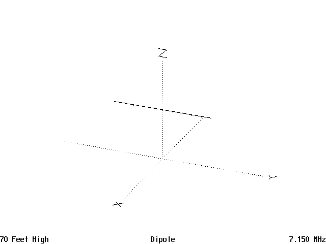
Figure 2 is the horizontal pattern with the antenna ends at 90° and 270°. This is where the pattern is at a null, off the ends of the antenna.
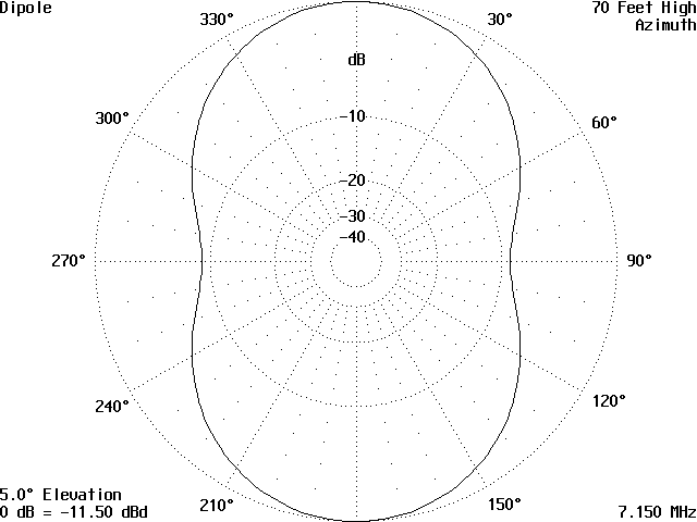
Figure 3 is the vertical pattern as viewed from a point broadside to the antenna, either directly in front or behind the antenna.
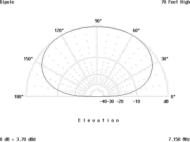
Figure 4 is the 3D view from slightly to the right front and above the antenna.
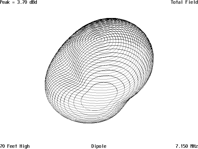
Figure 5 is the current distribution along the antenna and this does not change enough to concern us as the height is increased.
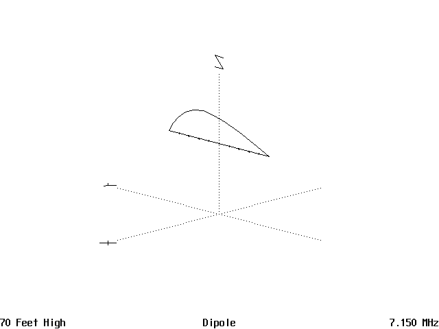
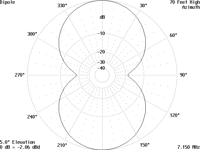
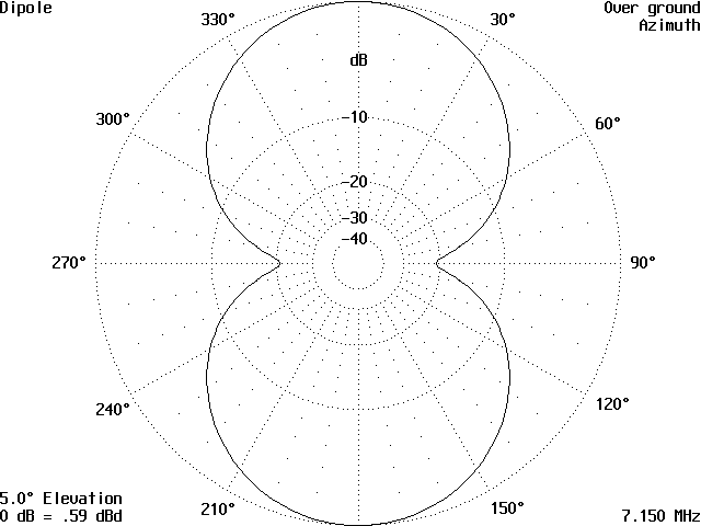
Figure 6 is the horizontal pattern taken at a measured height of 70 ft. and the nulls off of the end can be seen to get more pronounced as height is increased.
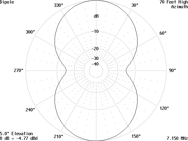
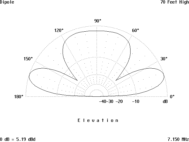
Figure 7 is the vertical pattern and this shows a definite lowering of the pattern and narrowing of the vertical lobes. The angle of radiation is down to about 25° and this is good for DX work.
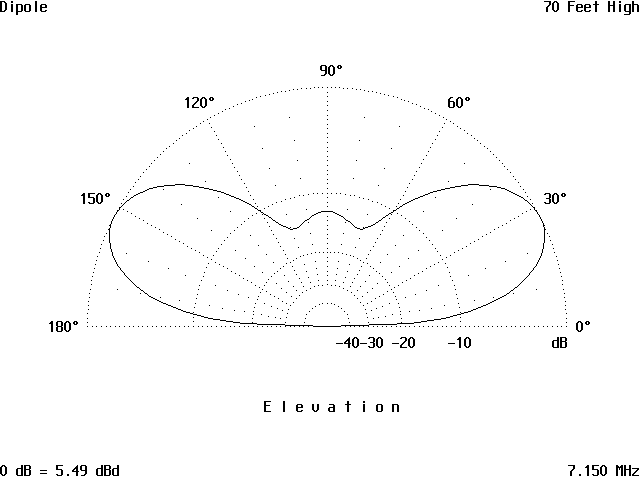
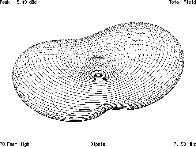
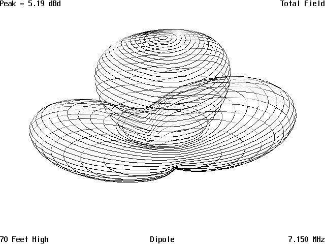
Figure 8 is the 3D presentation of the pattern. The squeezing in of the pattern off the ends of the antenna is noticeable as is the small peak directly over the center of the antenna.
Raising the antenna to 100 ft., which is 3/4 wavelength above ground, the horizontal pattern in Figure 9 shows more pronounced nulls off the end of the antenna.
The vertical pattern in Figure 10 shows the angle of radiation has lowered more to about 17°, but there is a large lobe going straight up. This will give a strong local signal out several hundred miles, in addition to the increased signal at the lower angles for DX work.
The pattern is displayed in 3D in Figure 11. This also makes it more apparent the large vertical lobe is circular and will fill in the nulls present at the lower angle. This will give a good all round coverage for coverage out to several hundred miles in a circular coverage area.
Raising the antenna to 135 ft., which is one wavelength, the horizontal pattern in Figure 12 shows a steady increase in the null depth off of the ends of the antenna.
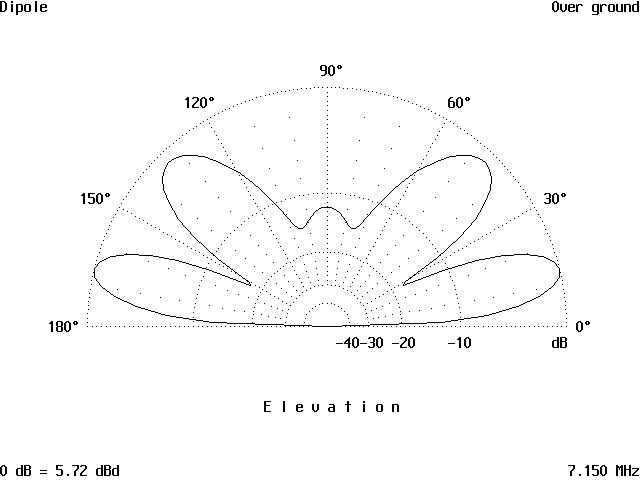
The vertical pattern in Figure 13 shows the large vertical lobe has almost vanished with only a small bump much reduced in strength, while two lobes have popped up at 45° and 165° and the major lobes have dropped to approximately 13° and 177° above the horizon. This indicates the antenna will start to hear the DX stations earlier as the band opens up. Then, as the conditions improve, there will be a drop off in signal strength before being picked up by the higher lobes.
In Figure 14, the 3D view show the two higher vertical lobes are almost a circle again with very small nulls off the end of the antenna. This again creates the ability to have almost circular signal transmission and reception at the higher angles. This will allow signals off the ends of the antenna to be received and stations worked when the conditions favor these angles.
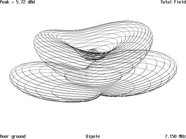
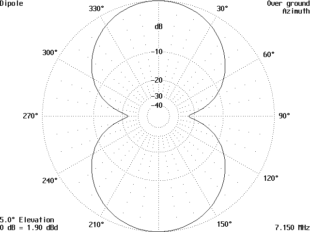
Figure 15 is the horizontal pattern of our dipole at the height of 1.25 wavelengths. The nulls off of the ends are so deep as to almost prohibit hearing any signal unless they are within several miles of the antenna’s location.
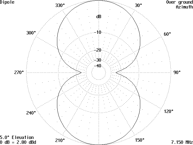
However, the 3D pattern in Figure 16, shows more than the 2D pattern, which is not shown. The two major lobes lowered to below 15° while the two lesser higher lobes also dropped somewhat and a large lobe sprang up directly overhead. The end results of this increase is the large lobe radiating to the vertical will give some improved local coverage, while the major lobes at the lower angles will improve DX slightly.

Going up to 1.5 wavelengths gives the horizontal pattern in Figure 17, very slightly increasing the nulls off the end of the antenna, but no other changes can be seen.
The vertical pattern in Figure 18 shows drastic changes again. The two lowest lobes are now at 10° or less above the horizon and the secondary ones are now at 30°.

The large vertical lobe present at the last level has now gotten a dimple. Figure 19 shows the 3D view of this pattern. It is an antenna with considerable radiation from 30° and less, with enough at a higher angle to give moderate coverage out to 1000 miles. But, there is a chance of some dead zones caused by short-range skip.

Now for strictly conceptual looks, because most of us will never get our 40 meter antennas anywhere near the lofty heights covered many reasons, mostly money, the next pattern is from the antenna at 9,600 ft. As you can see from Figure 20, the pattern is still the same, as far as the horizontal pattern is concerned. The nulls have sort of shifted outward some, but there is no great change.
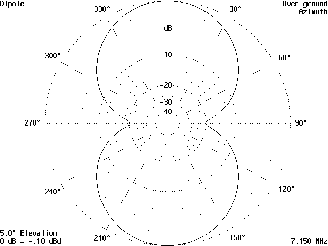
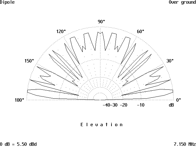
The real shocker is the vertical pattern in Figure 21. It looks like something spilled on the floor, with all sorts of jagged lobes everywhere. The two lower lobes are still below 10°, but how good this antenna is for DX is something we will never know.
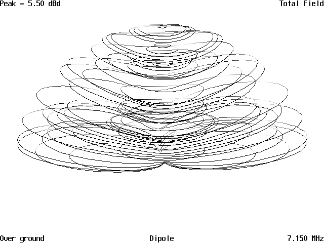
Looking at the 3D image in Figure 22 leaves the impression of confusion, as there are so many ragged lobes, none seem to dominate.
The reason for the patterns to change as the heights increase is because of increased reflection from the ground further out from the antenna as the height is increased. This in turn caused phase cancellation and addition to the signal from the antenna not reflected from the ground because it was radiated at an angle above the horizon. Finally, the 9,600-ft. antenna has so many reflections to cause it to not have any really powerful major lobes at any angle.
As far as high-frequency antennas on aircraft, that is beyond the scope of this article. Most of us can not afford that sort of luxury, so that is going to be left to the military and commercial airlines. The useful heights we can reach are most important. Keep in mind, the patterns are the same on reception for you short-wave listeners. If you are wondering about your antenna because it falls in between the heights used in these calculations, your antenna pattern will fall in between the patterns also. But, keep in mind the surrounding objects will determine what your antenna pattern looks like as well.
For those interested, these patterns were done using AO6.5, with a coastal high conductivity terrain for ground, and using a normal desktop PC computer running at 200+ MHz.
Originally posted on the AntennaX Online Magazine by Richard Morrow, K5CNF
Last Updated : 14th March 2024
