An Accidental Antenna Discovery


During the course of working on a high gain version of the ZL Special I happened to make a rather interesting discovery. I had done some work in the past with the W8JK Special, which is a close spaced phased array and knew that it could work on the higher bands other than for which it was designed for. So just for fun I decided to see how low I could get this antenna to work. I was rather amazed to find out that the antenna could be used on 80 meters and still exhibit some gain. It was also showing evidence of directivity and therefore could be rotated and signals could be peaked for maximum on receive and also increasing the transmitted signal in that direction. It is also bi-directional and this can be an advantage in some cases.
Now the antenna was modeled at a height of 54 feet (16.416 Meters), reflecting a tower or pole height of 50 feet (15.2m) and a mast height of 4 feet (1.21m). Boom length is 3 feet (0.912 m) and the element lengths are 16.5 feet (5.016 m) for the front element and 17.5 feet (5.32m) for the rear element which is fed out of phase 180 degrees from the front element Ground was characterized as high conductivity, coastal plains.
Above is a diagram of the antenna, showing all the dimensions of the components.
Figure 1 is the horizontal pattern of the antenna on 3.5 MHz and shows that the radiation pattern is an oval and the gain at 5 degrees Elevation is -10.55 dB. However, at 48 degrees the gain is 4.07dB.

Figure 2 is the vertical pattern and shows an increase in gain at the higher angles of radiation. The gain is 4.07 dB at 83 degrees. This could be called an NVIS antenna, a near vertical incidence antenna, but is still directional.

Figure 3 is a 3D view of the total radiation pattern and shows that the pattern resembles a bun of some sorts. It shows that at ground level the pattern is a figure 8 and as the height above ground increases, the pattern becomes more cylindrical as the elevation increases towards the vertical.

This pattern changes slowly as the frequency is increased an at 20 meters the bi-directional pattern begins to become more directional and Figure 4 shows the horizontal pattern of the antenna at 18.1 MHz.

Figure 5 shows that several minor vertical lobes have come into being at 18.1 MHz and that the gain has increased to 10.71 dB. This is not a disadvantage as this will allow you to hear stations that may be closer in that cannot be heard by the lower, higher gain lobe.

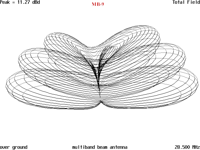
Figure 6shows the 3D pattern of the antenna and shows the general shape of the antenna radiation pattern. Figure 6 shows the 3D presentation of the pattern. The deep nearly vertical null can be seen, as can the secondary vertical lobes.

Moving to 10 meters, the antenna shows some slight gain towards the front of the antenna and that the beam width has decreased rather drastically. There are rather deep nulls to the side of the antenna but significant gain to the front and rear. Figure 7.

The vertical pattern is presented in Figure 8 and the secondary lobes in the vertical pattern can be seen. At 10 meters the gain has increased to 11.38dB and the angle of radiation has dropped to 9 deg. This makes this antenna a real good DX antenna.

Figure 9 is the 3D view of the pattern and shows the lower radiation angles of the smaller lobes that have come into being. The beam width is now 42 degrees and even though it is bi-directional, it still is a mean DX antenna. Being bi-directional is not a real disadvantage as it allows you monitor two paths 180 degrees apart, which could be used to advantage. It will allow you to monitor for DX stations behind your primary area of listening interest and that would allow you to nab a DX station the instant they transmit.

The following graphs show how the beamwidth narrows changes as the frequency increases and how the angle of radiation decreases as the frequency increases and lastly, how the gain increases with frequency.


Since this is a modeled antenna and has never been constructed, it looks like a good antenna for some experimenter to build. The biggest problem is that the impedance varies from extremely low on 80 meters to moderate at the highest frequency of operation. The antenna could be fed with ladderline or twinlead and a good tuner could be used to handle matching chores. It is an interesting project to pursue further.
Originally posted on the AntennaX Online Magazine by Richard Morrow, K5CNF
Last Updated : 30th April 2024
