Old CB Antennas Come Alive on Two
Are All Hams Bargain Hunters?
I think I am typical of many Hams that just can’t pass up a “Bargain” at the at the swap meet, garage sale or the local radio shop! Have you ever noticed, seemingly overnight, you have collected six mobile microphones at only one dollar apiece-who could pass up that deal? Even though you may not have any mobile gear, you tell yourself “That you have to start somewhere”. Or that HT you picked up at a give-away price, to be sure, has made a good paper weight since the swap meet two years ago!
Perhaps I’m a “Collectoholic” and my brother and sister amateur radio operators don’t have this problem, but I suspect many of us have a touch of it. If you like to “Home Brew” your projects, you are probably a bigger collector, such as myself. As I have drifted through the world of “Radio Junk”, as my wife refers to it, it seems I have collected a good number of old Citizens’ Band Radio antennas. Trunk mounts, roof mounts and several magnetic mount versions. My first reason for doing so was to tune them up on ten meters for my old GE Master II in the car or the HR-2600 in my Pickup. Well, the collection has grown to a good handful, at a cost of a dollar or two each. Two of them did get modified for ten meters and work reasonably well for local repeater work. They do not, however, outperform the full quarter wave whip installed on my truck.
Several years ago I purchased a Radio Shack 2-meter Mag-Mount 5/8 wavelength antenna to use with the then new car. It has performed very well in comparison to the1/4-wave that proceeded it. I have compared the two, side by side (so to speak), and the 5/8 wave has always outperformed its shorter brother as you might well expect. It is a bit more directional because of position and perhaps the lower radiation angle, which accounts for its improved gain. Since the base of a Radio Shack CB antenna and the two meter antenna looked almost identical, I couldn’t help but pull the loading coils out of both units to take a look.
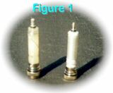
If you refer to Figure1 you will see the coil form and assembly is identical in both antennas, with the exception of the number of turns on the form, and that it is shunt-fed for matching not just a series loading coil as it is in the two-meter design. This is hard to tell from the photos however.
The coil modification to convert the “CB” antenna for two meter operation is a simple, after-supper job very suitable for a first time antenna project for those readers who may be new to “Home Brewing” antennas or anything else for that matter. If this describes you, fear not. This antenna conversion is an easy first time antenna project that will be well worth the effort put forth. You will not only gain a bit of technical knowledge in the process, but something much better that you can’t buy for any amount of money-that feeling you get, deep down, that says “I Built That Antenna Myself!”
Before You Start!
In addition to some basic hand tools, you will also need a soldering iron, solder and a reasonably good quality SWR meter. Don’t get caught in the trap of using a low cost, “CB” type meter. They barely work at 27 MHz let alone at 148 MHz! If you don’t own one, or you cannot borrow a unit from your club or a friend, then it may be a good time to consider making an investment in a good quality VSWR meter designed for the frequency range of interest to you-be that HF 2-meters, 222 MHz, 440 MHz or higher.
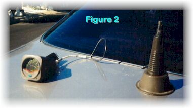
One of the best, most versatile meters on the market is the old Bird model-43 but, even used, they are costly. As a practical matter, from a cost-performance point of view, I have been using a DAIWA model CN-401M (See Figure 2) for several years now with good results at a cost of less than one hundred dollars. Its frequency range is between 3.5 MHz and 150 MHz and has two power ranges, 0 to 15 watts and 0 to 150 watts. In addition, it’s designed using a dual pointer meter (Crossed Needle) so that you do not have to switch between “Forward” and “Reflected” for each measurement! Both readings are given at the same time.
One more test equipment item you will need for most antenna work, and is relatively inexpensive, is a good quality dummy load. (The dummy load or Terminator I am discussing here is a 50-ohm unit most often used at VHF and UHF frequencies. 75-ohm units are also available.) Again, it must be rated in the frequency range and at the power level you want to work. I have had very good results at 2 meters with a Radio Shack 50-ohm dummy load, part number 21-506, rated at 15 watts, 500 MHz, for a cost of less than twenty dollars. There are some excellent values on the Surplus Market as well. Places such as Radio World in Boulder City, NV and Fair Radio Sales in Lima, OH are good examples. Working with antenna development and modifications, as in this case, a known impedance standard, 50 ohms at this point, will always provide you with a reference to come back to, to see how your antenna, cable, connectors, matching network, etc. are looking in comparison to that standard 50-ohm value. In addition, one seldom thought of need for a good dummy load is to determine if your SWR meter is telling you the truth or not.
To do a quick calibration on your SWR meter, simply run a short cable of the proper impedance directly out of your transmitter through the SWR meter with the meter being terminated by your dummy load at its antenna connection. You should be able to set your forward power to the reference mark and see little or no power in the reflected mode. To make sure the meter is not giving a false indication in the reflected position, repeat the same test once again with the dummy load and the output from the transmitter reversed at the meter. With this test, the forward and reflected positions on the switch, or the arrow direction if you use a Bird-43, will be reversed. However the forward power reading (now actually the reflected power due to reversing the input and output connections) should remain at or very close to zero. If this is the way your test results come out, your SWR meter is probably working reasonably well.
Modification Details
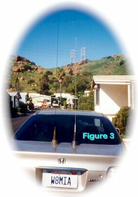
As mentioned earlier, this modification of a Radio Shack base loaded Citizens’ Band antenna to function as a 5/8THS wavelength 2-meter mobile antenna, is quite simple. It involves removing the plastic shell covering the coil by tapping the threaded stud sticking through the top of the shell, while holding the shell on a flat firm surface. Then unwinding the majority of the loading coil and replacing the CB whip with one of the proper length (49.5 inches (1.26m)). If you refer to Figure 3, you will notice the CB antenna, shown on the right side of the trunk lid, is shorter in length than the two meter, converted antenna, on the left. To complete my first conversion quickly, I purchased a new whip directly from Radio Shack Parts division4 (800-THE-SHACK) at a cost of $10. I have constructed several additional units using the top four-plus feet of an old six-meter whip. Another whip was purchased from Fair Radio Sales for about $6. Another was converted by having two scrap mobile CB antenna whips welded together, filed smooth and cut to the proper length. (This is not worth the effort, but it was fun!)
Referring back to Figure1, you will see the two meter antenna only has three and one half turns used to complete its coil. It is wound with the first three turns close-wound at the top of the form, with the last half turn going to the bottom solder connection. Be careful not to solder the unwound coil wire to the ground stud at the extreme bottom of the form. (Yes you’re right, I made that mistake, but only once!!) The CB coil has approximately 25 turns, close wound, the majority of which must be removed and a new solder connection made. Begin by unsoldering the end of the loading coil from the bottom of the coil form. A hot 40 to 50-watt iron is required to complete this task. Use care not to apply the heat any longer than necessary. The plastic form will melt quickly. Have a wet sponge ready to quench the heat after you remove the coil wire. Begin to unwind the coil wire until you come within four turns of the top. Leave about a six inch pig tail to work with, cut off the remaining unwound coil wire and discard it.
Unwind the remaining turn until you have a close-wound, three-turn coil at the top. (Note: The newer versions of this antenna have groves molded into the plastic coil form making this job that much easier. If you have this type of form, keep the coil wire in the groves for three turns.) Now tightly wind the last half turn from the top to the solder post near the bottom as previously mentioned. Strip any enamel coating that may cover the wire and wind the wire around the lower post and solder. Once again, be careful not to use excessive heat, but be sure you have a solid connection.
You may wish to place a drop or two of fast drying epoxy at the bottom of the third turn of the coil, let it harden to prevent movement, and then continue with the bottom solder joint. Be sure all solder joints are solid and shiny. Remove any flux or other residue. Mobile antennas take a good deal of physical abuse and must be solid. Insert the coil back into the plastic cover. You can use the original CB antenna spring, or a nut and a flat washer, to draw the coil back into the shell. I always coat the base of the coil and the “O” ring seal, as well as the top threads, with an electrical grade of silicone grease which is available at most automotive parts stores, or at your local electrical supply house. While you are at the electrical supply house, a small tube of silicone grease for use on aluminum wire is great to have around for any antenna project that uses aluminum tubing or pipe. It will help parts slip together easier and you will be very happy three or four years from now when you have to pull your “Super Band Slammer” down to replace it with the new, improved “All Band Slammer-2” that you may read about right here, on-line, in antenneX! The silicone grease will also help keep the moisture and road grit out of the coil assembly on this mobile antenna project.
Assembling The Modified Antenna
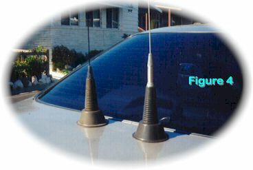
You have a few choices in how you wish to assemble your finished two meter antenna. Making the assumption that you started out with a Radio Shack brand CB antenna, similar in appearance to the one shown in Figure 4, or any of the other popular brands, such as Antenna Specialists or Ameco, as an example. Most will usually convert in a similar manner. Your first option will be to decide if you wish to use the spring that comes with the CB antenna or not. The magnetic Mount, two-meter antenna manufactured by Radio Shack (See Figure 4) does not come with a spring.
You will find the whip is so flexible that one is not needed in all but the most rugged service. Please remember, you must shorten the whip length by the length of the spring, if you elect to use it. If you choose not to use the original spring, then you must fabricate a mount to hold the loading coil into the plastic shell and hold the whip of your choice tightly together. Optionally, you can purchase the whip adapter nut4 for about six dollars from Radio Shack. I have constructed this modified antenna both ways, on several occasions, and prefer the use of the spring. I save six dollars (US) as well! Admittedly, it is usually easier to purchase the adapter nut and be done with it. That choice is yours to make.
The next choice to make is how you wish to mount your new two meter “Thunder Rod”! If your recycled CB antenna was a magnetic mount to begin with, you will have one additional option of using it as a “Mag-Mount” version which will function quite well in the two-meter frequency range. They do not, however, work well at 27 megahertz. Therefore, you should be able to locate many slightly used units that have been discarded by discouraged CB’ers! You can also roof or trunk-mount this antenna, if you so desire. If you have found a mag-mount unit, but wish to trunk-mount it with a small bracket-or roof-mount the antenna-it is very simple to disassemble the mag-mount and use the hardware from that assembly to complete this task. To roof-mount the unit, using the mag-mount hardware, will require a 5/8THS inch (1.588cm) diameter hole. I have a magnetic mount in use on the family car, as shown in the photos, and a fixed mounted version in the center of the roof on my pickup truck. Both work very well and show a very flat VSWR over about a 2.5 MHz bandwidth.
Installation and Test
If you have selected the mag-mount version of this antenna, your installation is almost complete. Simply select a good location on your vehicle and set it down. Be certain to wipe any road dust or dirt from the mounting area first. In addition to preventing any paint damage, you want the greatest possible coupling between the magnet and the car frame. The top, center of the roof would be the best location from an RF point of view, a point of view which I assume your spouse may not share with you! A more practical location is usually on the trunk deck as shown in Figure 4 above. This will also allow you to run the coax feed line past the rubber grommet around the trunk lid, making a good seal without damaging the cable. In addition, if you live in or are traveling to a high crime area, or park at the airport for a week or so, you can easily place the mag-mount version into the trunk until you return. It only takes about 30 seconds to complete this task and it will also draw less attention to your vehicle without the antenna showing.
If you have decided to mount2 your antenna to the vehicle, either through a mounting hole drilled into the body or through the use of a trunk lid mount that may have come with the original CB antenna, be sure the ground to the antenna and cable braid is solid. Once again, if you suspect the cable or the connector has seen better days, replace them both! Route the cable to your radio location in a direct manner as practical. Be sure to leave a short but sufficient service loop on each end of the cable-at the antenna end, for moving the cable when the trunk is full, and at the transceiver end to allow you to remove and replace the radio at will. Most two-meter transceivers use UHF type connectors (PL-259 plug and an SO-239 chassis connector). Be certain the connector on your cable is well-soldered and assembled. Although I have suggested leaving adequate service loops on both ends of the cable run, do not use any more cable than necessary. RG-58 coax is quite lossy at these frequencies.
Install your SWR meter in the transmission line and key up, in low power, if it will give you a full scale reading on your meter. Now check your SWR. If it is extremely high, shut down and search for loose connections, shorted cable, open connections, and loose whip in its mount. If all this fails to produce any fault, it may be time to pop the coil out of the plastic shell and look for a problem. After having constructed many of these conversions, there was only one major problem that ever stopped me for any long period of time. The internal shorting wire connecting each end of the spring together had broken and the rusted spring was then acting as an intermittent loading coil. To adjust the whip length, loosen the set screw on the antenna spring and raise or lower the whip into or out of the spring, tighten the set screw and check your SWR reading again. If you can get the SWR down to 1.5 to 1 or better, lock down the set screw-you are ready to talk. I most always tune up on 146.52 MHz, the National 2-Meter Simplex frequency. I do so because I feel I will need the strongest signal when working or calling other stations on Simplex. Your ideal frequency is your choice for your own reasons.
In Summary
Other models, not shown here, may require a bit of coil tuning and whip pruning to have them work properly. I have used several different brands and all have come close to what has been shown here. Please remember, the important fact is to keep your whip length very close to the length stated. It is the lower angle of radiation that provides a compression effect in azimuth that will, in turn, provide a 3 dB gain or more. The 5/8THS wavelength radiator will provide this low radiation angle. The loading coil will provide the proper match to your transmitter. Adjusting your whip length between .5 and 1 inch (1.27cm – 2.54cm) would be well within normal tuning limits with an SWR in the range of 1.5 to 1 or less. If you get this close you’ll be in good shape. If your frequency use is closer to the top of the band, then you may have to shorten the whip by about one inch (2.54cm) 3. If you elect to purchase the Radio Shack replacement whip, you will not have to cut it at all unless you are using an additional spring. You will then have to shorten it by the length of the spring as mentioned earlier. I have also scaled down this antenna for use on 223 MHz by removing one turn from the coil and shorting the original CB antenna whip proportionately.
As with any antenna project, be certain the coaxial cable that came with the antenna is in good condition, not frayed, pinched or striped from being rolled up in the car window many times by its previous owner. Also check the solder connections at the antenna mount end as well as the connector. If in doubt, replace the cable and the connector. It could be three dollars well spent!
A Final Thought
Allow me to leave you with one additional idea. I, unfortunately, live in an antenna-restricted area. For some period of time I would, over the weekend, place a Mag-Mount version of this antenna on my sunroof, which is of steel construction, with excellent results. Then, I began to leave it on the roof all week long and not a word was said. Bravely forging ahead, I mounted another unit on the sunroof through a 5/8THS inch (1.588cm) diameter hole with the lead-in coming directly down to my radio room. The results have been very good for over a year to this point. I have also added an “L” bracket to yet another, for a fellow ham, with four 20-inch (.508m) radials made from 1/8″ (.318cm) brazing rod sloping down at approximately 45 degrees. He has it mounted at thirty feet (9.144m) on three lengths of TV antenna mast and gets excellent performance using it as a fixed station antenna. The gain it provides can make a big difference. In the price range from five to fifteen dollars (US), depending on your junk box and your options, it fills that deep inner need for every Ham, “To Find A Real Bargain”!
Notes
- I am working on a short future article that will go into more detail on the workings of your SWR meter and demonstrate some simple, inexpensive, test equipment to calibrate your meter with reasonable accuracy.
- Please refer to the ARRL Antenna Handbook for additional ideas on mobile mounts.
- Stainless steel, that whip antennas are made from, is very hard. It cannot be cut with a hacksaw or with normal wire cutters. If you must shorten the whip in this project. and have a grind stone, it will be an easy task to grind through the stainless rod. An alternate method, I often use, is to use the sharp edge of a small three-sided file. File about half way through the stainless rod and then “snap off” the piece you wish to remove.
Originally posted on the AntennaX Online Magazine by August Noecker, W8MIA
Last Updated : 25th April 2024