The Flat Top Antenna
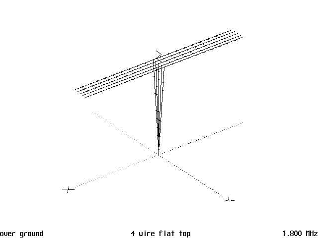

So an investigation of the old flat top was in order. Keep in mind that the wavelengths in use were as long as 20,000 meters, so a very large antenna was needed to radiate a good signal. Most of the time people operated where they could get out well, which is wherever their antenna resonated.
No one then knew anything about resonating the antennas to specific frequencies by cutting the antennas to correct lengths for the frequency desired. No VSWR bridges were available then either. Since that is no longer the case, a 5 wire flat top was modeled on the computer for all of the current amateur bands. This was done to satisfy a curiosity as to how well these antennas would do today on our current amateur bands. So one was scaled down to a more useable size and then modeled on all 9 bands in the 1.8-30 MHz range.
Figure 1 shows the basic configuration of a center fed 5 wire flat top, less supporting structures. The wires are spaced 1.5 feet and are made of #12. The antenna is 66 feet (18.24 meters) long and is 33 feet (9.12 meters) high and fed with a fan of 5 #12 wires. Some sort of antenna tuner is required as the impedance will vary very drastically over the range from 1.8 MHz to 30 MHz. if you desire to put up one of these antennas.

Figure 2 is the horizontal plot of the antenna on 160 meters and it is a perfect circle.

Figure 3 is the vertical plot which shows a fairly low angle of radiation, 30° or less. This indicates that on 160 meters the antenna could be a very good DX antenna which is hard to find due to the extremely large size of most 160 meter antennas.
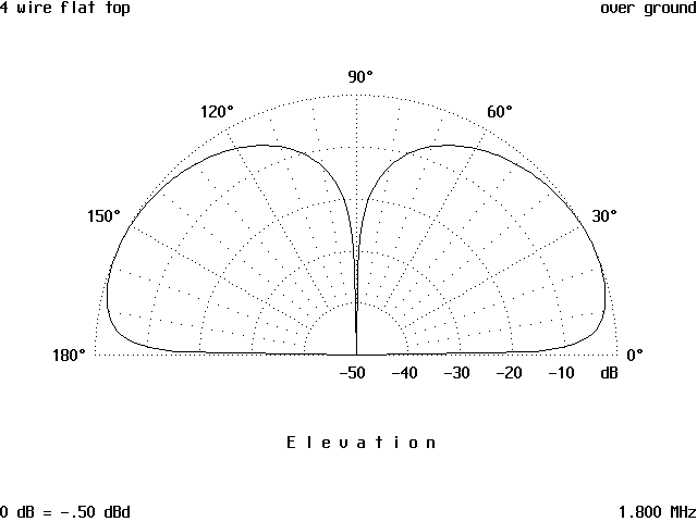
For 75, 40 and 30 meters, both the horizontal and vertical patterns are pretty much the same with low angles of radiation on these bands. This is useful again for DX, yet there is enough higher angle radiation to enable the antenna to work for local contacts as well. Figure 4 show the vertical pattern on 30 meters and it is a little higher than on the other three bands.
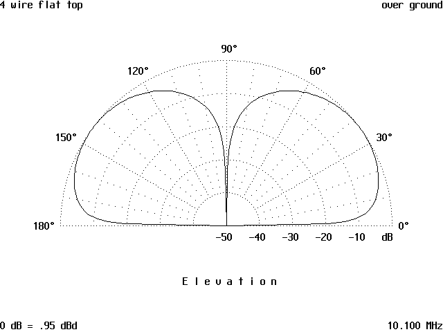
Figure 5 shows the horizontal pattern on 20 meters and it has become a rounded square.

Figure 6 is the vertical pattern and even though it has a major lobe at 10°, there is not much gain and a rotatable dipole at the same height would do better. The pattern on 17 meters is much better and for all practical purposes will be a rounded square.
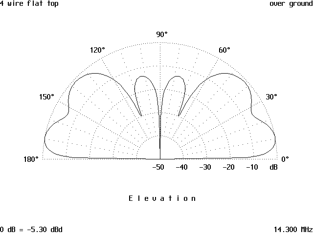
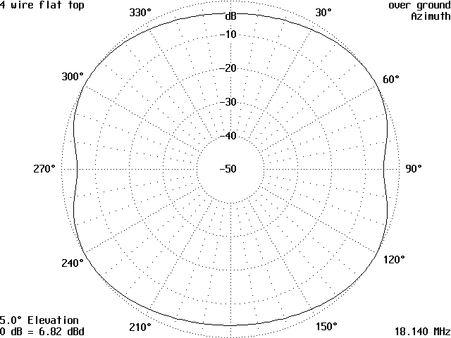
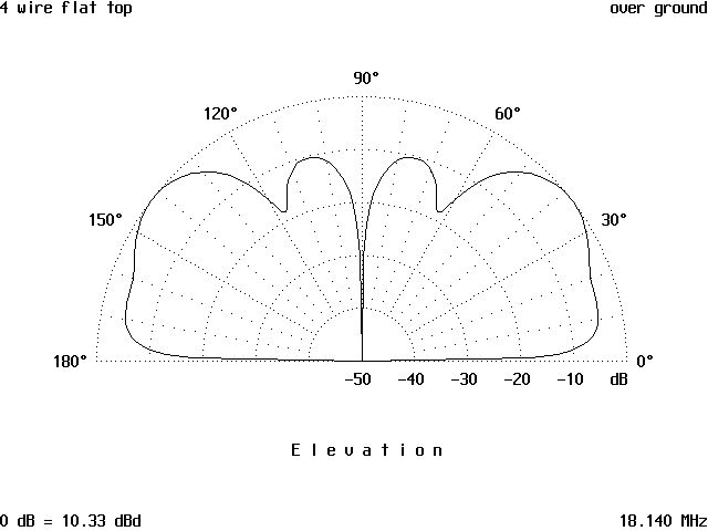
Figure 7 is the horizontal pattern and shows a gain of 6.82 dBd while Figure 8, the vertical pattern, indicates that a fairly good amount of the radiation takes place at around 35-40 degrees. There is still a lot of signal below 35 degrees and lower that will enable a fairly good signal to be radiated for DX work.
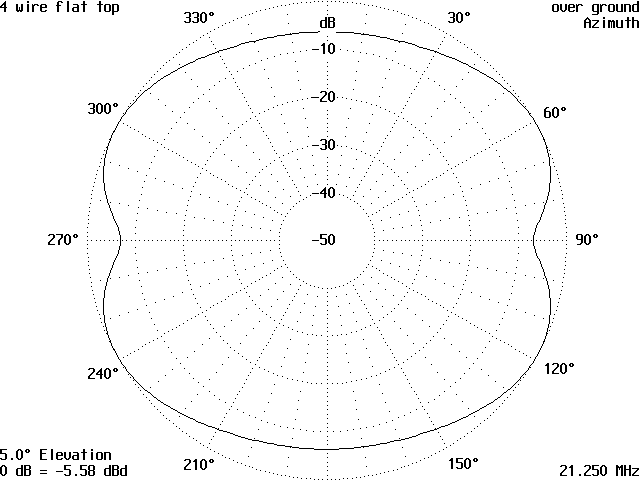
Moving to 15 meters, the horizontal pattern in Figure 9 show a decreasing signal with a -5.58 dBd level being shown on the outer ring of the pattern. The vertical pattern which is not shown, was almost identical to the 17 meter one in general shape, but with much less gain indicating that the antenna performance is falling off with an increase in frequency.
Moving to 12 meters indicates that this is becoming more the case as the horizontal pattern in Figure 10 shows a decrease in signal strength and the vertical pattern in Figure 11 shows that on this band the radiation is nearly vertical and therefore useless. There is radiation below the maximum at 65 degrees, but little gain. The conclusion is that this antenna will not do well at all on 12 meters.
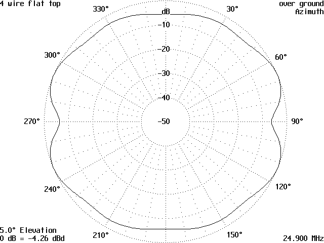
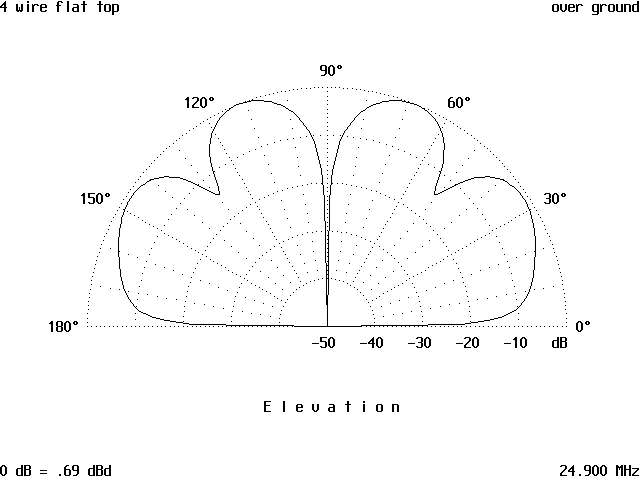
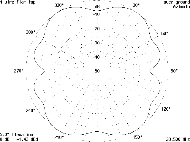
On 10 meters, the antenna again shows very little gain at the lower elevation levels and the horizontal pattern, Figure 12, has some dimples in it.
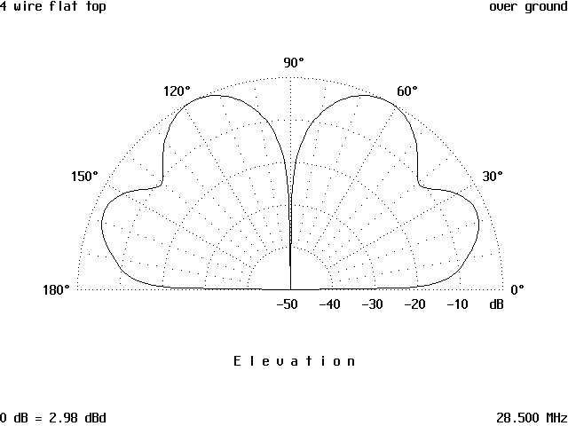
The vertical pattern in Figure 13 indicates any gain from this antenna comes at very high angles and therefore is useless for any sort of DX work.
The conclusion to be drawn from this case is that the flat top works well on the 160, 75, 40 and 30 meter bands and fairly well on 20 and 17 meters, but not well at all on the higher frequencies. This antenna and others bear further exploration for use on the lower frequencies where getting a good antenna is difficult, if not nearly impossible on the size of the city lots that most of us have to deal with. There will be more investigation of the older antennas no longer in use to see if there is a place where they just might work well for someone needing such a solution.
Originally posted on the AntennaX Online Magazine by Richard Morrow, K5CNF
Last Updated : 15th March 2024
