40 Meter Wire Beam
Getting a gain antenna for any of the low frequency bands is a problem due to their size. Phased verticals are one way, but many people do not want to use verticals for one reason or another. The alternative is to use a wire beam. Granted, the beam cannot be rotated, but by using a bi-directional beam, this problem can be alleviated somewhat.
So now the next thing is to find a beam that fits this criteria. The W8JK array is one. It has good directivity and is bi-directional. It is based on two close-spaced elements that are less than 1/4 wave apart, usually .125 wavelength. This is not a new beam, and it has been around for many years. Usually found on the higher bands, the array has a very low angle of radiation. It can also be used on higher frequency bands. Thus, one made for 40 meters can be used on 20 and possibly 15 meters and 10 meters as well.
The first JK array to be considered is the inverted V JK array. The centre of this antenna is 35 ft. high with its ends 20 ft. high and the spacing is 16.25 ft. Figure B-1 is of the vertical radiation pattern and it shows the angle of radiation is at 45 degrees, with a gain of 5.36 dBd. This is a decent amount of gain for a low antenna. Figure B-2 shows the horizontal pattern with a beam width of 60-65 degrees. Figure B-3 shows the antenna displayed with the current phase and magnitude displayed. You can see the antenna currents are approximately 180 out of phase. There is a slight difference due to the physical spacing being less than 180 degrees. Figure B-4 is the 3-D pattern and shows the deep nulls at right angles. This view is from about 45 degrees high looking down at the antenna at right angles from the elements.
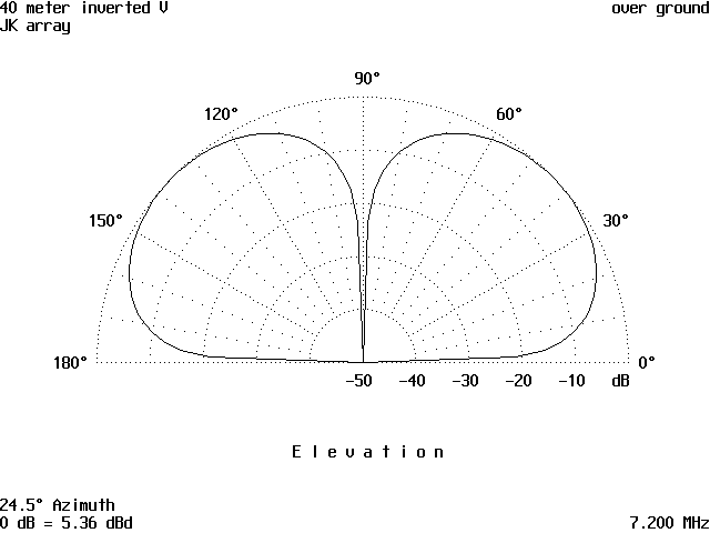
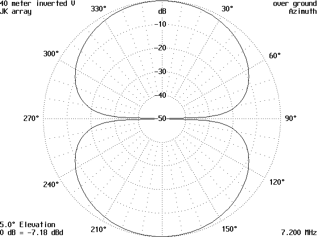
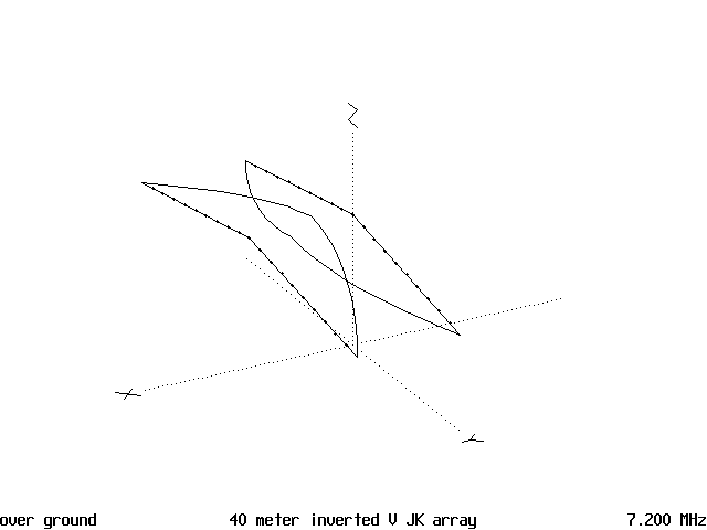
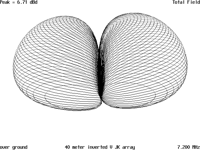
Figure 5 is the antenna without current distribution being displayed. You can see the interconnecting feedline. This feedline is usually 300-ohm twin lead and the feed point is in the middle and one end is twisted 180 degrees and connected to the elements. This gives the 180-degree phase shift between the elements which is required for proper operation. In case you are considering feeding the antenna at one of the elements and letting the twisted feedline take care of feeding the other end, don’t. The antenna will not work correctly if you do this.
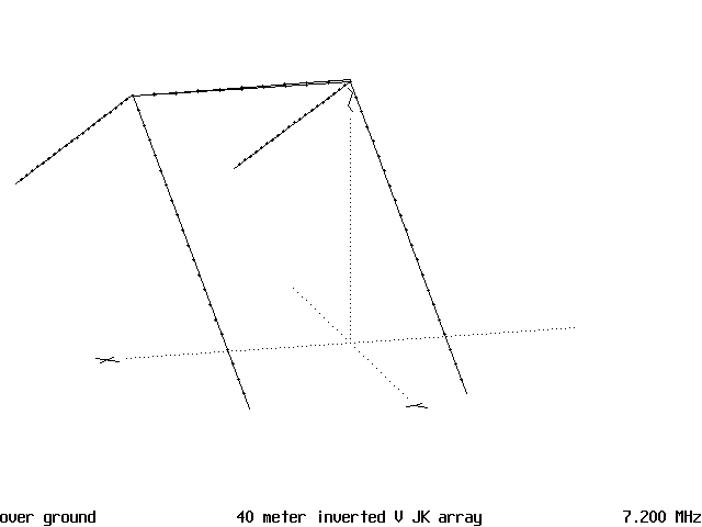
The only other item to consider is the antenna impedance is quiet low, less than 20 ohms in most cases, and must be matched before you can get on the air successfully. If you use 300-ohm twin lead and a good antenna coupler, this will not be a problem. Also, if you can make the feedline an electrical 1/2 wavelength long, matching the antenna will be easier. An electrical 1/2 length of feedline will reflect whatever impedance is connected at one end to the other end. So, if you have 16 ohms at one end, you will measure 16 ohms plus the resistance of the length of the feedline at the other end.
However, a quarter wavelength has the opposite condition, as the 1/4 wavelength transmission line will reverse what it sees at the other end. This is useful in impedance matching because, in other words, a 1/4 wavelength line that is shorted at one end will show an infinite resistance at the other end, or an open circuit. So, if you use a 1/4 wave long piece of coax connected to a high impedance antenna, there will be a change of impedance at the other end. Therefore, it acts like an impedance transformer. In this case, you must use a balun first to convert the antenna from balanced to unbalanced line. Then use a 1/4 wavelength transformer made of 72-ohm line from the balun to transform the low antenna impedance up to where the 50-ohm coax and transmitter are happy with it.
Here is one method to match the antenna. I have known several hams who have made these antennas and used this method to match the antenna which allowed them to get on the air. The twin lead is the easiest and those fortunate to own one of the old Johnson Matchboxes will have it made because this old antenna tuner could match nearly everything that could be connected to it.
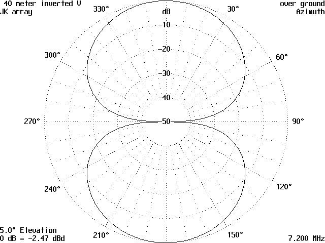
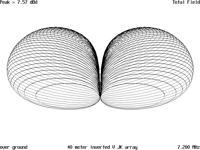
Now, if you can raise the antenna to a 1/2 wave height, you will be even better off. In Figure 6, which is the pattern of an JK array raised to a height of 65 ft. and the antenna configured with all of the element ends also raised to 65 ft., it can be seen that the horizontal pattern has narrowed very slightly. Figure 7 is the vertical radiation pattern, and this shows the vertical radiation has dropped to 26 degrees and the gain has gone up 7.57 dBd. This is a definite improvement and is worth doing if you can. Figure 8 is the 3-D pattern and shows the deep nulls at right angles to the antenna just like the lower antenna.
By using these non-rotatable antennas and picking the directions you would like to work, it can increase your chances of making the elusive DX contacts when they are there. In my case, I would be able to point the antenna toward Europe, the South Pacific, New Zealand, and Australia. The alternative directions are due East and West or, if I chopped down two trees, Northwest and Southeast. Tree chopping is out, so I would stick to the Europe/South Pacific directions.
Using wire beams of this nature are well within the capabilities of most hams and will work well if assembled and put up correctly. Not being able to afford a big tower and 40-meter beam does not mean you cannot work DX with a low powered rig. Just put up a wire beam.
TABLE OF DIMENSIONS
- Element lengths 65.45 ft, for 7.150 MHz.
- Element spacing 16.25 ft
If you build one of these antennas, they will load up on 75, 20, and 15 with good gain. The higher antenna works very well on the higher bands, but both suffer from multi-lobing on 15 which means there are several large lobes on either side of the major lobe. These are down several dB from the major lobe. Because of this, only 20 and 75/80 meters should be used.
Originally posted on the AntennaX Online Magazine by Richard Morrow, K5CNF
Last Updated : 25th February 2024
