All-Band Long Wire Antenna
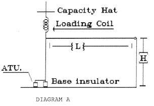
This is a rather unusual antenna in that it combines elements of several different antennas, namely, the long wire and the top-loaded vertical. In Figure 1, you can see there is a vertical and a long wire, tied together. The vertical is top-loaded with a capacity hat. Just below the loading coil is where the long wire ties to the vertical mast. There is a base-mounted antenna coupler, (ATU, short for “antenna tuning unit”) which resonates the antenna on the frequencies of interest. The height of the antenna, {H} is going to depend on how much you can get, but generally, 30 or 40 feet will be plenty. The length, {L} will also depend on what you have available.

The loading coil can be anything that will resonate your antenna on whichever frequency you want the vertical to resonate. The antenna has been used with an old Shakespeare 2 MHz marine antenna to bring 160 meters into the range of the antenna, but what you want it to resonate on is going to determine the coil size and inductance value. The same thing can be said for the capacity hat if you need one.
The long wire length should be set also for the lowest frequency you are going to operate on, a total of a quarter wavelength counting the length of the vertical section, even if you set up the vertical part of the antenna for 160. That way you will get a mixture of horizontal and vertical polarization on 160.
This antenna could be set up to operate 160/15 meters or any other combination of frequencies by altering the dimensions of both the horizontal and the vertical elements. Any coil is used for the top loading coil is going to act as an RF choke, and the vertical part below the coil and the horizontal section will be the parts of the antenna that will do most of the radiating. The top-loading section will not resonate on the higher frequencies, and therefore, will radiate very little. Of course, the longer the horizontal part of the antenna, the more directional it will be along the length of the antenna on the higher frequencies.
The impedance variations at the feed point will be very large, and the coupler will have to match every variation that occurs with each frequency excursion. An L network will do a good job, as long as it can be made reversible to handle the lower feed point impedances to be found at the lower frequencies. Just be sure the components selected can stand the power your rig puts out.
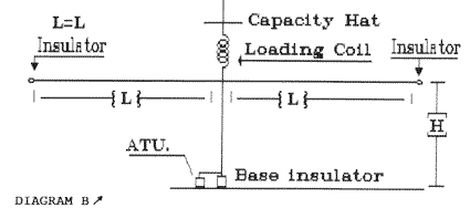
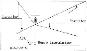
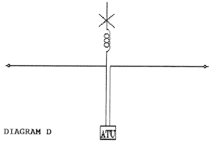
There are variations and Figure 2 and Figure 3 and Figure 4 are illustrations of what could be done with this antenna with the application of a little imagination. In Diagram B, the addition of another equal length horizontal element makes the antenna into a center-fed T.

Figure 3 shows the addition of shorter elements that add up to a total of 1 /4 wave length from the ATU to the end of that particular wire.

Figure 4 shows a twinlead-fed dipole with the top-loaded vertical tied to one side of the feed line.

By tying the twinlead together, the antenna should load up on the low band vertical section, but how would it load up on the low band vertical section if the twinlead was not tied together? An interesting question and one that bears investigation. If a person has enough room, the usage of several different lengths of horizontal wire will improve the performance of the antenna on any particular band, not to mention the characteristic impedance on the low band improvement. No matter, this antenna is one that has a lot of potential, if someone wants to take the time to work with it.
Originally posted on the AntennaX Online Magazine by Richard Morrow, K5CNF
Last Updated : 17th March 2024

