Home Brew Collinear
Of course, I considered the family of quarter-wave ground planes and some of the coaxial designs that many of the commercial producers are doing so well. I also considered the half-wave antennas, including the “J”. However, I like to keep things simple, and did not need to get overly complicated, so I finally decided on a variation of the 5/8 wave radiator.
My reasons for choosing the 5/8 wave radiator included its apparent relatively high gain. As a vertical radiator, the 5/8 wavelength antenna tends to compress its radiation toward the horizon, which is where you want it when you are working 2M. By comparison, a 1/4 wavelength vertical radiator squirts too much RF energy at a high angle – not too useful unless you are trying to work aeronautical mobile stations.
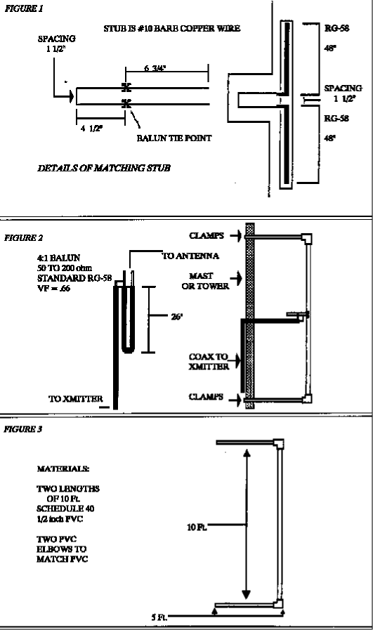
As long as I had decided on a 5/8 wave radiator, I asked myself what could be better than that? Why, it was two of them, naturally. And this type of radiator, it turned out, was not a complete stranger to me. In a horizontally polarized form, I had successfully used it in the 1960’s as the driven elements in the W6GD “Extended-Expanded Collinear” array. In a nutshell, the use of two 5/8 wavelength radiators, fed much like a standard dipole, really concentrates the pattern, and just where you want it, right on the far horizon. (See Figure 1)
The next consideration was physical, not theoretical. How to support it? Since it would be an outrigger array, set out from my tower (or mast), I wanted it well supported, and XYL- approved (i.e., not too ugly). The solution came in the form of two 10-foot sticks of 1/2″ PVC (schedule 40). One stick contains the vertical radiator; the other (cut in half) supports the first stick. This PVC is inexpensive, can be glued to itself, can be clamped to the mast (or tower), has a nice white appearance, is virtually transparent to RF at 146 MHz, and is weatherproof. What more could you ask for? After this, the antenna almost put itself together. (See Figure 2).
The performance of this antenna at 35 feet has been highly satisfactory, and represents the most dB gain per dollar I’ve ever enjoyed.
Construction Notes
The actual radiators in the one I built were chunks of RG-58 cut to 48″. Holes just large enough to permit cramming the coax into the long stick of PVC were drilled at an angle near the center of that stick. PVC “elbow” connectors are glued at top and bottom of the long stick, as are the two 5-foot short sticks (in the same plane, please, so they both contact the same tower!). Seal with RTV (white silicon bathtub sealer) to weatherproof the whole thing.
Ah, yes! One more little thing. How do you feed this bird? The feed impedance between the bases of two 5/8 wave radiators is NOT 50 ohms! A matching transformer is required, as well as a means of changing from an unbalanced feedline (coax) to a balanced (symmetrical) load. The solution I used (and it’s not the onlyone) was to use a 4:1 coax balun. In standard RG-58 the balun is 26″ long. This takes the 50 ohms unbalanced feed and transforms it to 200 ohms balanced. This does not take us as far as we need to go, since the feedpoint of the “2 X 5/8” is still higher than 200 ohms; but it’s a good start in the right direction (See Figure 3).
To complete the process we need a matching stub of open wire (#10AWG) line at the antenna’s feedpoint to which we’ll connect the 200 ohm end of the 4:1 balun. This is the only part of the array that is less than squeaky-neat. This matching arrangement hangs out in the open air between the center of the long stick and the supporting mast (or tower). (See Fig 4) Fortunately, it isn’t large, and doesn’t show up well from below. Well, you can’t have everything, at least for less than $15.

Originally posted on the AntennaX Online Magazine by Bill Nogues, W5GVE
Last Updated : 9th March 2024

