Build a Desktop Gain Antenna for 2 Meters
Thanks to modern construction practices, when I am in my office with my hand held two meter transceiver, I can barely get into the local repeater, located less than five miles away. When at work, I normally have better things to do than chat on the machine, however on those occasions when I work late on net night, I like to have the capability to have my say if I want. Additionally, being active in RACES operations, the ability to communicate through the repeater during drills is important to me. During an actual emergency, it would be even more so.
Deciding on a gain type antenna to be used indoors, to enhance my radiated signal, was simple. I decided against purchasing a more powerful h/t and my boss decided against an outside antenna. By the same token, whatever antenna I used inside had to be as unobtrusive as possible, not be an eyesore, nor get in the way. A telescoping whip antenna came to mind, but I didn’t want to be bothered with radials, which ruled out a quarter wave. By lengthening the whip to a half wavelength, I eliminated the radials, but a direct connection to the radio was impossible, due to an extremely high impedance. The solution, then, would be to make the antenna system match the radio by an impedance transformation scheme.
Some time ago, I was doing a post mortem on a broken marine vhf antenna and was astounded to find that the expensive antenna had nothing inside it but a wire radiating element, a short length of coax with the shield connected only at the feed line end, and a shorted stub. For almost $50, I had purchased a quarter’s worth of coax and a nickel’s worth of wire. The PL-259 on the end of the cable had cost the manufacturer more than the antenna itself; here was a case of the container being more valuable than the product inside! Well, you live and learn.
That antenna piqued my curiosity. I knew that a simple quarter wave antenna operating in conjunction with a ground plane has an impedance of approximately 38 ohms. I also knew that a vertical antenna a half-wave long, such as in the marine version I examined, could have an impedance of several thousand ohms. However, in some circumstances, and the marine antenna was one of them, a half wave antenna does not require a ground plane. What I needed to know was how to configure a similar antenna for two meters, and what I was going to do with it when I finished.
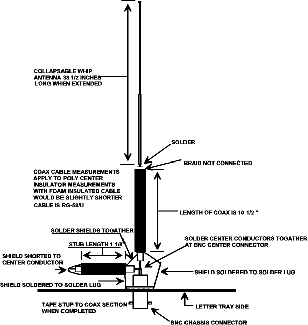
In doing a little research, I stumbled across exactly the information I needed. It seems that the combination of the short section of coax and the shorted stub existed to transform the high impedance of the vertical element to that of the 50 line. Had the antenna I was trying to match had an impedance lower than 50, the stub would not have been shorted.
I wish that I could say that I bread boarded a half wave whip and appropriate connectors in the configuration that I was going to use, conducted an accurate SWR check, plugged the resulting value into a rather complicated formula, and calculated the length of the coax matching section and the stub mathematically. I wish I could, but I can’t. What I did was measure the parts of the marine antenna and go from there. As the Marine VHF band lies quite near the 2 meter Ham band, I figured that the lengths would be fairly close.
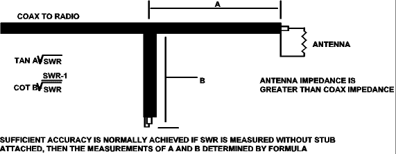
As the stub wasn’t very long anyway, I added an eighth of an inch as a starting point. Arbitrarily selecting thirteen inches of coax, I began snipping off 1/4″ pieces of the braid and outer jacket at a time, adjusting the length of the whip antenna for minimum SWR. When I arrived at a point where the SWR was imperceptible near the frequencies I was most interested in, I cut off the exposed piece of center conductor and insulator, soldered the remainder to the antenna, and lengthened the whip by the same amount. I found I didn’t have to bother the stub length. That’s how I did it, although I have included the formulas for anyone who would rather do it the hard way Figure 3.
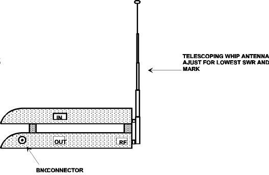
Having a quite serviceable antenna Figure 1, I now needed something to put it in. Simply because I had one anyway, I assembled the antenna unit in a plastic desktop letter tray Figure 2.


Perhaps it seems rather silly. After all, a gain type letter tray is about the last thing anyone really needs, but it does meet my criteria: It is barely noticeable (when the antenna is collapsed), it is unobtrusive, and it provides an awful lot of gain, compared with a standard “rubber duck” antenna. The fact of the matter is that the “duck” is about 6 dB weaker than the half wave.
I am very satisfied with this indoor, compromise antenna. I no longer have any difficulty getting into the machine and it works quite well for local simplex operations, too. The small amount of expense was certainly worthwhile, and I learned something from this project as well.
References
- The ARRL Antenna Book, 14th Edition
- 73, March 1988, p. 78
Originally posted on the AntennaX Online Magazine by Arliss N. Thompson, W7XU
Last Updated : 6th March 2024
