An Antenna Study - Part 1
There are numerous questions about antennas that are best answered with pictures (radiation patterns). For the next several months, there will be a short section under the above title, and each part will provide information relative to antennas. This is based on a computer study done to answer the most frequently asked questions. There is adequate information already developed for six months. If you have particular questions that are best answered by computer analysis please send them in and we will try to answer them for everyone’s benefit.
This series is based on the MININEC3 program. This program will provide the characteristics of virtually any wire antenna configuration including multi-element beams. The program has one major deficiency (limitation), it is not capable of providing accurate antenna impedance characteristics as a function of various types of grounds. It does produce accurate radiation patterns for any type of ground. The other limitation is the characteristics of a fanned wire dipole, since it is not able to determine current flows accurately in parallel wires having the same currents. Otherwise, it is an excellent program.
Since this is a series of articles, the figures will be numbered consecutively throughout the series, rather than starting with number 1 for each month. The effects of ground are very important, both the characteristics of ground and the location of the antenna relative to ground. For this study average ground with a dielectric constant of 12 and conductivity of 0.002 MHOS/meter was used. A few runs are included over fresh water with a dielectric constant of 85 and a conductivity of 0.02 MHOS/meter.
This month we will begin the series with an investigation of the effect of the number and length of radials on a vertical. As stated above, we are presenting the effect on the radiation pattern. There is an additional effect due to efficiency. The true pattern shapes must be reduced by the efficiency factor. As a general comment, 4 good radials will allow about 50% efficiency (-3 dB), and 120 are required to achieve high efficiency.
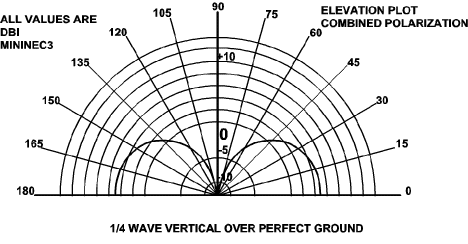
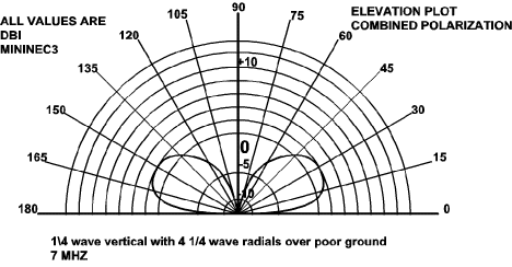
Figure 1 is the computer plot of a 1/4 wavelength vertical over perfect ground (for reference). Since the effect of imperfect ground varies as a function of frequency, the frequency will be noted on each figure. Figure 2 emphatically shows the effect of poor ground. Note that the gain dropped from 5 to about -2 dBi at an elevation angle of 10 degrees, or a loss of 7 dB at the optimum DX angle of radiation, over poor ground compared to perfect ground.


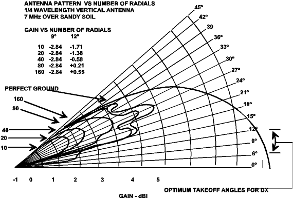
Figure 3 presents the effect of the number of radials on a vertical antenna. The curves are drawn from computer generated data to allow the display of several sets of data on a single plot, which provides the convenience of immediate comparison.

Figure 4 presents the effect of the length of radials on the antenna pattern. Now you know why you need 1/4 wavelength radials (or longer) and lots of them (at least 20). The radials do not need to be resonant. The RF currents do not penetrate the ground to any significant depth. Therefore, the radials should not be buried. If they are laid on the ground and covered with grass, they will have the maximum effect.
More to Come…
Originally posted on the AntennaX Online Magazine by Ted Hart, W5QJR
Last Updated : 5th April 2024

