Super Long-wire Antenna
Several weeks ago, I was listening on 75 meters and happened to overhear two hams up in the northern reaches of Montana talking about another ham they knew who had a really long wire antenna. Seems there was one of the EHV (Extra High Voltage) power lines running across part of his ranch and the Power Company had decided to abandon the line after many years, due to the extreme difficulty of servicing the lines during the winter. It was also going to be very difficult to dismantle the lines, so they had rather abandon them as well. Thus, the Power Company asked the permission of the owner to just leave the structures and strung wire. A bright idea struck the ham! In exchange, the ham landowner asked them to bring down connections from the 3 large conductors to a point where he could hook up a feedline to the power lines. Which they did, and this enabled him to have a HUGE antenna. How big? Really big—like several miles long, three conductors at least 3 inches in diameter spaced about 60 feet apart and 130 feet up, minimum. Now that is a super long-wire antenna.
Curiosity got the best of me and I had to know just how well that antenna would work. After trying to model this antenna, I had to give up and try something else. My program would not handle the extreme size of the array. So I gave that up and decided to try another simulation. I settled for an antenna 4,160 feet long, which is 8 wave lengths on 160 meters. (1280 meters) and at a height of 130 ft. (40 meters), with a conductor size of #2 Standard American Wire Gauge. The feed point is at the end of the antenna and there is a matching circuit to match the antenna to the feedline on all operating frequencies.
The horizontal pattern in Figure 1 shows a lot of minor lobes on the sides with a major lobe at 180 degrees. At the 5-degree height, the gain is only 3.80 dBd, with a front to back ratio of only 2.06 dBd. However at 10 degrees from the horizontal, there is 10.76-dBd gain, which is rather appreciable on 160 meters.
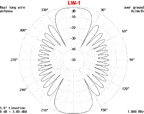
Figure 2 is the vertical pattern and it clearly shows a lot of minor lobes starting from 150 degrees to 30 degrees. These minor lobes should allow some communications close in, as they all seem to have significant strength for this.
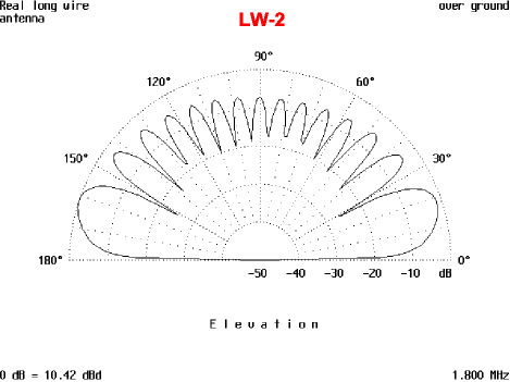
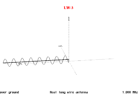
Figure 3 is the diagram of the current distribution along the antenna and it shows a fairly even distribution of current along the antenna. As you can see, this antenna would be very good on 160 meters, even though it is rather bi-directional.
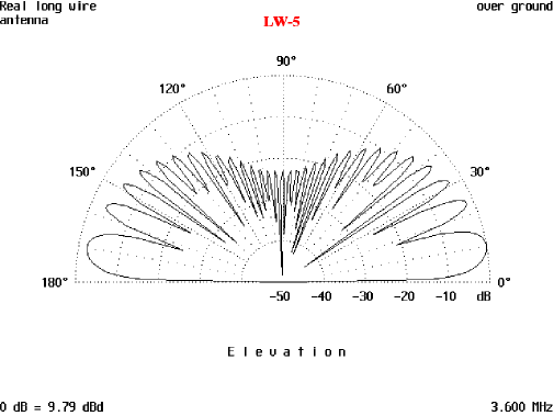
So, the next step was to see how the antenna would do on the higher bands. Shifting up to 3.8 MHz, we end up with a forward gain of 7.06 dBd, a front to back ratio of 2.00 dB and a beam width of 24 degrees. The radiation peak comes at 10 degrees and there is a gain of 9.79 dBd at the peak. This antenna would be fine on 75 meters. Figure 4 is the horizontal pattern and you can see there are a lot of very small spike-like minor lobes that should give some coverage to the sides.
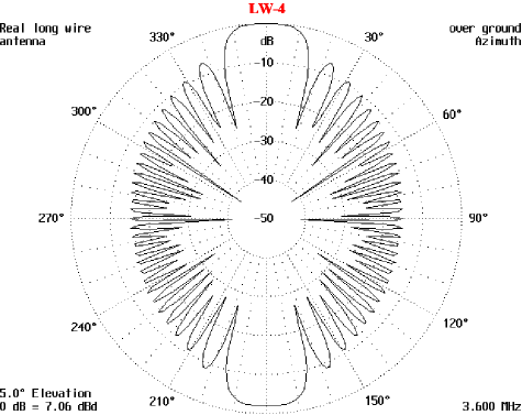
Figure 5 is the vertical pattern and it indicates there are a lot of very minor lobes in the vertical plane. These will allow some communications at medium to long range in conjunction with the two major lobes and along the axis of the antenna. Short-range communications do not appear to be as well as a dipole or inverted V would provide.
The last band that was modeled is the 40-meter band. The higher bands did not do well on this antenna, due to the very bad multi-lobing and increased angle of radiation taking place as the frequency was increased. So, 40-meters was the highest band modeled. 30 meters will possibly work well with this antenna, but was not modeled.
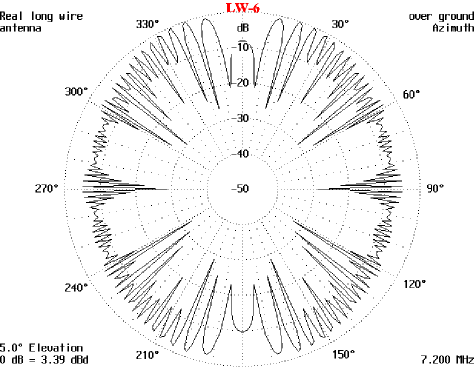
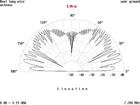
The horizontal pattern in Figure 6 shows no definite major lobes and maximum gain was at 19° and the reciprocals of this angle. The vertical radiation in Figure 7 also shows there is a radiation peak at 50° of 4.19 dBd, but it is a very narrow spike. From these patterns, it is becoming apparent there is a upper frequency limit to the size of a long-wire antenna and height above ground. This is due to the many lobes and ground reflections that limit the effectiveness of the antenna as frequency increases.
For most of us, an antenna 8 wavelengths long and ¼ wavelength above ground on 160 meters is totally out of the question. We have to make do with what will fit on our lots and not upset the neighbors. But it is fun to speculate on what a really big long-wire antenna would be like to use.
Originally posted on the AntennaX Online Magazine by Richard Morrow, K5CNF
Last Updated : 14th March 2024
